1955 – 1956 Dodge and Plymouth Fuel Tank Cleaning and 3/8″ Line Modification
(also applicable to Chrysler and DeSoto)
Introduction
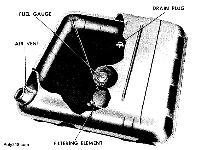
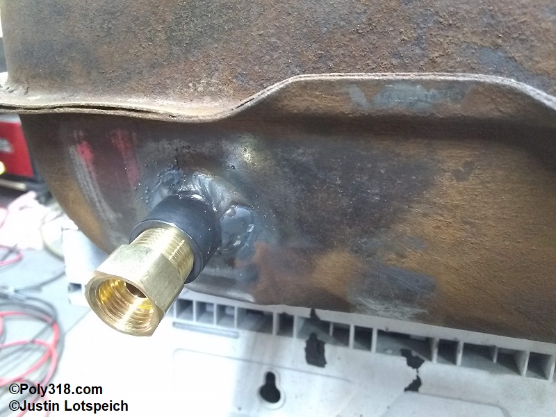
Factory 1955 – 1956 Mopars used a 5/16″ tube pickup with an oil-filter style screen located in the tank. The fuel pump sucks the fuel through the screen where it exits the front left (driver) side of the tank (Figure 1). The 5/16″ fuel line then runs down the left (driver) outside of the frame rail, crosses over to the right side at the front crossmember, and enters the mechanical fuel pump. For a factory engine under 300 HP with a 25 gallon-per-hour (GPH) mechanical fuel pump, this configuration works just fine; however, high-performance engines–especially those turning higher rpm and used on the track–require higher volume. The accepted calculation for Brake Specific Fuel Consumption (BSFC) theory on naturally aspirated four-stroke engines is 0.5 pounds of pure gasoline per 1 horsepower at wide-open throttle, which when converting weight to gallons comes out to 1 GPH per 12 horsepower. The gallons required increases the more alcohol is added to the mixture. While a stock poly 318 at 230 HP only needs 19 GPH of gasoline at wide-open throttle–well within the oem pump’s 25 GPH flow–a 456 HP engine needs 37 GPH and a 504 HP engine 42 GPH. For these engines, the factory pump would not keep up with the fuel demand, and the ability for the pump to move the fuel becomes harder with acceleration forces and resistance in the line factored in.
Replacing the factory 25 GPH pump with an aftermarket 80 GPH or 110 GPH pump may solve the volume requirement of the engine, but feeding that high-volume pump with the factory 5/16″ fuel line and fittings can cause unintended problems from pressure (due to the resistance of the narrow tubing and fitting passages) to pump cavitation (due to the line restricting the pump from flowing enough volume from the tank). When increasing pump volume, a larger-diameter line from the tank to the pump keeps the pump fed and reduces strain on the pump since the larger diameter line and fittings reduce resistance; keep in mind that there comes a point when the line from the tank to the pump becomes too large where the pump cannot handle the weight of the fuel coming through the line, so I don’t mean to suggest that a larger line is always better. The less bends, fittings, and length of the line from the tank to the pump also decreases resistance and assists the pump.
Unfortunately for those of us with 1955 – 1956 Mopars, no one makes a replacement fuel tank with a 3/8″ pickup tube. The tank pickup presents a major issue since the fuel volume is restricted to the smallest diameter in the system, so regardless of how large the line is from the tank forward. the system will flow only what the 5/16″ tank pickup can flow. My 450 HP 1956 Dodge coupe’s 390 stroker A-block with dual cross-ram AFB carburetors that is going to see track time requires a high-volume pump with a 3/8″ system, so I wrote this article detailing how I designed and built the system. While many of the components are rooted in performance, the article is applicable to those wanting to refurbish their factor 5/16″ system.
Fuel Tank Preparation
I hope it goes without saying that gasoline and any varnish in the bottom of the tank are highly flammable and when confined to the tank can be explosive. After pulling the tank, I drained the gas and a lot of flaked varnish into a container. I propped the tank up on its side with the filler neck facing down and left the tank in direct sun for an entire day to allow the fumes to evaporate. The next day, I plugged the fuel outlet fitting, filled the tank with one gallon of Pine-Sol–my go-to de-greaser parts cleaner–and a gallon of hot water, and worked the tank back and forth to agitate any varnish. I left the tank flat for two days to allow the Pine-Sol time to work on the varnish. I used a pressure washer attached to my water heater and cleaned out the tank. Between the Pine-Sol soaking and hot-water pressure wash, I got out all the varnish and found no rust damage inside the tank. I blew the tank dry with compressed air. In the past, for especially stubborn varnish, I’ve put pea gravel into the tank as an abrasive along with the Pine-Sol solution to break loose any varnish, but I didn’t need to use gravel for this tank. The Pine-Sol and hot water removed all remaining flammable residues, so I was ready to begin cutting and welding on the tank.
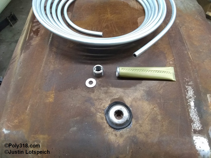
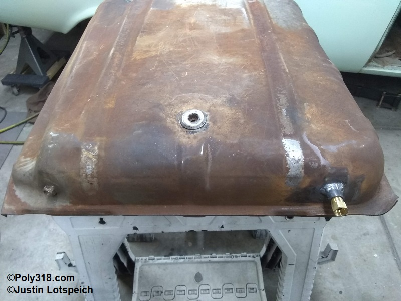
Since I couldn’t remove the 5/16″ pickup since the screen is larger than the sending unit hole, I planned on leaving the pickup intact and plugging the outlet with a 1/2″-20 inverted flare plug. I planned to install the new 3/8″ pickup on the right (passenger) side of the tank and run the line down the right frame rail since the pump is on the right side. This route will remove about 4′ of line compared to the factory routing. I spent time online piecing together parts and ended up getting a 3/8″ NPT bung and a 3/8″ inlet fuel pickup sock OER-K405 for a 1962 – 1981 GM from Jegs. I already had the 3/8 steel line and a 5/16″ washer (Figure 2).
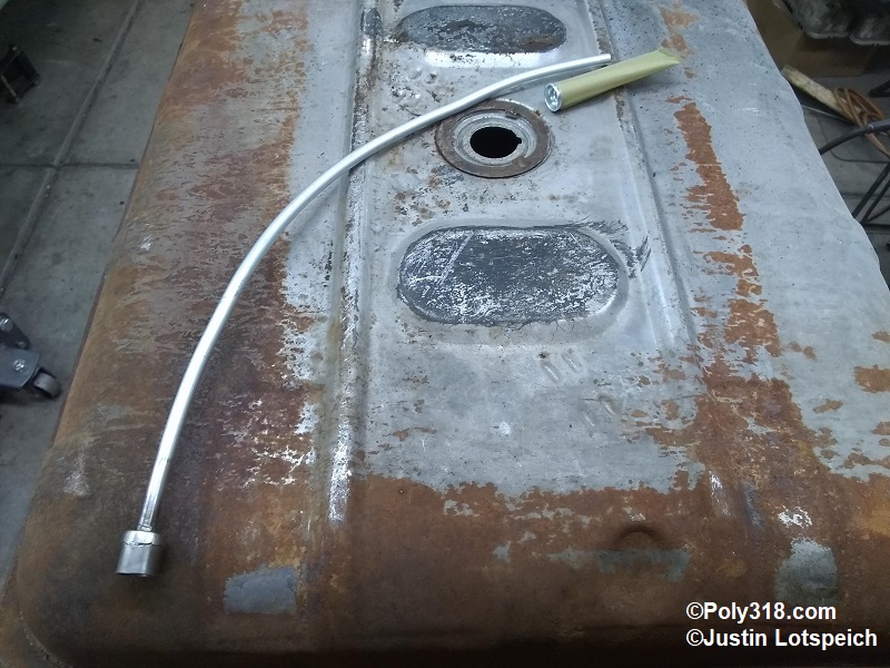
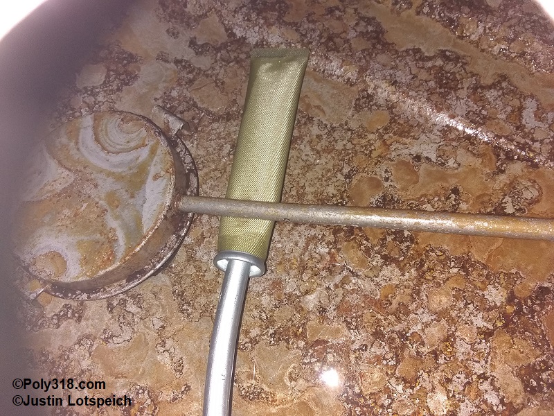
I sanded the front right of the tank wall to bare metal and drilled a 1/2″ hole. Working with a tubing bender and my knee, I put a sweeping bend into the new 3/8″ line until I got the inlet placed where I wanted it in the tank. The 3/8″ line fit under the original 5/16″ line in the tank, but I knew the filter sock wouldn’t clear. I inserted a carpenter’s “cat’s paw” through the sending unit hole, caught the underside of the factory 5/16″ line, and pulled it up to create a larger gap between the line and floor of the tank. My goal is to pin the new 3/8″ line with the old 5/16″ line to keep it from bouncing around and fatiguing where it welds to the tank.
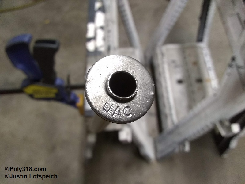
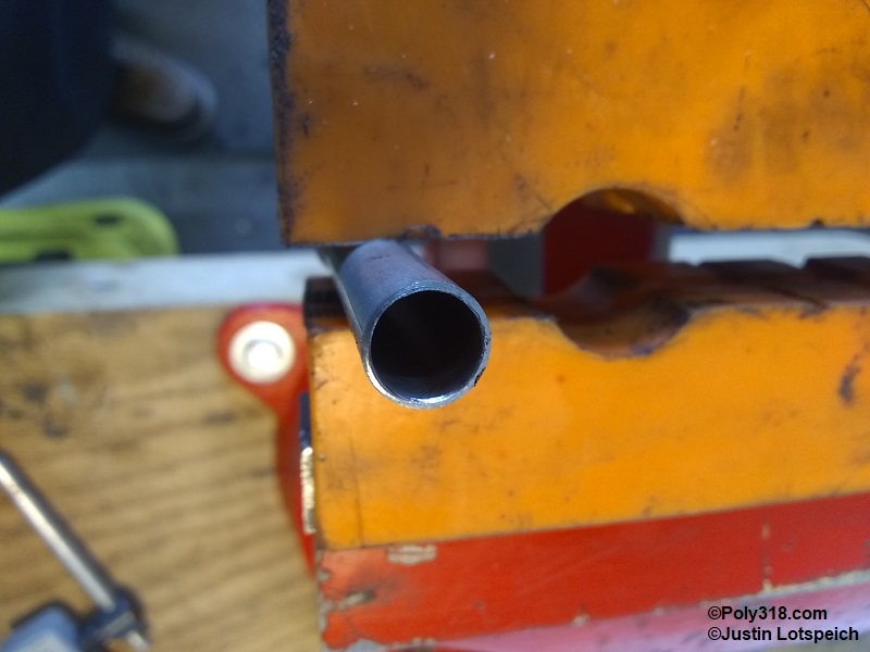
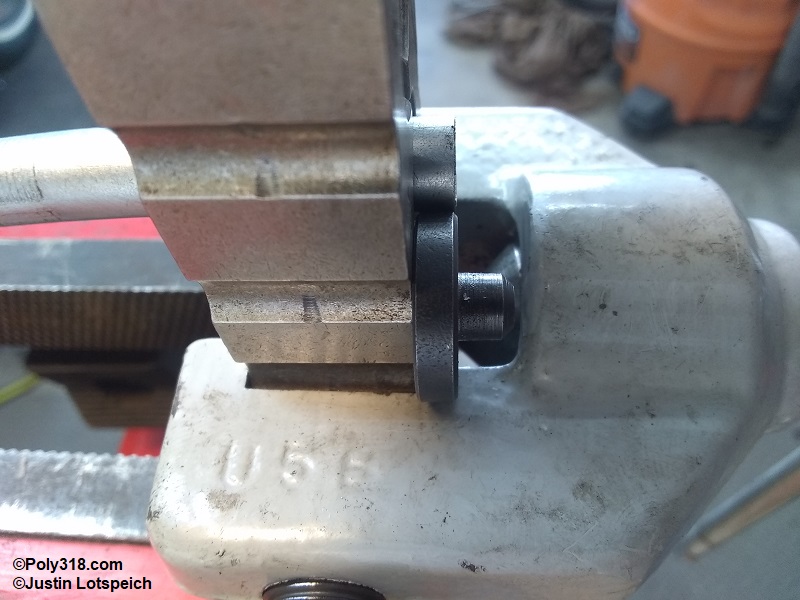
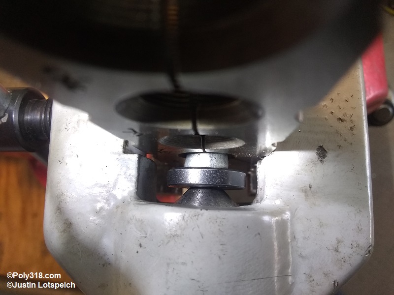
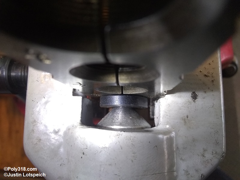
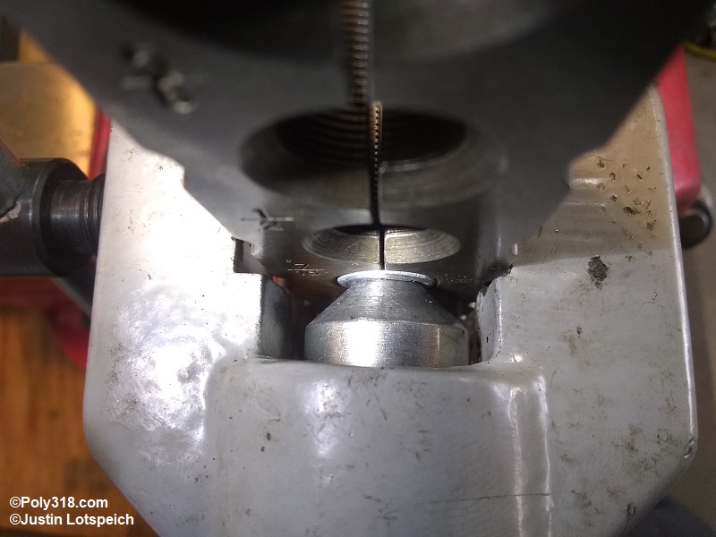
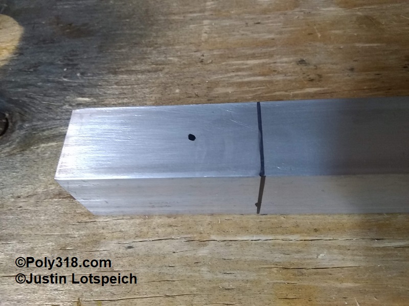
I used a bench wire wheel to clean off the zinc plating from the outlet end of the 3/8″ tube and the 5/16″ washer. At the outlet side of the 3/8″ tube, I secured the 5/16″ washer by pinching it against the 3/8 tube in a bench vice (Figure 3). This washer will act as a collar both against the tank wall and the 3/8″ NPT bung. While a TIG would be the best tool for this type of fine work, I don’t own one. I used my 130A MIG with argon to weld the backside (tank side) of the washer to the 3/8″ tube and used a hand file to clean up the weld where the washer sat flush against the tank wall when installed. I clamped the 3/8″ NPT bung against the washer in a vice, welded around the bung, and ground the weld smooth (Figure 4).
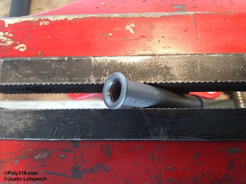
After sliding the 3/8″ tube into the tank, I positioned the inlet of the tube up through the sending unit hole. I slipped the filter sock onto the end of the tube and used a small machinist’s vice to very slightly pinch the end of the tube to where it belled out enough to where the sock could not slip off even though it was already crimped on nicely. I slid the 3/8″ tube and sock under the factory 5/16″ line and then took it back out to adjust the sock filter where it lay flat against the floor. Once I had the 3/8″ tube and sock positioned properly, I tack-welded the bung to the tank wall, triple-checked the positioning, and finish welded around the bung ensuring I didn’t have any gaps where it would leak (Figure 5). After the material cooled, I took the cat’s paw and gently pressed the factory 5/16″ line down onto the new 3/8″ tube/sock to firmly pinch them against the floor (Figure 6). When I bent up the 3/8″ line, I planned on this step and was sure to bend the last 5″ of the inlet parallel with the floor of the tank to where the very tip of the line would not pinch and cut through the sock filter. Figure 7 shows the front of the tank finished with an adapter to go from 3/8″ MPT to female 5/8″-18 inverted flare. From this point, the 3/8″ line with a male nut attaches and runs to the mechanical pump.
3/8″ Feed Line, Pump Connection, Distribution Block, and Carburetor Branches
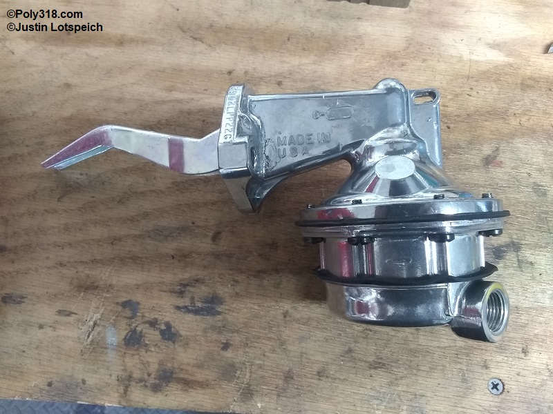
In order to utilize the 3/8″ tank outlet, the entire system must remain at least 3/8″ up to the pump. Running 3/8″ line from the tank to the fuel pump is not a problem, but the fuel pump is the limiting factory. The only manufacturer I know of who makes a fuel pump with a 3/8″ NPT inlet and outlet is Edelbrock model 1720 (Figure 8a). While an expensive unit ($210 at the time of writing this article), the pump has great benefits including a 110 gallon per hour flow rate, internal 6 psi regulator, adjustable outlet/inlet clocking, rebuildable, and made in the USA. The two Carter AFB carburetors are sensitive to fuel pressure where the needles can float with pressures over 6.5 psi, so the 6 psi cap will work well. With the Edelbrock 1720, my system will be 3/8″ from the tank pickup to the carburetor distribution block where 5/16″ lines will run to each carburetor.
Creating 45 Degree Double Inverted Flares
Before getting into fabricating the system and lines, I want to explain how I create double inverted flares. The tool I use is a Rigid model 345, which does a great job clamping the line without decreasing its diameter and producing flares. To create a double-inverted flare, I first ream the inside of the line to remove the lip from the cutting wheel (Figure 8b). I slide the line through the clamping tool allowing the line to stick out of the beveled side of the tool about 1/4″ and slide the flaring tool over the clamp from the hinged side. I then secure the clamping tool in a bench vice down at the hinged side. Holding the die backwards up against the clamp, twist/slide the line in or out until it is flush with the die (Figure 8c). Insert the die into the line, bring the flaring tool up to the die, and turn the tool until the flaring cone just touches the die without pushing the line in to center the tool. Tighten the side screw of the tool very tight against the clamp to compress the line. I place a drop of oil onto the tip of the flaring cone and die, which helps keep the cone from galling. Tighten the cone to fold the line until the die seats firmly against the clamp (Figures 8d – 8e). Back off the cone enough to remove the die, and run the cone in tight against the line to produce the inverted flare (Figure 8f). After removing the flaring tool and line from the clamp, I use a wire brush to clean off the flare and line where it rode in the clamp and inspect the flare for proper form (Figure 8g). After both ends are flared and brushed off, I blow compressed air through the line to clean out any debris.
Fabricating the Main Feed Line
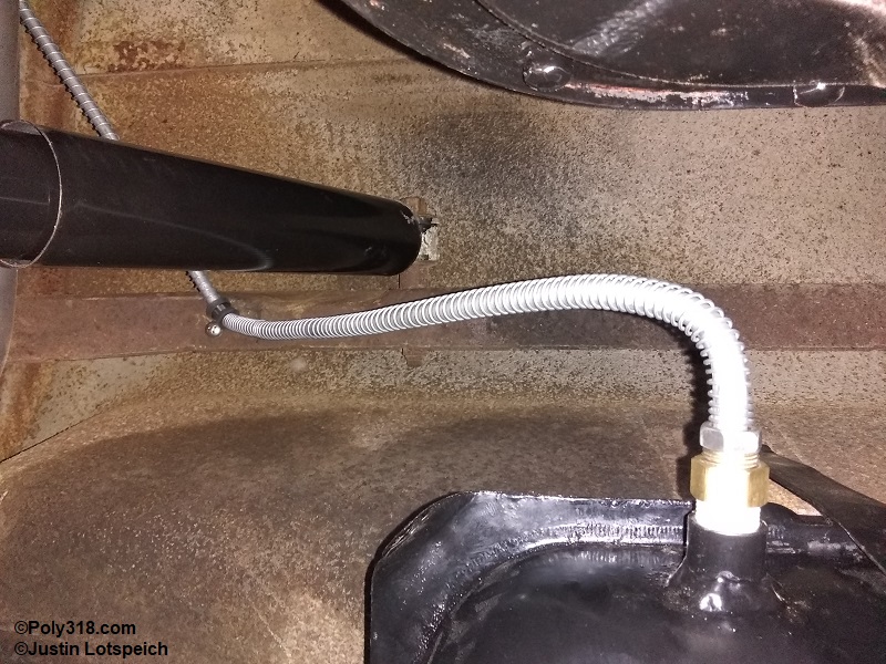
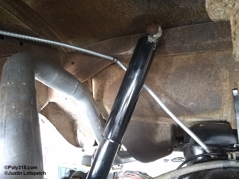
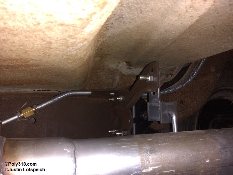
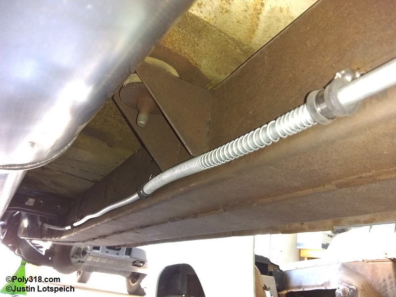
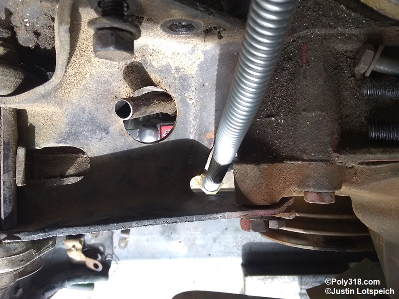
I started designing the system at the tank and decided I would need one joint in the main line in order to fabricate, install, and remove the line with the body mounted. I bent up the rear half of the line from the tank bung, up over the rear end, down the chassis kick-up, and brought it over the frame rail at the front leaf-spring perch to the inside of the frame rail (Figures 9a – 9c). I ensured plenty of clearance between the rear axle housing, right shock absorber, exhaust, and leaf spring. I installed a 5/8″-18 male flare nut and flared one end, installed stainless steel coil gravel guard due to all the possible rub points and potential damage, and installed another nut and flared the other end. I marked the location of the Adel clamps I used to secure the line to the chassis, drilled and tapped these locations for a 1/4″ bolt, and installed the clamps.
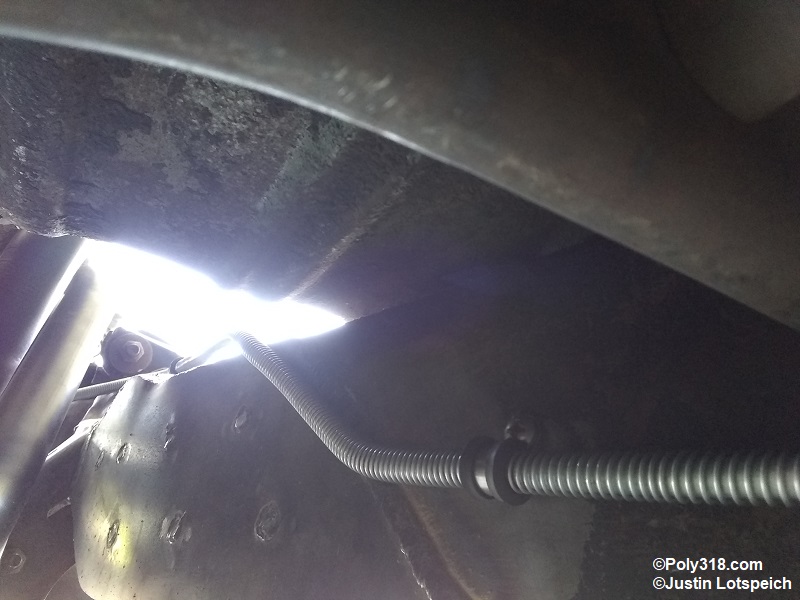
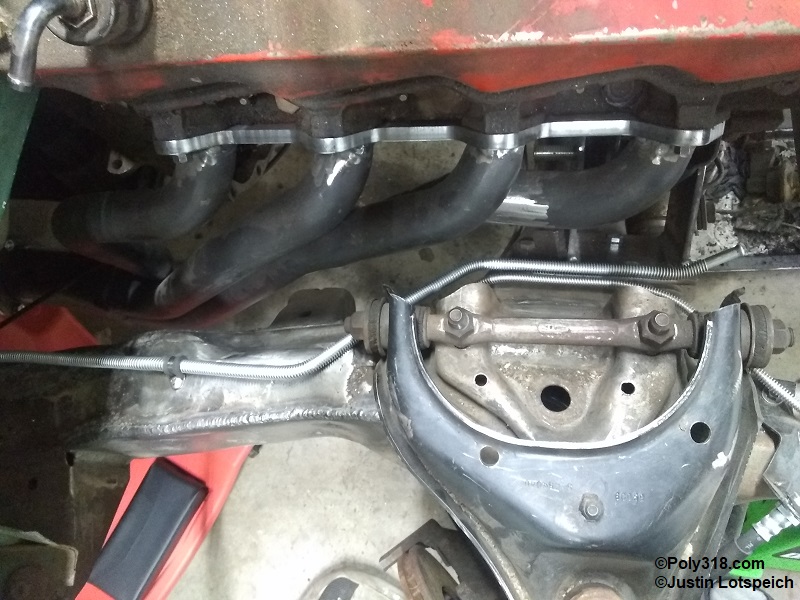
I came off the rear half of the main feed line with a 5/8″-18 double inverted flare coupler and bent the front half of the line to route under the middle body mounting bracket and transmission crossmember with plenty of clearance to allow easy removal of the crossmember. Forward of the transmission crossmember, I brought the line up and over onto the inside top of the frame rail just forward the firewall and carried it around the control arm and engine crossmember (Figures 9d – 9g). This route is 24″ shorter than the factory route, which helps decrease restriction since the pump has 24″ less to fight. I installed gravel guard at the body mount bracket and about a foot behind the transmission crossmember up to the fuel pump connection. The back end of the line received a 5/8″-18 nut, and the front received a bubble flare, which I made by partially collapsing the tubing in the first step of flaring that I cover above (Figure 8c) but stopping before the line was completely collapsed against the clamp. This connection will be the only soft connection in the entire system with 5″ of rubber fuel hose, which is necessary since the engine rises and falls with acceleration and will work harden a hard line to the point of cracking. The less rubber hose in the system the safer, and my local NHRA track technicians strictly enforce the rule that the entire fuel system can have a combined maximum of 12″ of rubber hose. The fuel pump inlet gets a 3/8″ NPT to 3/8″ hose barb 90° fitting. I placed Adel clamps at the back joint, forward the body mount, at 18″ intervals for the long straight section, and then where needed to secure the line at the front clip. I’m wary that the 90° pump inlet fittings will be too restrictive and cause fuel pressure drop at wide open throttle at the end of the 1/4 mile, so I may use a straight inverted flare adapter in the pump inlet port and bend up a long-sweep turn from 3/8″ line with a bubble flare to accept the hose.
Fuel Filter and Carburetor Distribution Block
As with many things in the automotive and hot rod world, there are rules of physics to follow and those to bend, and many times people don’t know the rule to begin with. The case in point is that for mechanical diaphragm fuel pumps, the last fuel filter before the carburetor(s) should be 30 – 40 microns and must be placed on the pressure side of the pump, as in between the pump and carburetor(s). I’ve purchased and worked on many a classic car/truck where someone placed an in-line 40 micron fuel filter on the suction side just before the pump, at the tank outlet, or both. Placing a 40-micron filter on the suction side is a no-no because it places undue resistance and thus strain on the pump since it has to fight to overcome the filter resistance to draw the fuel through the feed line. Depending on the engine’s fuel requirements, it may be oaky to place a 100 micron or larger filter or screen in the tank pickup or outlet to catch larger debris.
Connecting the filter to a hard line from the pump to the carburetor(s) is a common predicament because, unless the system uses -AN hose/fittings, it almost always requires using a barb/barb replaceable filter such as a Wix 33033. There’s noting wrong with cutting the hard line and creating a bubble flare, placing the filter with two short pieces of 3/8″ hose on each side, and then continuing another piece of hard line to the carburetor(s), but it isn’t aesthetically pleasing to me, and these types of replaceable filters are far more restrictive than other options such as cleanable metal mesh filters. A reader might think, “Why not just use a replaceable filter that has double inverted flare ends?” That’s a great idea, but in all my hours of searching over decades, I’ve never found one for 5/16″ or 3/8″ systems. There are wimpy filters that have 1/8″ NPT inlet/outlet that will accept a flare adapters like factory glass-bowl filters, but they are extremely restrictive and will starve anything but low-performance, low-rpm engines at wide open throttle. There is also a 1980s onward GM filter that looks like it has 5/8″-18 female double inverted flares on each end, but the ends actually take the GM o-ring flare. It wouldn’t be hard to make these flares just for the filter, but a quality GM flaring tool is expensive at about $300 at the time of writing this article.
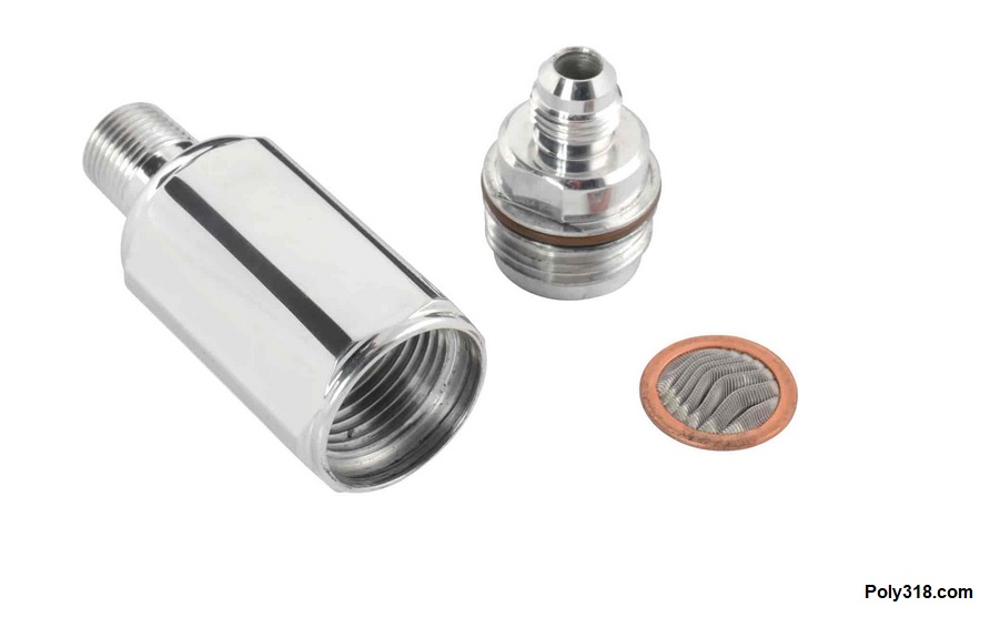
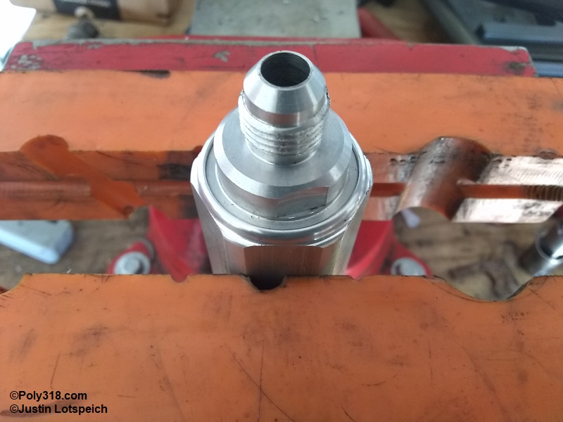
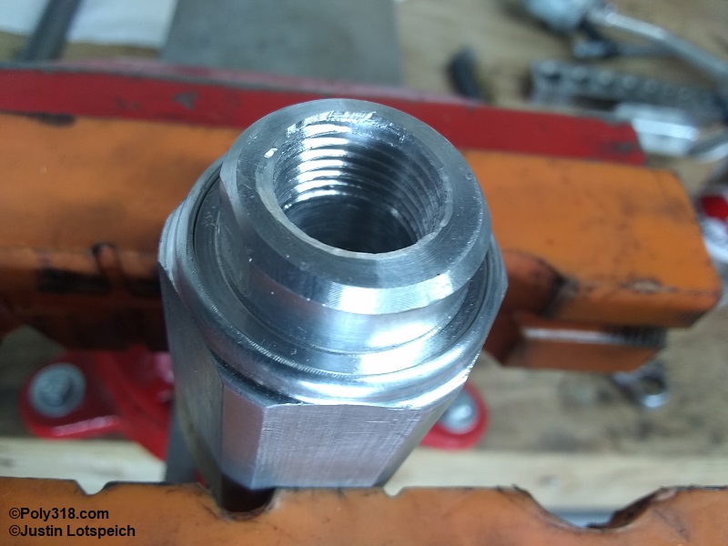
I like cleanable fuel filters due to less resistance and because I can reuse them, and I wanted to keep hard line from the pump to the carburetor distribution block. I dug through catalogs and websites until I found something with which I hoped I could work. I purchased a Jegs billet aluminum filter 555-15063 that has a 3/8″ male NPT end and a male -6 AN end (Figure 10a). Since I couldn’t find any photos of the inside of the AN end, I hoped that the aluminum was thick enough to be drilled out and tapped; when the filter arrived, I was happy that my premonition was accurate. I drilled out the AN side and tapped it 3/8″ NPT (Figures 10b – 9c). The male end threads into the distribution block, and the female end receives a flare adapter. Voila, I have a hard-line, cleanable, 3/8″ fuel filter.
For the distribution block, I cut, drilled, and tapped a piece of 1″ x 1.5″ aluminum billet including a mounting through-hole. The fitting configuration is 3/8″ NPT inlet, two 1/4″ NPT outlets for flare adapters that take the 5/16″ lines to the carburetors, and a 1/8″ NPT port for a fuel pressure gauge connection for diagnostics that will normally be plugged (Figures 10d – 10e).
Fuel Pump to Fuel Filter Line
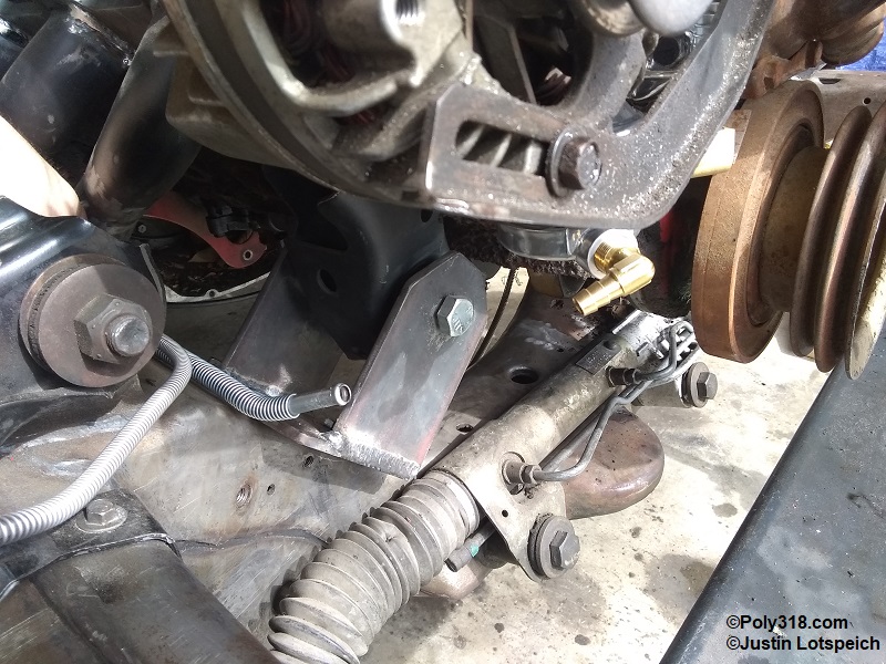
Ironically, the pressure line from the pump to the carburetor(s) is usually the shortest piece in the system yet the one that causes the most headaches due to tight room, multiple obstacles, and major heat sources. Many factory lines route from the pump up the front of the block and head just 1/2″ away from the hottest heat sources of the exhaust manifold and cylinder head. The hotter the fuel when it enters the carburetor, the less powerful the combustion and the more likely the engine will suffer vapor lock on hot days or when the vehicle is idling for prolonged amounts of time such as in traffic.
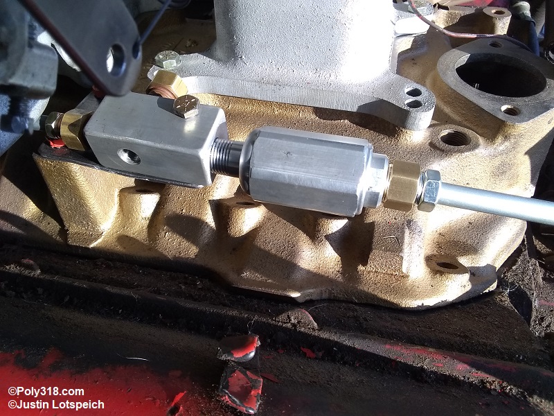
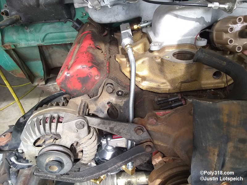
I played around with bending a scrap piece of the original 5/16″ line I tore out of the car to mock up two different configurations for this feed line. One option was to take the line up behind the alternator, jog it over in front of the valve cover, and turn it toward the fuel filter. The issue with this route was that after rotating the pump outlet into position, the inlet would face the oil pan to where I couldn’t make the connection to the main feed line. Unfortunately, the Edelbrock 1720 inlet and outlet ports cannot be rotated independent of each other. The next and better option for keeping the fuel line away from exhaust and cylinder-head heat and an aesthetically good choice was to come straight up from the pump, snake through the alternator bracket, and turn toward the fuel filter. While a restrictive fitting, I used a 90° 3/8″ NPT to 5/8″-18 female double inverted flare at the pump and 5/8″-18 nuts on each end of the line (Figures 11a – 11b). I’m less concerned about the 90° fitting in this section since it’s on the pressure side of the pump, but if the engine suffers from pressure drop at wide open throttle, this fitting will be one of the first things I change during diagnostics.
Carburetor Branch Lines
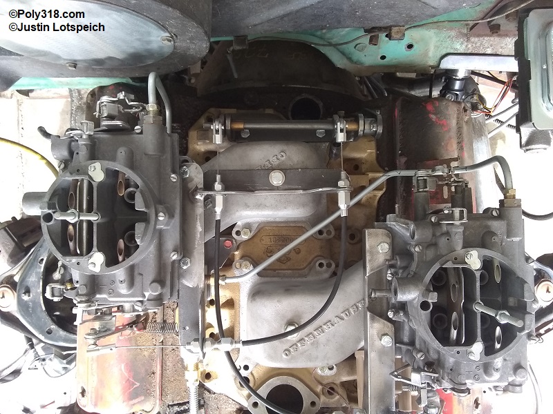
Coming off the distribution block, I fabricated a 5/16″ line underneath and up behind the right cross-ram adapter and carburetor with 1/2″-20 nuts on each end. I snaked the other 5/16″ line from the distribution block, through the cross-ram adapters, and up the back of the left carburetor. I kept both of these lines far off the intake manifold to reduce heat exposure. This line also received 1/2″-20 nuts on both ends (Figure 12).
Conclusion
While designing an improved fuel system for Forward Look cars takes a lot of time and the fabricating takes a lot of patience, exact measurements, and wire templates, it’s an achievable goal. In my experience as a very rough rule of thumb, for performance engines making 400 – 500 HP and that will see higher rpm at the track, going with a 3/8″ system with as little restriction as possible is necessary to keep the engine from starving under wide open throttle conditions. For most engines under 400 HP, especially for those under 300 HP and that won’t see over 4,500 rpm at wide open throttle, a 5/16″ system works fine as evident from all the 1950’s Mopars produced. I can only make the above statements in a very general manner since the entire vehicle from weight, rear wheel diameter, rear axle gearing, transmission gearing, torque converter specs, cam profile, carburetor(s), etc. must be factored in. Depending on these variables, an engine may require an electric fuel pump paired with a 5/16″ or 3/8″ system in order to overcome any resistance to provide the engine with enough volume, and other builds may require even larger line.
A main takeaway I hope to leave readers with is that the smallest diameter of the system–whether a hard line or fitting–dictates the volume the system can flow. Running 5/16″ line with a pump that has 1/8″ NPT threads means the system is only flowing the volume of a 1/4″ line. That configuration might be fine for a 230 HP engine that turns 4,000 RPM, but good luck maintaining fuel supply at wide open throttle on a 350 HP engine turning 6,000 RPM. At the opposite side of the system, I come across people at the track, cruise nights, and online with cars that came stock with 5/16″ lines who have put in larger or more powerful engines and changed the lines from the tank forward to 3/8″ or even -8 AN, yet they retained the factory 5/16″ sending unit/pickup. That’s a whole lot of money and time spent to retain a 5/16″ system since the pickup meters the system to 5/16″. When in doubt, spend time running calculations of Brake Specific Fuel Consumption in the context of the entire build, and driving the vehicle and monitoring the vitals will be the ultimate test.