Poly 318 Oil System Modifications
(applicable to poly 277, 301, 303, 313, 318, 326 and LA 273, 318, 340, 360)
Introduction
As part of my larger Poly 318 engine rebuilding series, there are some easy modifications using common shop tools that will improve the A-block oiling system over the factory’s design and finish work. This article can also be used by those with LA engines. The easier oil flows through the system at maximum volume and the quicker oil gets to necessary components and back to the pan the better, especially since the oil has multiple sharp angles to negotiate including the crank, cam, and lifter passages. Ensuring the timing set gets good lubrication is also crucial especially for high rpm performance applications. Converting a standard volume pump to a high-pressure pump (not high-volume) is also wise for performance builds.
The oil pump, rear main cap, block, and cylinder heads rely on drilled oil galleries and a series of drain-back holes cast and drilled into the components. For a stock engine, the design functions fine. For performance engines, the system benefits from modification. One issue is that the drilled gallery holes have ridges and 90° turns with sharp edges; the cast drain-back holes have rough flash that impedes oil flow; the front drilled drain-back holes in the lifter valley are placed too high above the valley floor where oil is more likely to accumulate before draining through the valley holes; and the factory spin-on filter adapter uses only four 1/4″ holes that limit volume and create turbulence in the chamber.
Another issue with the factory A-block system is that there is no pressurized oiling of the timing chain and sprockets. The system relies primarily on windage from the crank splashing oil onto the crank timing sprocket and carrying the oil up the chain to the cam sprocket, which is not a guarantee especially under hard acceleration where oil moves toward the rear of the pan. The design of the front block and cam thrust plate does not allow oil exiting the lifter valley drainback holes to contact the sprockets and chain. Mopar began addressing this issue in the LA in around 1968 by drilling the upper right (passenger) thrust plate mounting hole through to the lifter gallery and using a hollow bolt to spray oil onto the cam sprocket where it would fling out onto the chain. Later in the 1970s, they dropped the hollow bolt and began using a sheet metal tab that guided residual oil from the cam bearing to drip onto the crank sprocket. The system I have designed implements similar methods but is guaranteed to get plenty of oil onto the timing set and between the cam and thrust plate.
Converting and Blueprinting a High-pressure Oil Pump
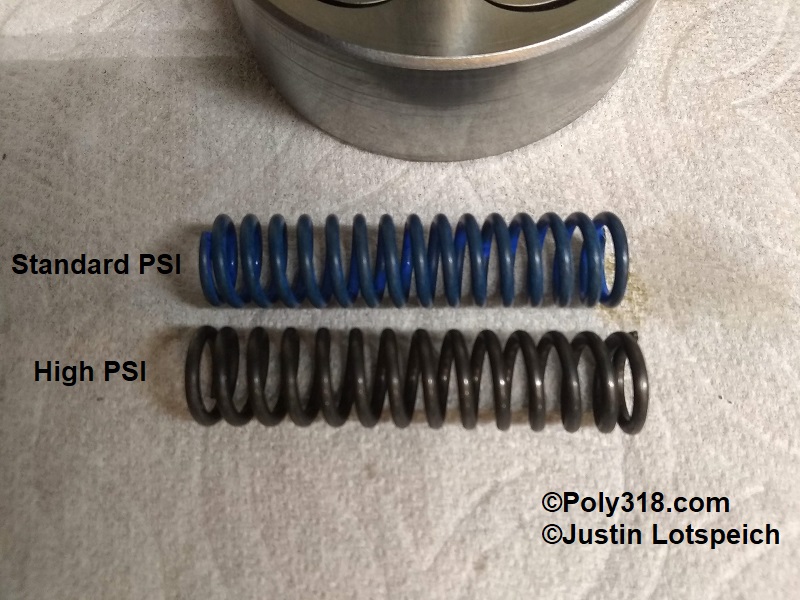
I do not use high-volume oil pumps for the reasons they draw more power to turn, are not necessary for even high-performance A-block engines, and the A-block cylinder head drainback holes are too small to adequately handle additional volume but cannot be drilled out due to lack of material in the block. Instead, I blueprint a standard Melling M72 pump and install the high-pressure spring Mopar used on the six-pack LA340s.
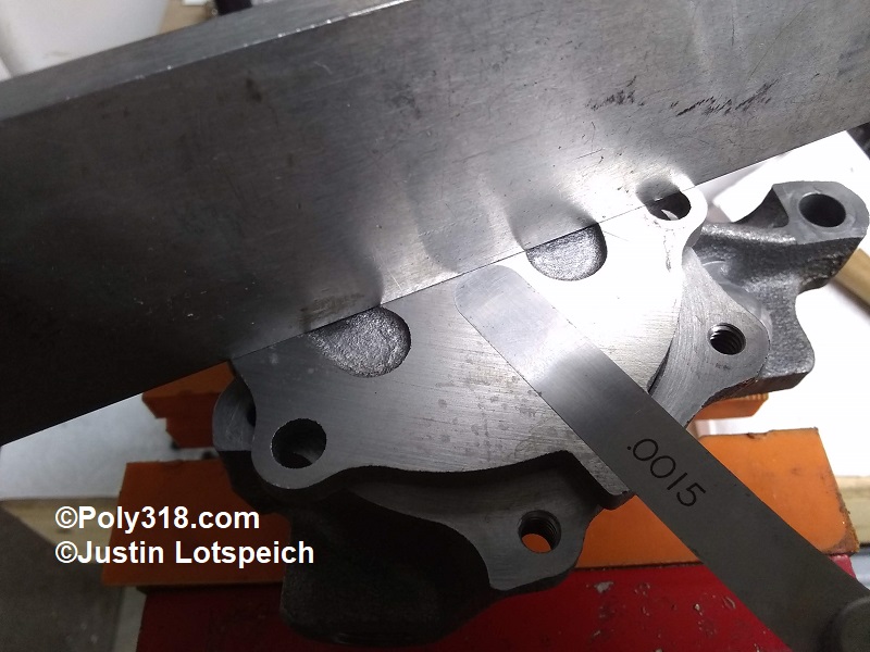
- With the pump secured in a vice with soft jaws, remove the five 1/4″ cover bolts. Flip the cover upside down, wipe off any oil, and place a machinist’s straightedge across the cover. Using a “go/no go” method, check the clearance with a feeler gauge in three spots across the straightedge (Figure 1). Rotate the straight edge in an “X” pattern and check across the straightedge. The gap should be no more than .0015″. If the gap exceeds .0015″, place 220 grit wet sandpaper on a flat surface such as glass and sand the cover in an “X” pattern to plane it flat within spec. In the case of my pump, I could not fit a .001″ gauge.
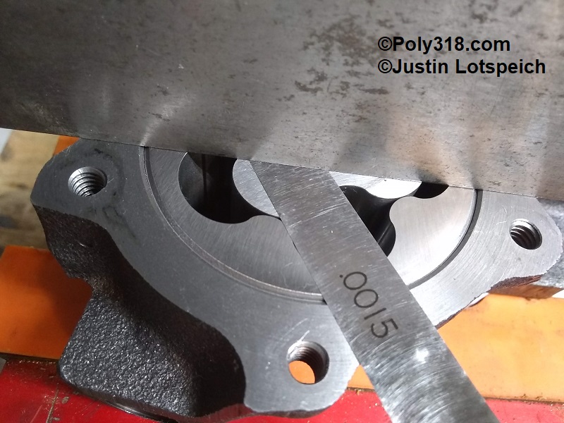
- Remove the inner and outer rotors and wipe off any oil from them and the housing. Reinstall the rotors. Place the machinist’s straightedge across the body, and use a “go/no go” method to check the clearance between the outer rotor and straightedge and the inner rotor and straightedge at the four points of an “X” pattern (Figure 2a and 2b). The clearance should be at least .001″ and no more than .004″. If the clearance is too tight, sand the rotor(s) on the wet sandpaper; if the clearance is too loose, obtain a different pump since the housing is likely machined too deep. My pump measured .002″ for the outer rotor and .0015″ for the inner rotor.
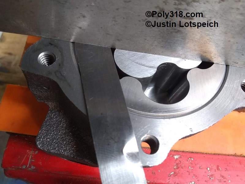
- Using one hand, pinch the inner rotor tight against the outer rotor to one side of the pump housing. Using a “go/no go” method, check the clearance between the inner and outer rotor teeth (Figure 3). The clearance should be between .001″ and .006″. If it is out of spec, obtain another pump. My pump measured .002″.
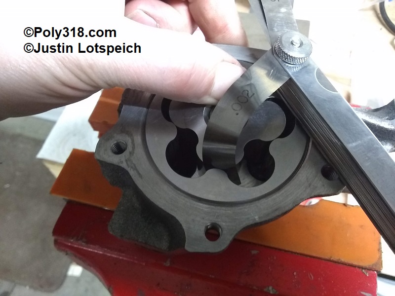
- Remove the inner rotor, and use a “go/no go” method to check the clearance between the outer rotor and the housing wall (Figure 4). The clearance should be between .002″ and .012. If it is out of spec, obtain another pump. My pump measured .008″.
- Lift out the outer rotor and set aside.
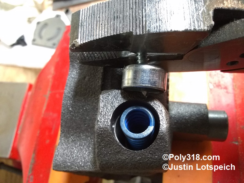
- Remove the pressure-relief spring cotter pin and drill a self-tapping sheet metal screw into the center of the spring retainer expansion plug. Use a pair of pliers to pry out the cup (Figure 5).
- Remove the pressure relief spring and piston and set aside noting the direction the piston installs.
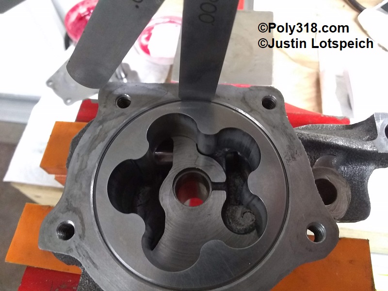
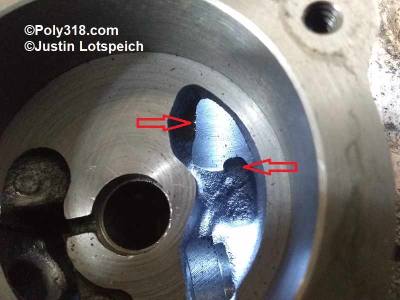
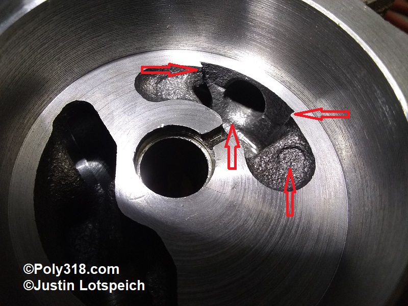
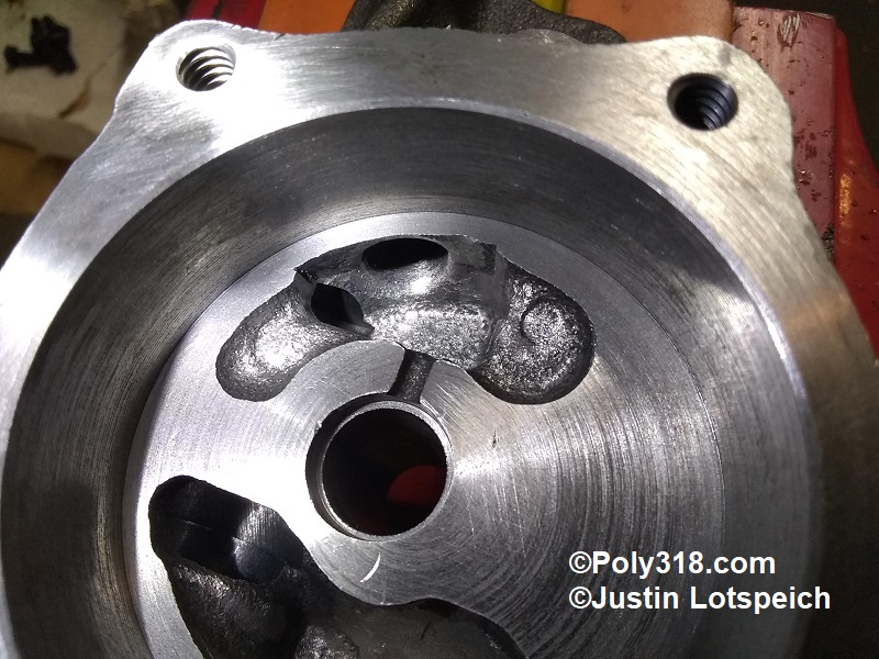
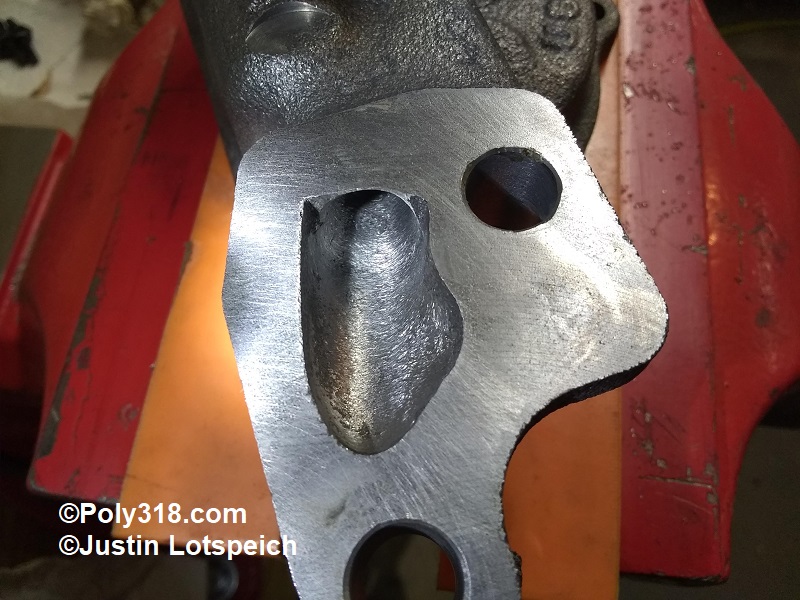
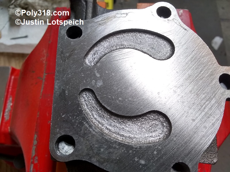
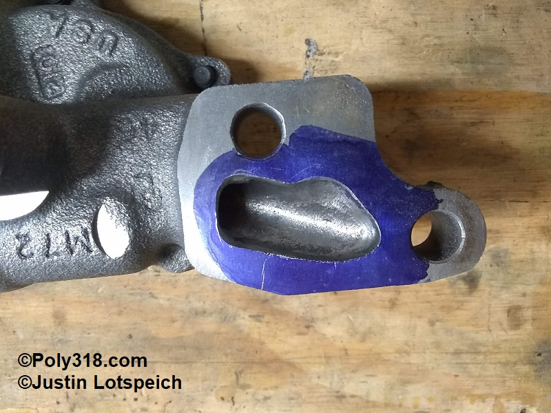
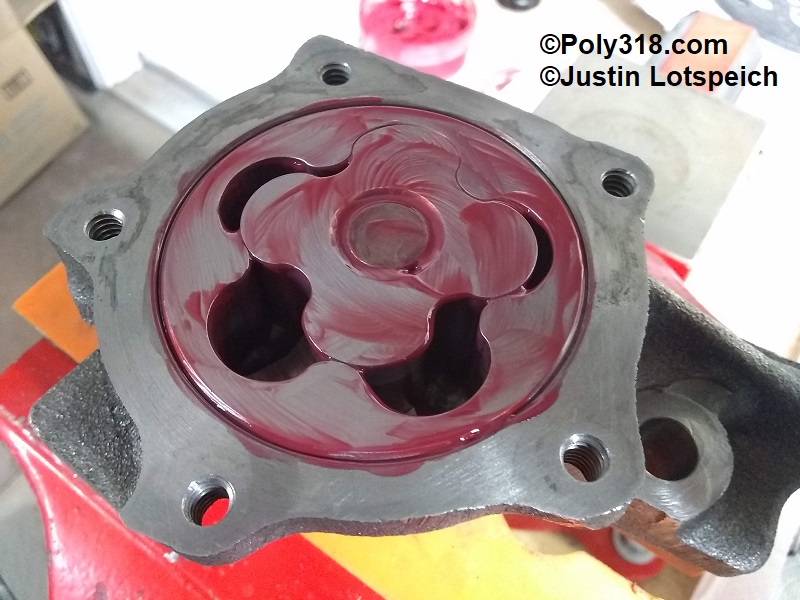
- Inside the housing wells, note the sharp ridges and rough casting surfaces at the pump inlet and the pump outlet (Figures 6 and 7). Flipping over the pump, notice the ridge and rough casting surface where the pump mates to the block main cap (Figure 8). Inspecting the underside of the housing cover, notice the rough casting in the wells (Figure 9).
- Use the ball and tapered point carbide bits to smooth out the ridges and rough casting being very careful not to hit the machined floor and wall where the rotors ride, the cover’s machined surface, and the mating surface of the pump and main cap (Figures 10, 11, 12, 13, 14). Note the thickness of the casting to gauge how much material you can remove. For example, the housing inlet chamber can be cleaned up a lot, but the outlet chamber is thinner-walled.
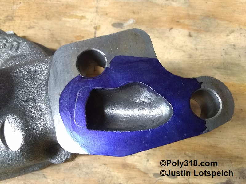
- After applying Dykem blue or similar, trace the pump gasket and port out to the line using the carbide bit, rounding the short turn of the inlet (Figures 15 and 16).
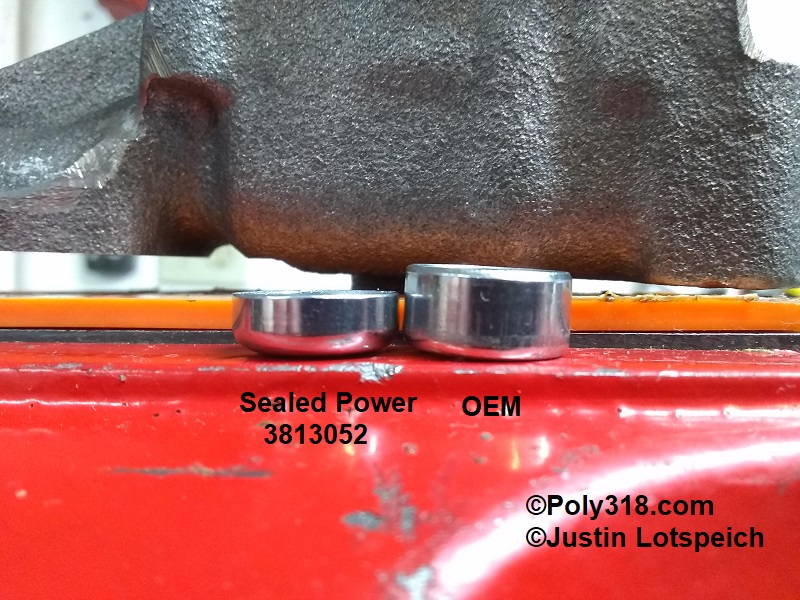
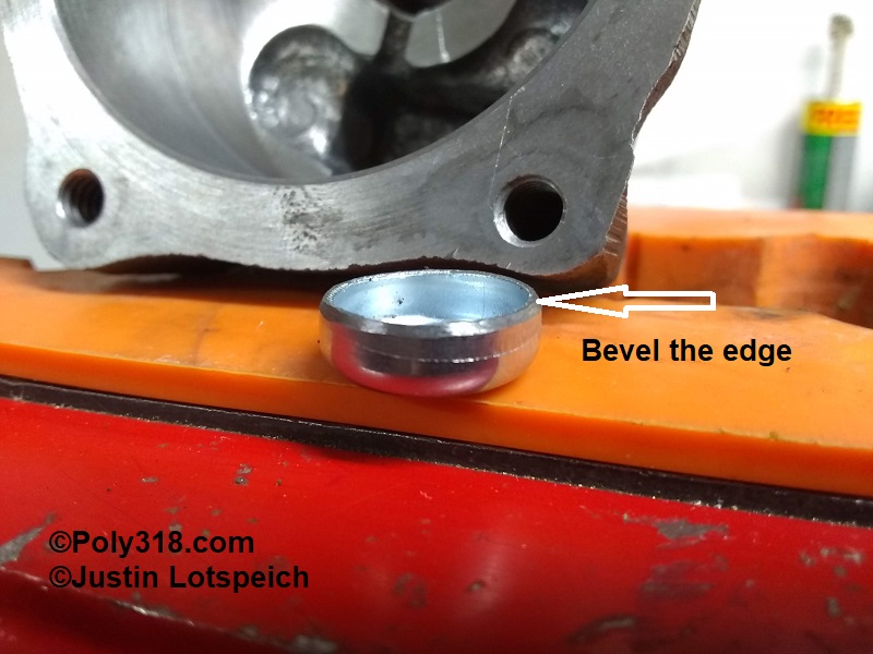
- Obtain a new 5/8″ deep steel expansion plug Sealed Power 3813052 or similar. Note that the Mopar Performance high-pressure spring kit P3690944 used to include a new plug but no longer does even if the online image shows a plug. The above 5/8 plug is not as deep as the OEM (Figure 17), which is not an issue, and it is slightly thicker gauge than the OEM plug. I miced the original plug and high-pressure spring assembly and the replacement plug and spring assembly and found that the replacement plug will compress the spring .005″ more than the OEM plug, thus increasing the pressure very slightly but likely unnoticeably. Using a bench grinder or file, bevel the open end of the expansion plug to ease installation (Figure 18).
- After all machining of components is completed, thoroughly blow off/out all the pump components with compressed air, clean in solvent, and blow them dry.
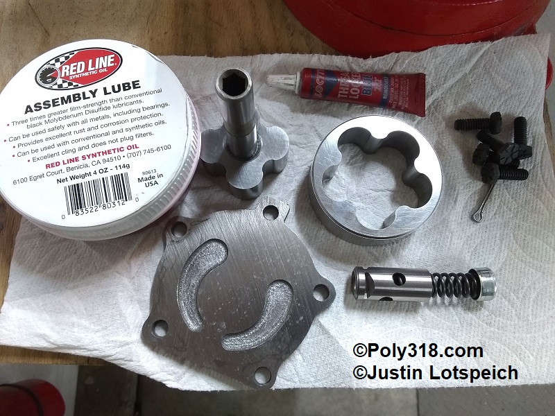
- Working in a clean area, secure the housing in the vice. Lubricate the pressure-relief piston with assembly lube (I use the same Red Line #R0613 I use for engine assembly) and install with the four slots going in first (Figure 19).
- Install the bare steel, slightly longer high-pressure spring from the Mopar Performance kit P3690944. The blue spring is a spare factory pressure spring (Figure 20).
- Lubricate the beveled edge of the expansion plug and insert it with the open end facing into the housing. Use a 7/16″ deep socket or drift to drive in the plug just until is passes the cotter-pin holes (Figure 21 and 22). Insert the cotter pin and bend over the end. Warning: Insert the expansion plug into the bore with the open cup facing into the housing. If installed with the cup facing out like a block coolant freeze plug, the spring will be compressed 1/4″ too much to where the pump will exceed the engine’s allowed oil pressure and produce around 110 psi.
- Liberally lubricate the rotor well’s floor and wall (Figure 23). Lubricate the outside and bottom of the outer rotor and drop it into the housing. Lubricate the inner rotor shaft, teeth, bottom where it rides on the housing floor, and drop it into place. Lubricate the top of both rotors keeping excessive lubricant off the cover sealing surface (Figure 24).
- Place the cover onto the housing, and install the bolts using a dab of blue Loctite. Torque the bolts to 120 in.-lbs.
- Insert a hex wrench into and rotate the inner rotor a few rotations to ensure the pump operates smoothly and to spread the lubricant throughout the unit. I write “HP” (high-pressure) on the cover and spray the outside with WD40 if I will not be installing the pump for some time to keep off rust and to remind me it is converted and ready to install. Bag the pump airtight until it will be installed during engine assembly.
Engine Block Oil Modifications
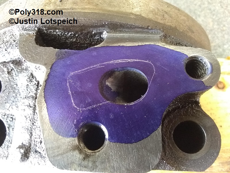
- Apply Dykem Blue or similar to the top of the rear main cap, and trace the oil-pump gasket (Figure 25).
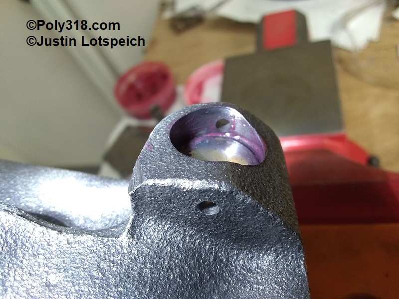
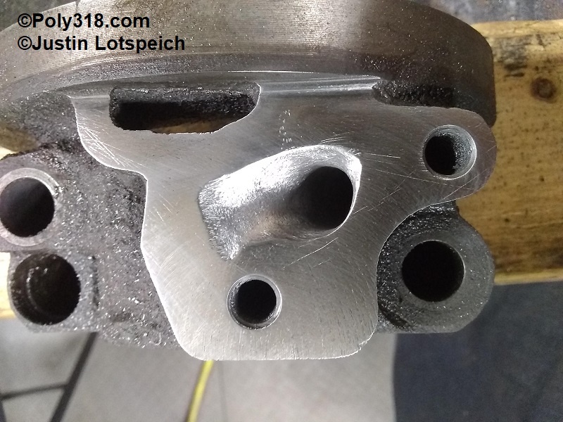
- Use the ball bit to carve out a sloped bowl radiused down into the hole (Figure 26).
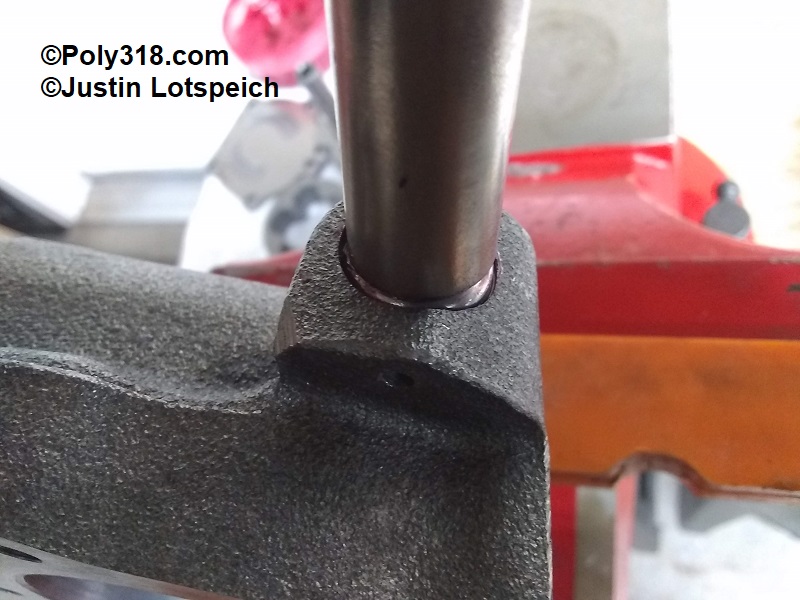
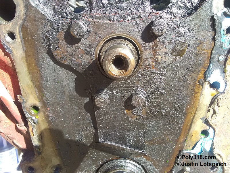
- Using the ball bit without spinning it, reach down the rear main cap passage and feel the walls for any offset between the cap and the block connection. Remove any offset moving the bit up and down (Figure 27).
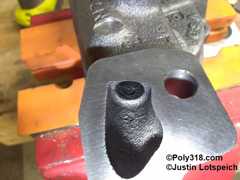
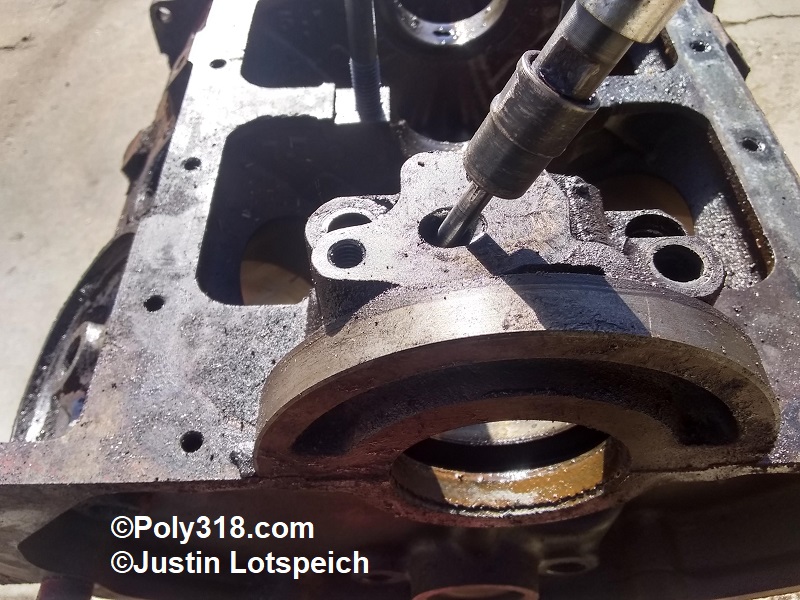
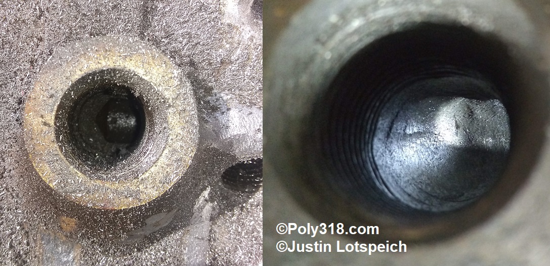
- After removing the rear main cap, reach the ball bit down the filter intake passage where the horizontal gallery intersects and round off the long-turn ridge. Catch and round off the sharp short turn with the back of the ball (Figure 28). Note: 1956 – approx. 1962 blocks may have a bypass valve instead of a blind hole or plug. If using a canister filter, this valve should be tested and replaced if necessary since they often deteriorate. If using a spin-on filter, the bypass valve needs to be removed and the passage plugged (see my oil bypass valve technical article for plugging information).
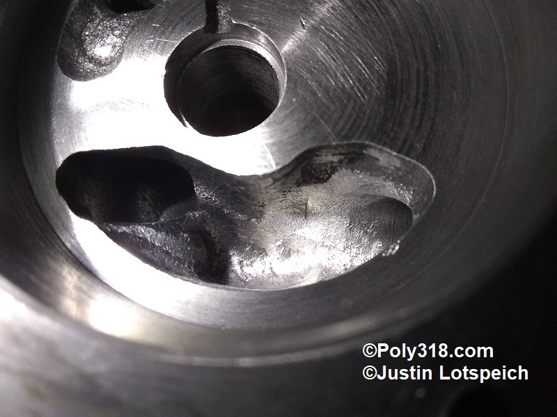
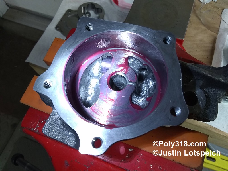
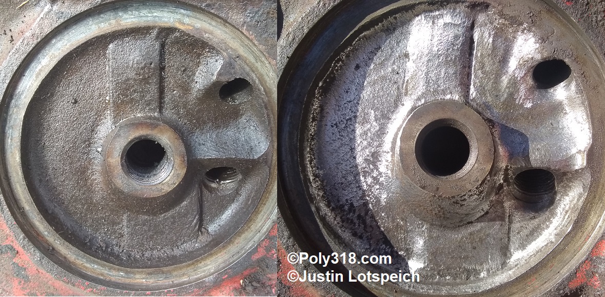
- Using the ball bit, chamfer the oil filter chamber intake hole and smooth out the chamber of all rough casting and ridges. In particular, the outlet gallery plug has a sharp cliff directly in the line of flow where the oil enters the chamber (Figure 29). Caution: be careful not to grind the adapter plate sealing surface or threads.
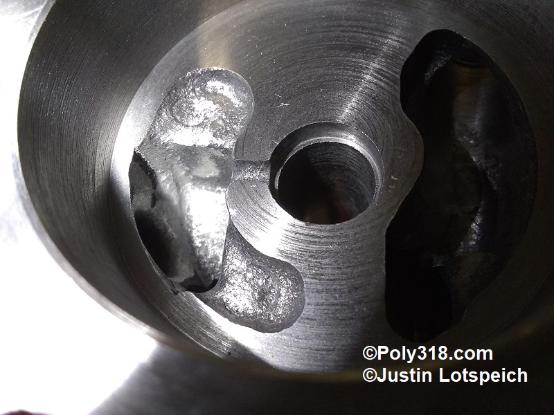
- Using the ball bit, reach into the filter outlet and round the sharp long turn. Catch and round off the sharp short turn with the back of the ball (Figure 30). Caution: be careful to not damage the threads.
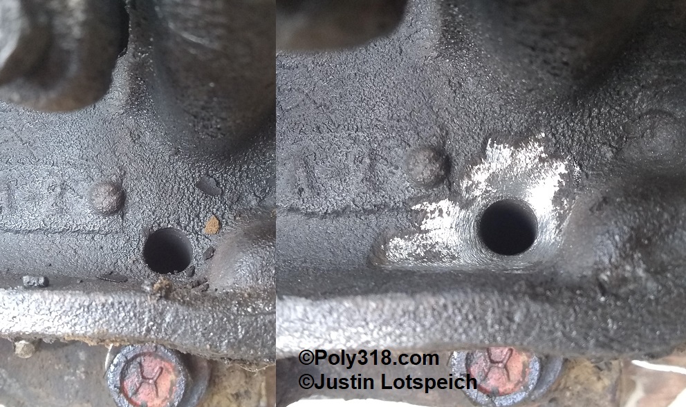
- Using the ball bit, reach into the plugged outlet gallery through the filter chamber and through the back of the block and round the sharp short turn (Figure 31). Caution: be careful to not damage the threads.
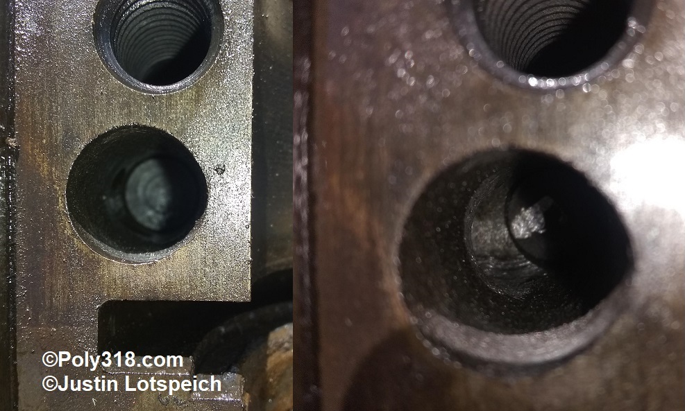
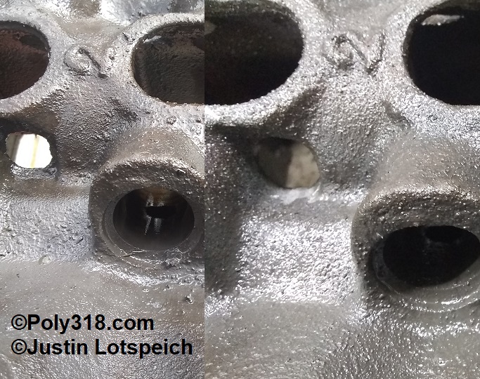
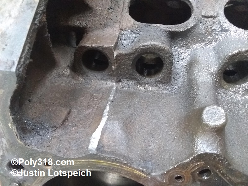
- Using the tapered bit, remove flash from and chamfer the oil drain-back holes in the lifter valley (Figure 32).
- Using the tapered bit, remove the vertical flash toward the rear of the valley that impedes flow (Figure 33).
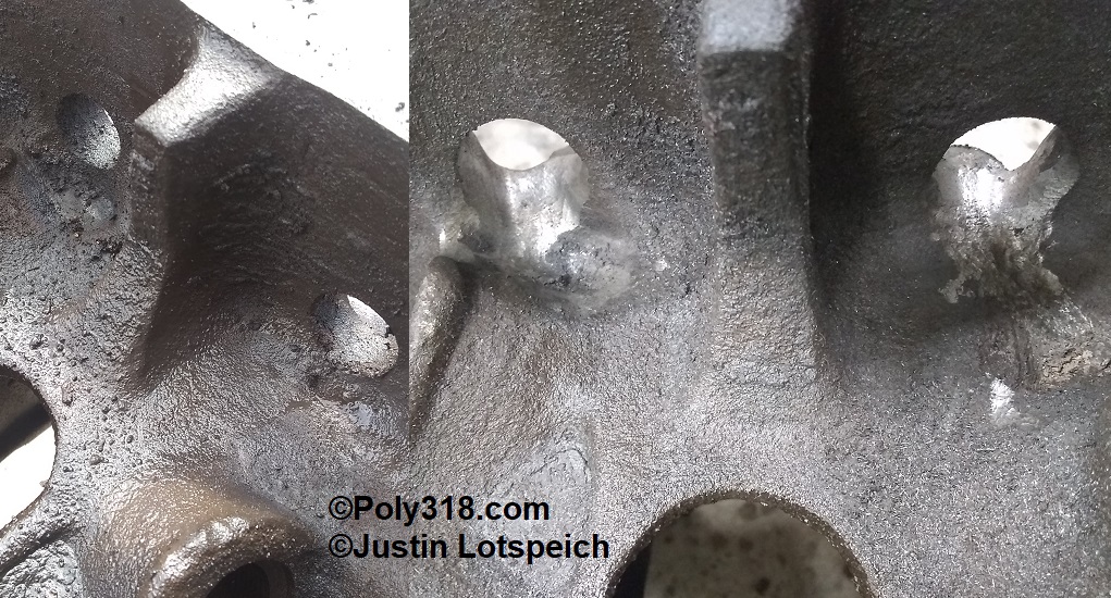
- Using the tapered bit, elongate and radius the front drain-back holes (Figures 34 and 35). Caution: be careful not to thin out the cam retainer thread bosses too much.
- Using the ball bit, chamfer the four oil drain-back holes in the cylinder heads (Figure 36).
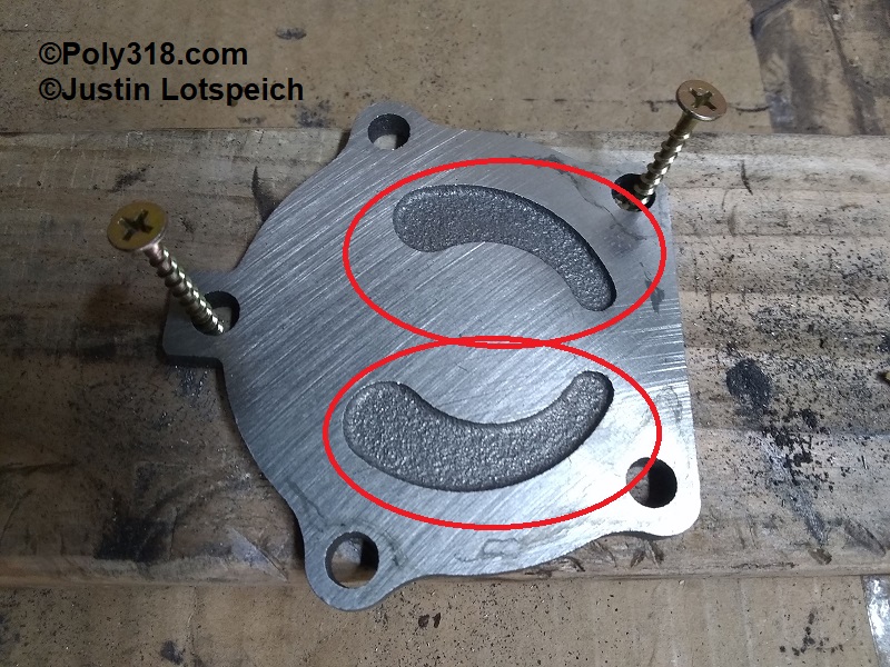
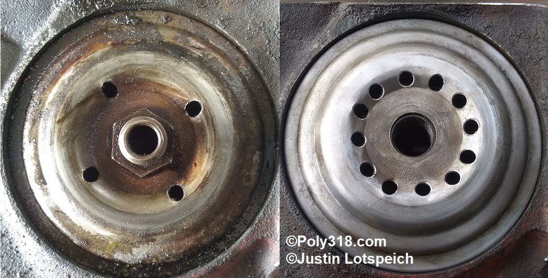
- Drill and chamfer an additional eight 1/4″ holes in the oil filter adapter plate (Figures 37).
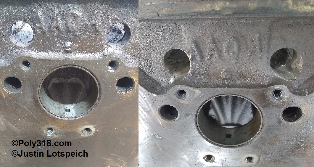
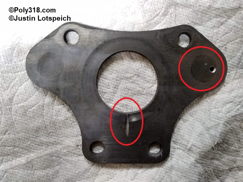
- Using the wear marks on the back of the camshaft thrust plate as guides, cut/file a shallow slot into the center bottom of the plate backside to direct oil exiting the camshaft bearing into the area between the cam and thrust plate (Figure 38).
- The thrust plate plugs the left and right lifter oil galleries, whereas most LA engines after 1966 use expansion plugs. Using the discoloration on the plate as a guide, drill a 1/16″ or #52 hole through the thrust plate on the outer portion of the right (passenger) lifter oil gallery discoloration and chamfer the gallery side of the hole with a 1/8″ bit (Figure 38). This hole is placed to where it will spray a steady stream of oil directly onto the chain and sprocket.
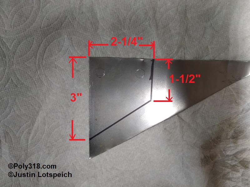
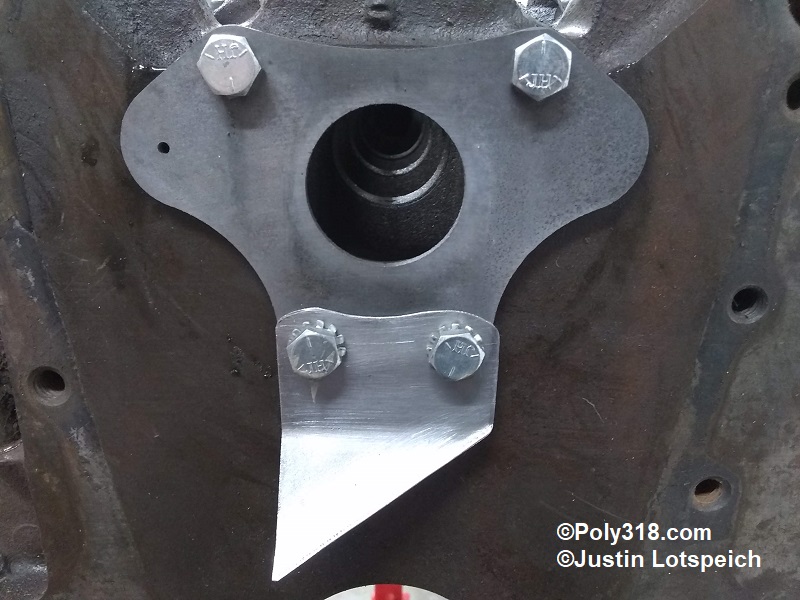
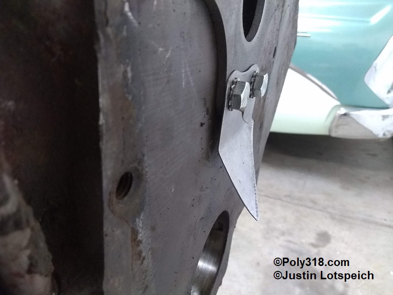
- Many 1956 – around 1961 A-blocks incorporated a timing set drip tab that was not used on later A-blocks (Figure 39). The drip tab is a good idea for performance builds since it directs a constant flow of oil onto the crank timing sprocket and chain. If I don’t have an early factory drip tab, I build one but place the drip point on the opposite side (right side of the engine) since the engine rotation will make better use of bringing the oil up the chain and onto the cam sprocket. Using the measurements in Figure 40 that I have confirmed clear the cam sprocket and place the oil drip in the correct location, mark a piece of 20 or 18 gauge sheet metal. Use the thrust plate as a template to mark the lower mounting holes. Drill the holes and cut out the tab. In a vice, break an approximate 35 degree lip outward on the very bottom diagonal edge of the tab to direct oil down the tab to the drip point. Break another approximate 35 degree horizontal across the tab at 1-1/2″ down from the top. Ease all the edges with a file to remove sharpness, especially at the drip point since it is fishing-hook sharp. When mocked up, the setup should look like Figures 41 and 42. After assembling the timing set, you will bend the tab toward or away from the block to fine-tune the drip above the the crank sprocket depending on if you use a single or double chain.
Figures