Poly 318 Oil Pump High Pressure Conversion and Blueprinting:
Melling M72
(also applies to LA 273, 318, 340, and 360 engines)
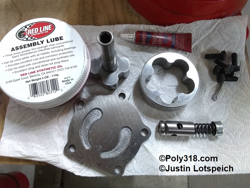
As part of my larger technical article on performance oiling system modification, converting the trustworthy Melling M72 to a high-pressure pump, performing some porting work, and blueprinting the unit will improve the A-block oiling system over the factory’s design. In this article, I discuss the procedure in detail. The Melling M-72 can be purchased through most retailers including Summit Racing, JEGS, Rock Auto, Napa Auto Parts, and others.
The oil pump relies on somewhat crudely cast chambers and drilled oil galleries. The issues are that the drilled gallery holes have large ridges, and the casting finish is often very rough, both creating friction and turbulence.
Unless I am running an external oil cooler, I do not use high-volume oil pumps for the reasons they are not necessary for stock or even high-performance A-block engines. Instead, I blueprint a standard-volume Melling M-72 pump and install the high-pressure spring Mopar used on the six-pack LA340s. I have also created a video going through the procedure with the written steps below.
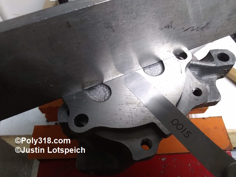
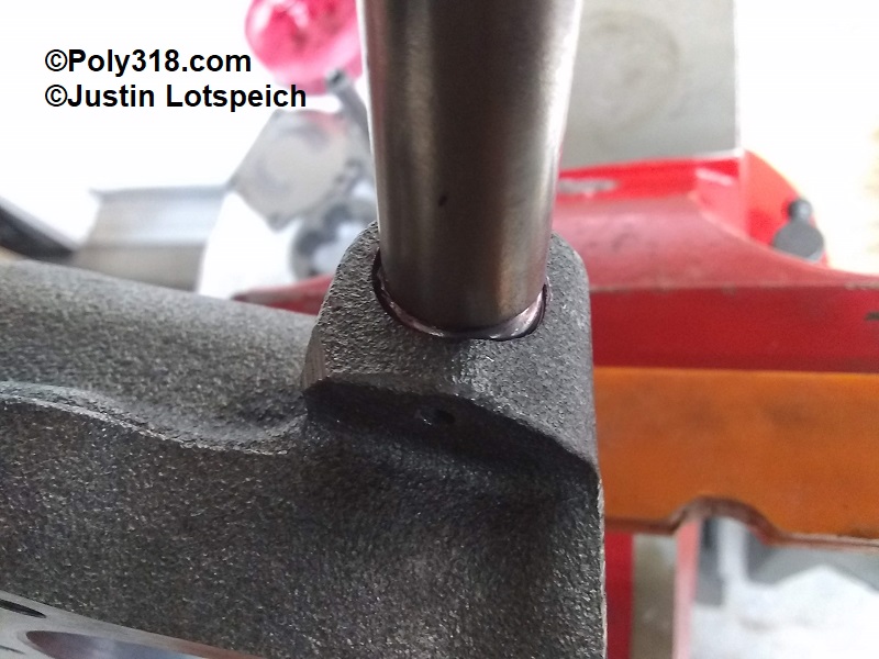
- With the pump secured in a vice with soft jaws, remove the five 1/4″ cover bolts. Flip the cover upside down, wipe off any oil, and place a machinist’s straightedge across the cover. Using a “go/no go” method, check the clearance with a feeler gauge in three spots across the straightedge (Figure 1). Rotate the straight edge in an “X” pattern and check across the straightedge. The gap should be no more than .0015″. If the gap exceeds .0015″, place 220 grit wet sandpaper on a flat surface such as glass and sand the cover in an “X” pattern to plane it flat within spec. In the case of my pump, I could not fit a .001″ gauge.
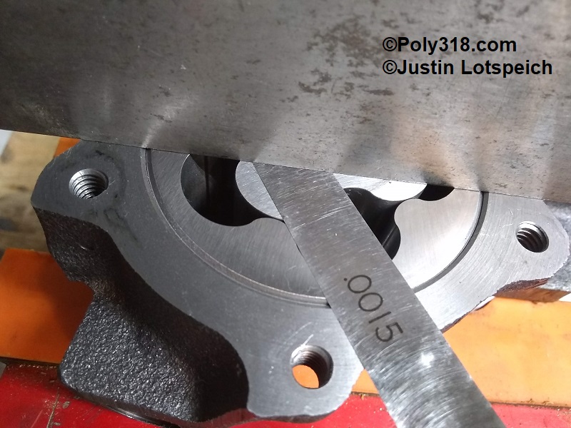
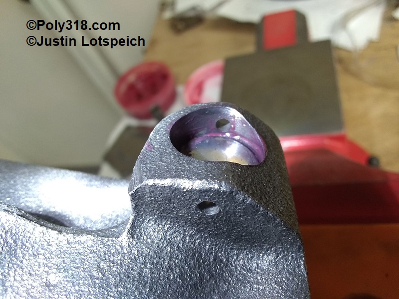
- Remove the inner and outer rotors and wipe off any oil from them and the housing. Reinstall the rotors. Place the machinist’s straightedge across the body, and use a “go/no go” method to check the clearance between the outer rotor and straightedge and the inner rotor and straightedge at the four points of an “X” pattern (Figure 2a and 2b). The clearance should be at least .001″ and no more than .004″. If the clearance is too tight, sand the rotor(s) on the wet sandpaper; if the clearance is too loose, obtain a different pump since the housing is likely machined too deep. My pump measured .002″ for the outer rotor and .0015″ for the inner rotor.
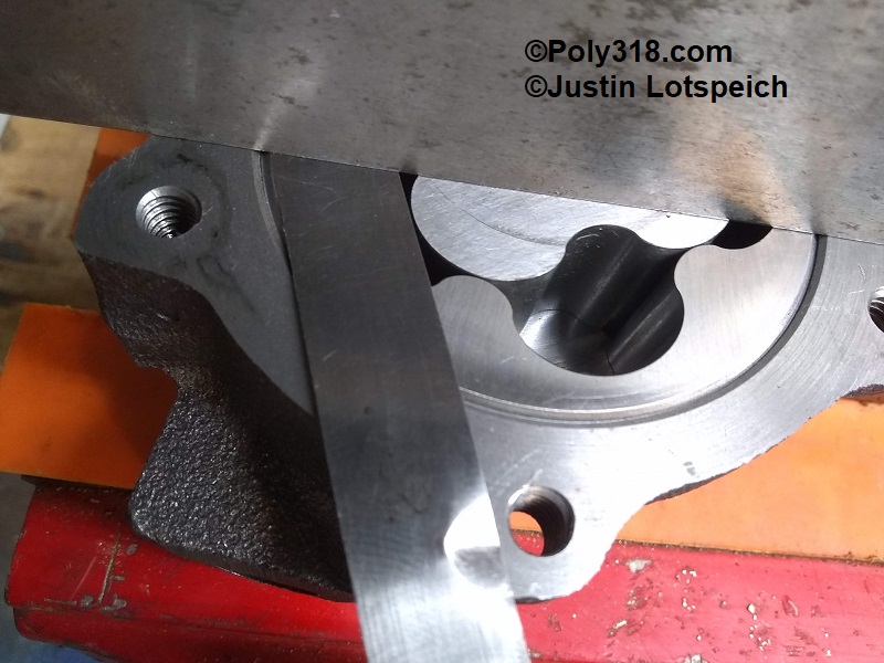
- Using one hand, pinch the inner rotor tight against the outer rotor to one side of the pump housing. Using a “go/no go” method, check the clearance between the inner and outer rotor teeth (Figure 3). The clearance should be between .001″ and .006″. If it is out of spec, obtain another pump. My pump measured .002″.
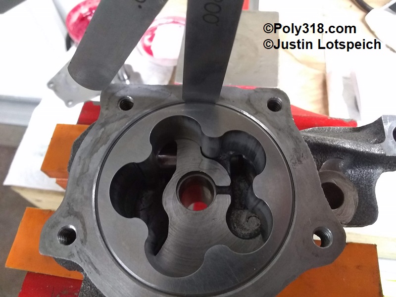
- Remove the inner rotor, and use a “go/no go” method to check the clearance between the outer rotor and the housing wall (Figure 4). The clearance should be between .002″ and .012. If it is out of spec, obtain another pump. My pump measured .008″.
- Lift out the outer rotor and set aside.
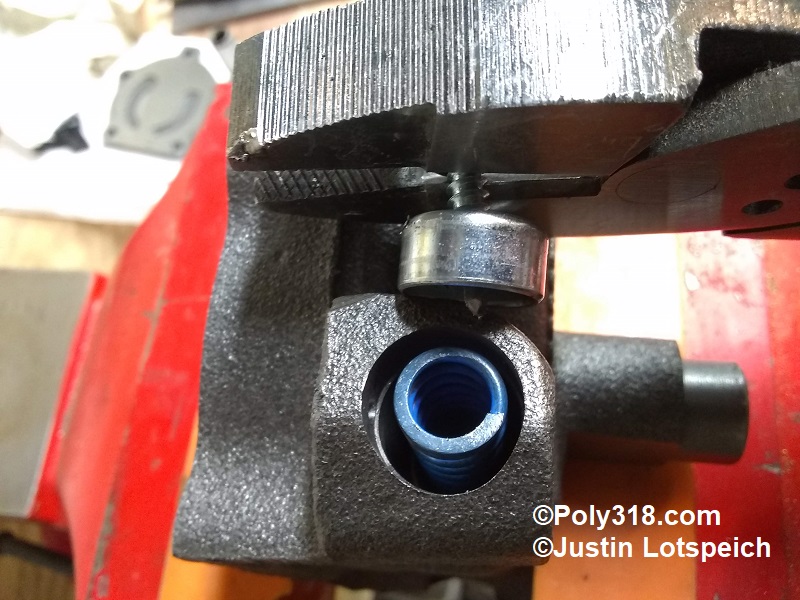
- Remove the pressure-relief spring cotter pin and drill a self-tapping sheet metal screw into the center of the spring retainer expansion plug. Use a pair of pliers to pry out the cup (Figure 5).
- Remove the pressure relief spring and piston and set aside noting the direction the piston installs.
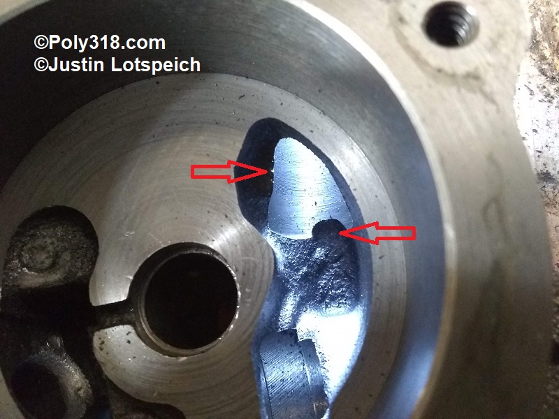
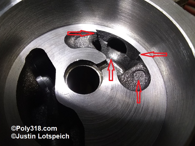
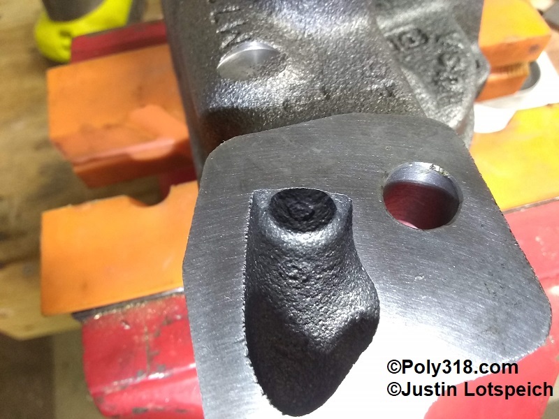
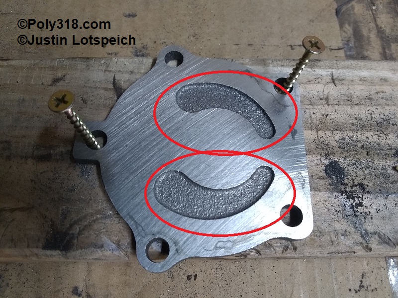
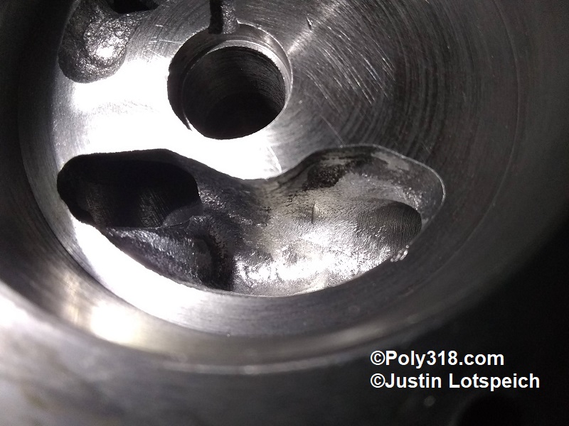
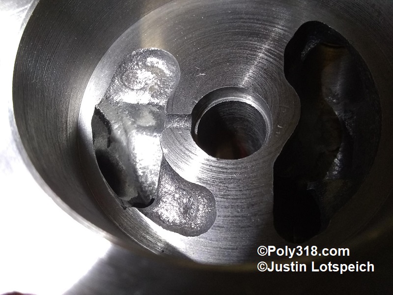
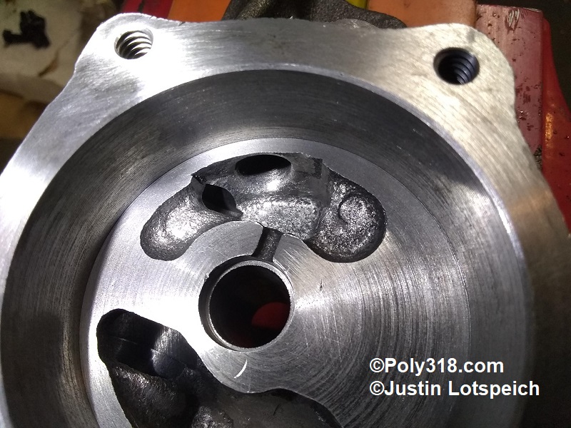
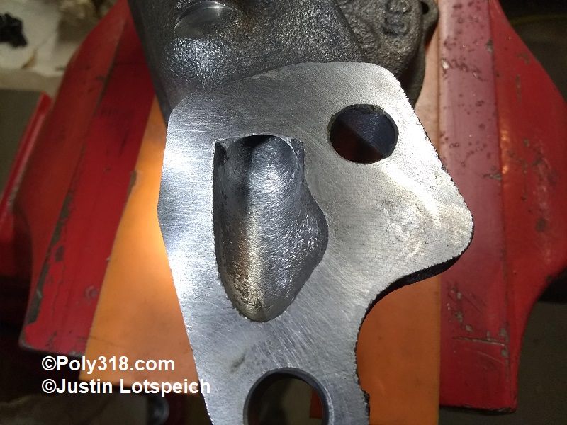
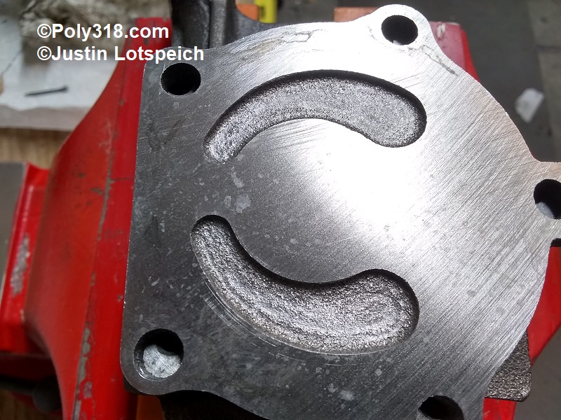
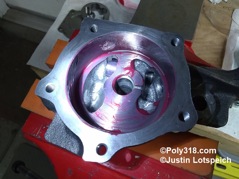
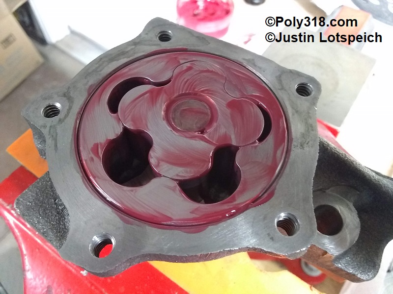
- Inside the housing wells, note the sharp ridges and rough casting surfaces at the pump inlet and the pump outlet (Figures 6 and 7). Flipping over the pump, notice the ridge and rough casting surface where the pump mates to the block main cap (Figure 8). Inspecting the underside of the housing cover, notice the rough casting in the wells (Figure 9).
- Use the ball and tapered point carbide bits to smooth out the ridges and rough casting being very careful not to hit the machined floor and wall where the rotors ride, the cover’s machined surface, and the mating surface of the pump and main cap. (Figures 10, 11, 12, 13, 14). Note the thickness of the casting to gauge how much material you can remove. For example, the housing inlet chamber can be cleaned up a lot, but the outlet chamber is thinner-walled.
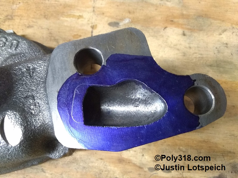
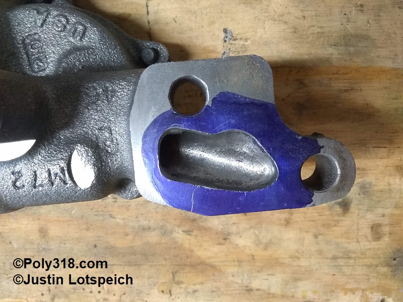
- After applying Dykem blue or similar, trace the pump gasket and port out to the line using the carbide bit, rounding the short turn of the inlet (Figures 15 and 16).
- Obtain a new 5/8″ diameter deep steel expansion plug Dorman 555-011 or Sealed Power 3813052 or similar. Note that the Mopar Performance high-pressure spring kit P3690944 used to include a new plug but no longer does even if the online image shows a plug. The above Dorman and SP 5/8″ plugs are not as deep as the OEM, but it does not matter for functionality.
- After all machining of components is completed, thoroughly blow off/out all the pump components with compressed air, clean in solvent, and blow them dry.
- Working in a clean area, secure the housing in the vice. Lubricate the pressure-relief piston with assembly lube (I use the same Red Line #R0613 I use for engine assembly) and install with the four slots going in first (Figure 19).
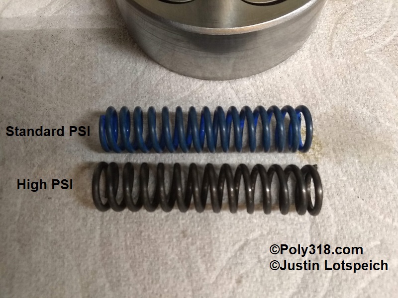
- Install the bare steel, slightly longer high-pressure spring from the Mopar Performance kit P3690944. The blue spring is a spare factory pressure spring (Figure 20).
- Insert the 5/8″ expansion plug with the open end facing the spring. Use a 7/16″ deep socket or drift to drive in the plug just until is passes the cotter-pin holes (Figure 21 and 22). Insert the cotter pin and bend over the end. Warning: Insert the expansion plug into the bore with the open cup facing into the housing. If installed with the cup facing out like a block coolant plug, the spring will be compressed 1/4″ – 3/8″ too much to where the pump will exceed the engine’s allowed oil pressure.
- Liberally lubricate the rotor well’s floor and wall (Figure 23). Lubricate the outside and bottom of the outer rotor and drop it into the housing. Lubricate the inner rotor shaft, teeth, bottom where it rides on the housing floor, and drop it into place. Lubricate the top of both rotors keeping excessive lubricant off the cover sealing surface (Figure 24).
- Place the cover onto the housing, and install the bolts using a dab of blue Loctite. Torque the bolts to 120 in.-lbs.
- Insert a hex wrench into and rotate the inner rotor a few rotations to ensure the pump operates smoothly and to spread the lubricant throughout the unit. I write “HP” (high-pressure) on the cover and spray the outside with WD40 if I will not be installing the pump for some time to keep off rust and to remind me it is converted and ready to install. Bag the pump airtight until it will be installed during engine assembly.
Figures