Classic Car
Positive Crankcase Ventilation (PCV) System
What is Positive Crankcase Ventilation (PCV)?
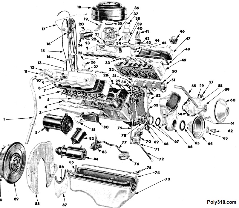
Each time an engine cylinder goes through the combustion cycle, an amount of the exploding gases leaks past the piston rings into the crankcase. This leakage is called “blow-by,” as in it blows by the piston rings. It contains the chemical byproducts of combustion including water vapor and raw fuel along with other compounds you don’t want mixing into the oil. As the blow-by collects in the crankcase, the pressure builds until oil seals and gaskets begin leaking or bursting. Even newly built engines have blow-by, and the pressure builds quickly with worn engines that have more blow-by. To release the blow-by pressure, manufacturers as early as the first gasoline engines used simple breathers to vent the blow-by to atmosphere. Eventually, manufacturers designed a road-draft system where a breather allows fresh air into the crankcase and a road-draft tube extending down to the undercarriage vents the blow-by to atmosphere. Depending on the engine, the road-draft tube is either connected to the lifter valley cover or a valve cover. Figure 1a shows the setup typical for pre-1960 poly A-blocks. The road-draft tube end is often cut at an angle to help create a pocket of vacuum when the car is moving above approximately 45 MPH to help suck the blow-by out of the engine, but below 45 MPH the road-draft system does not produce vacuum and functions as a simple pressurized breather system. Some people refer to the road-draft system as a PCV system, but it only produces positive ventilation at speeds above 45 MPH.
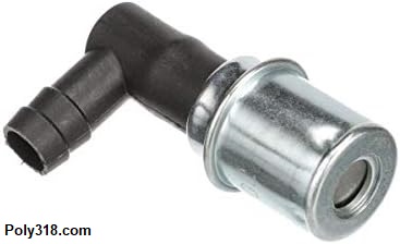
The positive crankcase ventilation system replaced the road-draft tube with a one-way variable-flow valve (Figure 1b) that connects to intake-manifold vacuum. This system maintains suction at all vehicles speeds (though in varying volume of flow depending on the inches of vacuum applied to the valve) to suck the blow-by gases into the intake manifold where they go through a combustion cycle and are vented out the exhaust pipe(s) while constantly replacing the crankcase with fresh air.
History of the PCV System
Partial thanks for the PCV system goes to General Motors and another part to the chemist Dr. Arie Jan Haagen-Smit who did extensive research in the 1940s and published his scholarly article “Chemistry and Physiology of Los Angeles Smog” in 1952. His research confirmed hypothesis that many issues from human health, agriculture, to man-made structures were being damaged by the photochemical reaction of 1,000 – 2,000 tons of hydrocarbons and 200 – 300 tons of nitrogen oxides at the time of the studies. The primary contributor of these hydrocarbons and nitrogen oxides was from the incomplete combustion of the hundreds of thousands of vehicles in the Los Angeles, CA region. Automotive manufacturers began focusing research efforts on the chemicals produced by their vehicles, and in 1958 General Motors Research Laboratories found that about 50% of the hydrocarbons and nitrogen oxides described in Haagen-Smit’s studies were being released through their engines’ road-draft tube that vented crankcase gases including water vapor and corrosive vapors directly to atmosphere. Their research results prompted GM to improve a positive crankcase ventilation system that they first designed during World War II for the M5 Stuart tank and install it in their consumer vehicles. After only a couple years in use, GM found the PCV system so beneficial to both emissions and oil protection that they released the patented design to all US automotive manufacturers free of charge. By 1961 and with no government mandate, the Automotive Manufacturer’s Association voluntarily agreed to and began installing PCV systems on all their California cars. Starting in the 1968 model year, all consumer vehicles sold in the USA had to have a PCV system.
Myth Busting: Is PCV Truly Only for Emissions Control?
When people online ask about retrofitting their vintage engines with PCV or ask for confirmation that they have a PCV system properly set up, inevitably someone comments that the road-draft system “does the same thing as PCV,” that PCV was only developed to satisfy smog laws, and that PCV harms the engine by producing carbon buildup in the cylinder heads and on the pistons. All of these assumptions either over-simplify the history or are myths and don’t take into account how PCV benefits the engine.
Part of these myths stem from the assumption that the PCV system’s sole purpose is for government-required emissions control. Yes, in 1968 USA consumer vehicles were required to use a PCV system, but research since the 1950s proved that PCV systems in fact benefit human health, agriculture, and structures by reducing the toxic, corrosive chemicals and their reactions to other substances that were important considerations for millions of consumers. An important consideration often left out when pinning the use of PCV system solely on emissions laws and important to me as a mechanic is that PCV greatly benefits engine oil by removing water vapor, raw fuel, and other corrosive gasses and compounds from the crankcase before they have time to condense into the oil or bind to internal surfaces forming layers of sludge that further contaminates the oil that passes over the sludge. Motor oil has a hard enough job protecting the components of an engine, and oil is less efficient and breaks down quicker without a PCV system, as proven by many scientific studies of oil. Aside from helping to protect and preserve motor oil, the PCV system removes the road-draft system that anyone who has been under a factory 1950’s vehicle with more than 50,000 miles knows coats the underside of the vehicle with sometimes inches of oily grime after the oil mist mixes with road dust. These engine fumes also dumped out near the firewall, and consumers reported their displeasure of smelling raw fuel, oil, and other blow-by compounds at low vehicle speeds, particularly on engines with some wear on them. Manufacturers had all these facts to consider when developing and using PCV systems.
Research and anecdotal evidence both confirm that running the crankcase vapors through a combustion cycle before exhausting them through the exhaust pipe(s) out the back of the vehicle has no real measurable negative impacts on the engine and its performance so long as the air-fuel ratio, ignition timing and components, and other engine vitals are healthy and correctly adjusted. If an engine’s vitals aren’t healthy or adjusted correctly, the blow-by can have excessive amounts of contaminants that may lead to abnormal carbon and/or oil buildup in the cylinder heads, valves, and pistons when feeding the vapors into the combustion cycle, but the fault here lies in the poor engine vitals, and the lack of PCV would only place all those excessive contaminants directly into the oil.
Does the Road-draft System Actually Perform as Well as PCV?
The short answer is no. The three major drawbacks of the road-draft system are poor ventilation at lower vehicle speeds, coating the undercarriage with oil mist that collects dirt to form thick grime, and introducing blow-by into the passenger cabin at low/no vehicle speeds. A PCV system corrects all of these shortcomings.
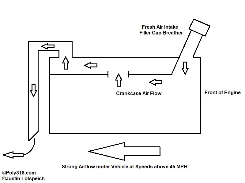
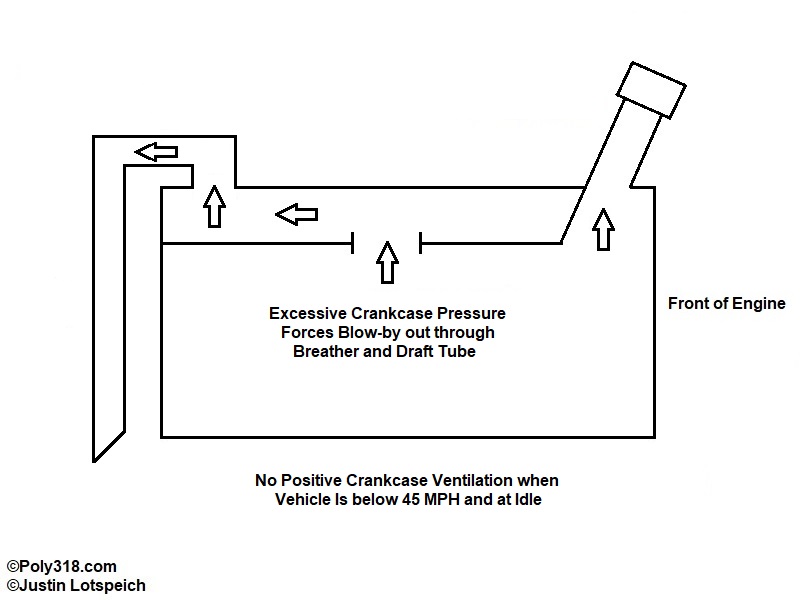
Figure 2 shows a road-draft system performing when the vehicle is traveling at approximately 45 MPH and above. The diagonal tip of the draft tube creates a pocket of vacuum that pulls fresh air through the breather. While the system creates some positive ventilation in this diagram, it is less efficient than full-time PCV because the vacuum is not metered and consistent. Systems like the poly A-block and early B-block that place the breather and draft tube on the valve covers perform better regarding crankcase air circulation but still suffer from the lack of constant vacuum. As soon as the vehicle’s speed drops below approximately 45 MPH, the tip of the draft tube stops producing vacuum, the positive ventilation stops, and the breather and draft tube function like basic breathers that rely on the crankcase blow-by pressure building to the point of forcing out the blow-by at both ends and into the engine compartment where it can make its way into the cabin (Figure 3). A significant issue is that blow-by tends to increase when the engine is at lower rpm because the piston rings are not loaded as firmly against the cylinder walls like they are during higher RPM. As the blow-by and hot oil fumes collect and suspend in the crankcase air, they begin condensing into the oil and onto surfaces as sludge.
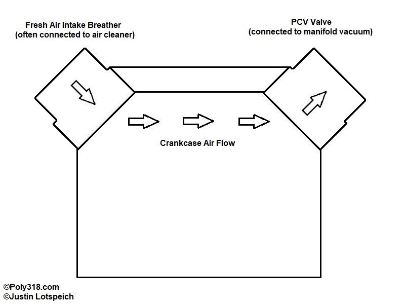
In comparison, Figure 4 shows a typical PCV system on classic vehicles that sustains positive ventilation at all vehicle MPH and RPM to keep fresh air circulating through the crankcase and blow-by exhausting out through the combustion cycle and exhaust pipes.
How a PCV Valve Works
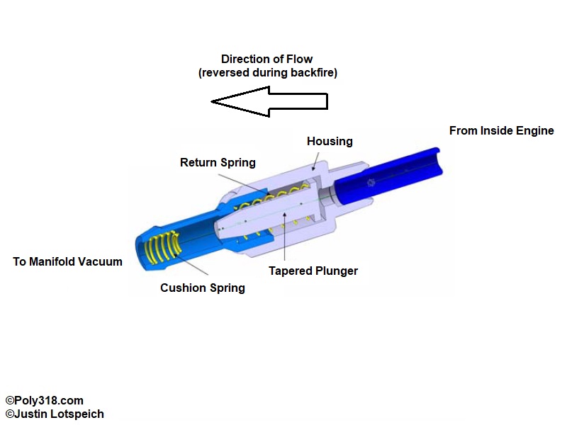
Central to a PCV system, the one-way valve works to control the manifold vacuum and airflow volume under normal operating conditions and to block excessive back-pressure in the rare event of a backfire strong enough to over-pressurize the crankcase. Figure 5 shows the components of the valve. The return spring forces the plunger closed against the inlet port when no vacuum is applied and during a backfire, and the return spring also works to counterbalance the vacuum when applied to the outlet port I mark as “to manifold vacuum.” The plunger is tapered to reduce the volume that flows through the valve depending on the strength of the vacuum signal. The cushion spring stops damage and noise when the plunger is pulled down during high-vacuum such as when slamming the throttle plates closed upon deceleration.
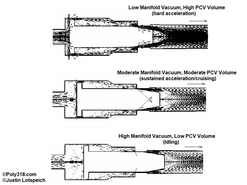
Figure 6 demonstrates the valve in action. At the start of hard acceleration (the top sketch), manifold vacuum initially drops, and the plunger is kept barely open. In this position, the valve flows the most volume to allow enough pressure to escape the crankcase under lower vacuum signal. As acceleration turns into a smoother, sustained RPM, manifold vacuum rises significantly and stabilizes (middle sketch). The valve now has to balance allowing enough volume through to maintain positive ventilation while also limiting escaping vacuum so the engine and accessories have enough vacuum to properly function. The tapered plunger and housing ledge do most of this heavy lifting. At the highest sustained manifold vacuum when the engine is idling (the bottom sketch), the vacuum sucks the plunger down to where the volume is greatly restricted to maintain vacuum for the engine and accessories.
Ideal PCV System for Classic Cars
Without trying to retrofit a vintage engine with a 21st-century PCV system, cross-flow through the valve covers is an ideal PCV system (Figure 7). Ideally, the fresh-air intake breather is located at the end of one valve cover, and the PCV valve is located on the other valve cover at the opposite end fore and aft. With this setup, fresh air flows into one valve cover, flows down through the pushrod and oil drain-back holes in the cylinder head, moves diagonally across the lifter valley, flows up through the pushrod and oil drain-back holes in the other cylinder head, and exits the valve cover through the PCV valve. The vapors then move into the intake manifold downstream the carburetor throttle plates, go through combustion, and exit the exhaust pipes. This routing creates the longest path the fresh air must take to create circulation in the top 1/3 or so of the crankcase to exhaust the vapors and make it harder for contaminants to condense into the oil or to form sludge on surfaces.
Retrofitting a Road-draft System
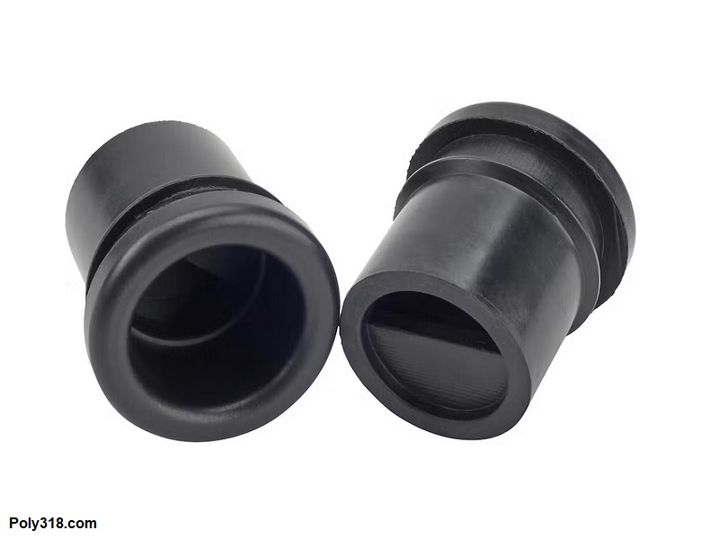
Ideal configurations aren’t always practical, so I want to cover how I would retrofit a road-draft system on classic engines with lifter valley covers, such as on 1950’s Hemi and Hemi-block poly engines. If one isn’t opposed to drilling a hole in each valve coves, the system I describe above can be implemented. Of consideration, the fresh-air breather and the PCV valve should have a baffle installed to stop direct oil from entering them. A sheet-metal baffle can be welded to the underside of the valve cover, or one may use baffled grommets available through suppliers such as Summit, Jegs, and Speedway Motors (Figure 8).
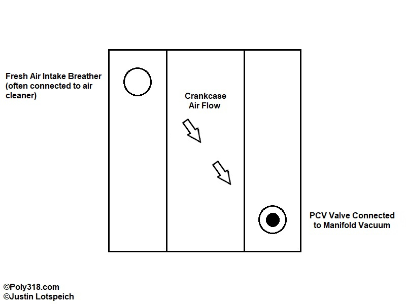
Options are limited for retrofitting an engine without placing holes in the valve covers. The easiest and cleanest way to convert a road-draft system is to utilize the oil filler and the draft tube openings. In this configuration, you should use a quality breather that can be cleaned to cap the oil-filler tube and to serve as the fresh-air intake. The draft tube can be removed and a grommet installed in its place that accepts the PCV valve. A baffle is not required here on most lifter-valley covers like the Hemi and Hemi-block poly because the valley cover has an integral baffle. The PCV valve will need to be fed by manifold vacuum coming off the intake runner/plenum, off the carburetor if it has the provision, or off the port in an aftermarket carburetor spacer. Of note, it is best practice to not tee off the brake power booster circuit if equipped since that circuit should be dedicated only to the booster. For this configuration, the breather should be cleaned during each oil change since it is functioning as an air filter for the fresh air being drawn into the crankcase.
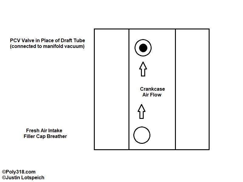
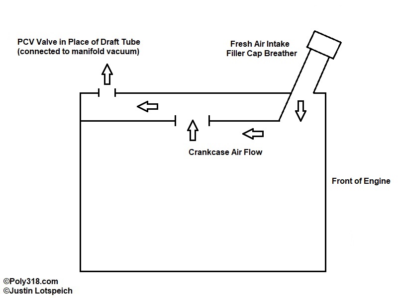
The lack of cross-flow circulation is the downside of this setup compared to one that uses the valve covers. The oil filler and PCV valve are nearly inline, and they are a short distance apart to where the fresh air doesn’t have much room to pick up vapors. Figures 9 – 10 demonstrate how the circulation works.
Conclusion
Hopefully I’ve provided educational content regarding the history of a PCV system, its benefits, and pointers on retrofitting road-draft systems. The benefits to the engine oil, undercarriage, and passenger comfort compared to a road-draft system are well-proven to where the limited amount of work required justifies the modification for me, which I’ve done on my 1956 Dodge coupe build.