Poly 318 Intake Manifold Porting
Introduction
As part of my larger engine-building series, I detail the process for porting performance A-block intake manifolds. The intake manifold can be modified for better flow, carburetor butterfly clearance, and cooler and denser air-fuel mixture. While original equipment Carter WCFB carburetors with their small throttle plates clear the plenum, larger Carter AFB/AVS and Holley 4150/4160 throttle plates will not. For the factory “Dual Fury V-800” dual quad intake I’m using on my 390 stroker, I opened up the plenums to match the Offenhauser 5497 cross-ram adapters and AFB gasket and ported the runners to the intake gasket; I also matched the cylinder head runners to the gasket for a smooth transition from intake to head (see my cylinder head porting article). If I were running a single four-barrel other than a WCFB, I would perform the same procedure using the carburetor base gasket as a template.
Plenum Porting
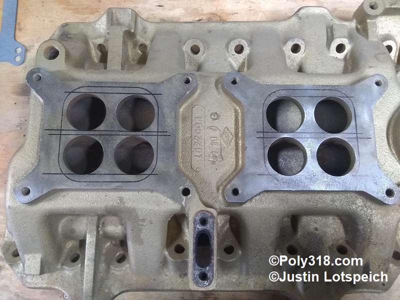
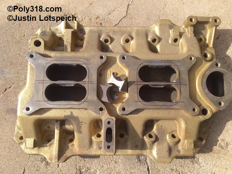
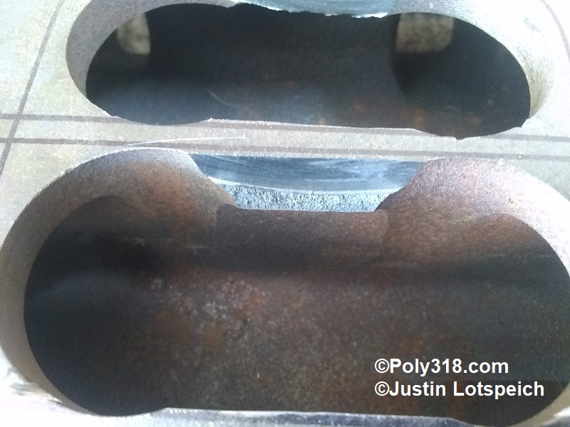
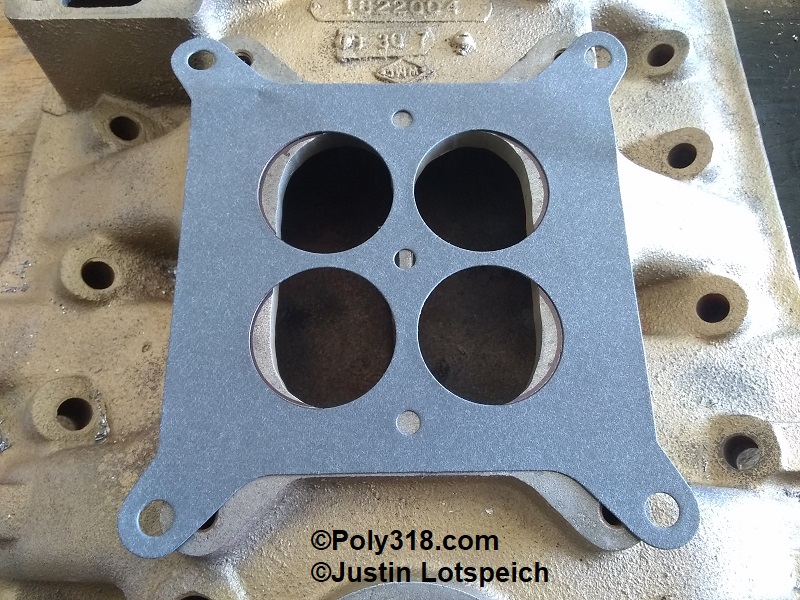
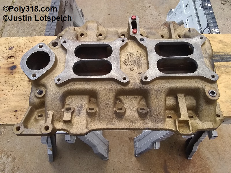
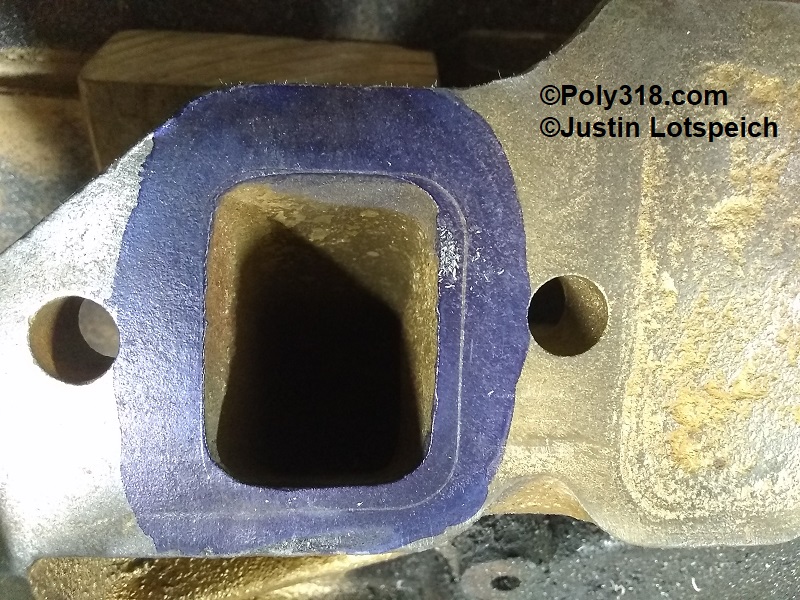
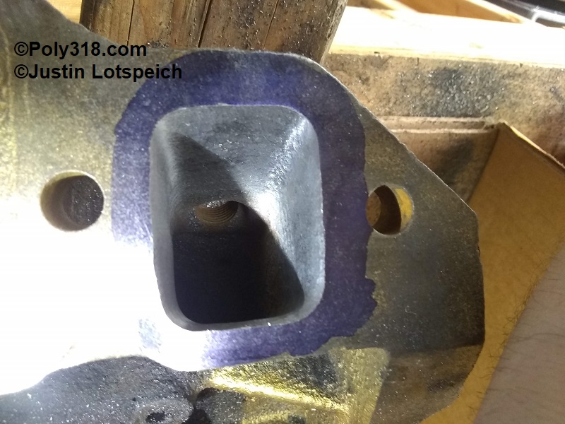
I started with the plenum, using an open-plenum gasket as a template to get an idea of the maximum amount I would ever need to take off (Figure 1). For rough guide lines, I drew a straight line across the factory manifold bores. Using a cut-off wheel, I cut through the plenum as deep as possible. The outside lines cut all the way through, but the thick center did not before the cutting disc hit the ends of the slots. After making the cuts, I lightly tapped the sections down with a hammer breaking the rest of the cut and removed the pieces (Figures 2 and 3). With the cross-ram adapter in hand, I dug through my drawer of gaskets until I found an AFB 4-bore base gasket and found that the adapter bores match the gasket perfectly. I centered the gaskets on the manifold and traced the bores (Figure 3). Using a rounded cylinder carbide bit in a die grinder and a container of water to cool the bit, I elongated the slots to the gasket marks and smoothed the inside edges (Figures 4 and 5). Even though I am running cross-ram adapters on the manifold, I bolted an AFB to each of the plenums and inspected inside with a flashlight while I thumbed the throttle. The throttle plates had plenty of clearance, and the plenum holes are slightly larger than the throttle plate bores to where the air will flow smoothly.
Runner Porting
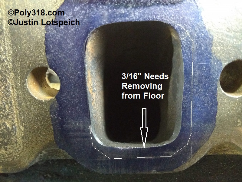
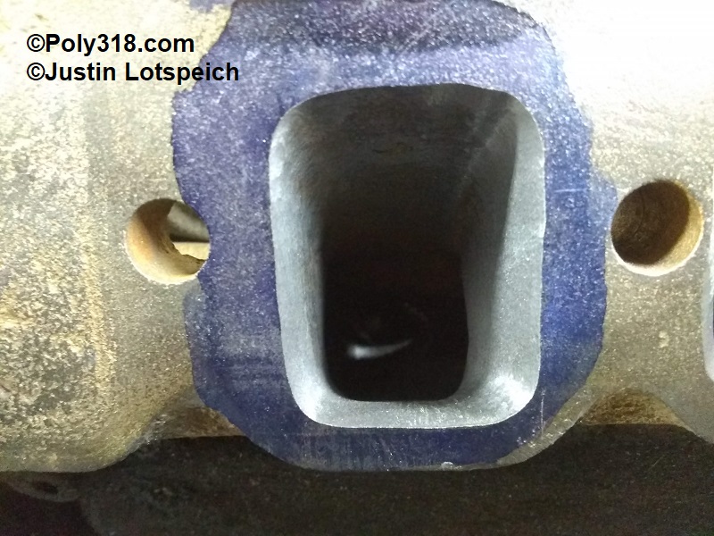
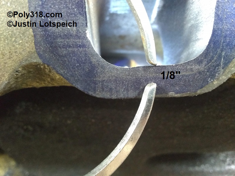
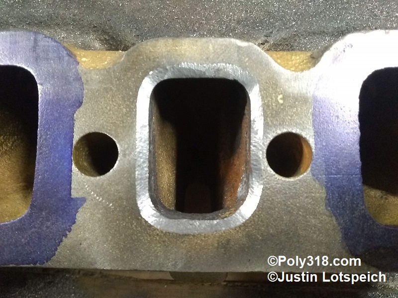
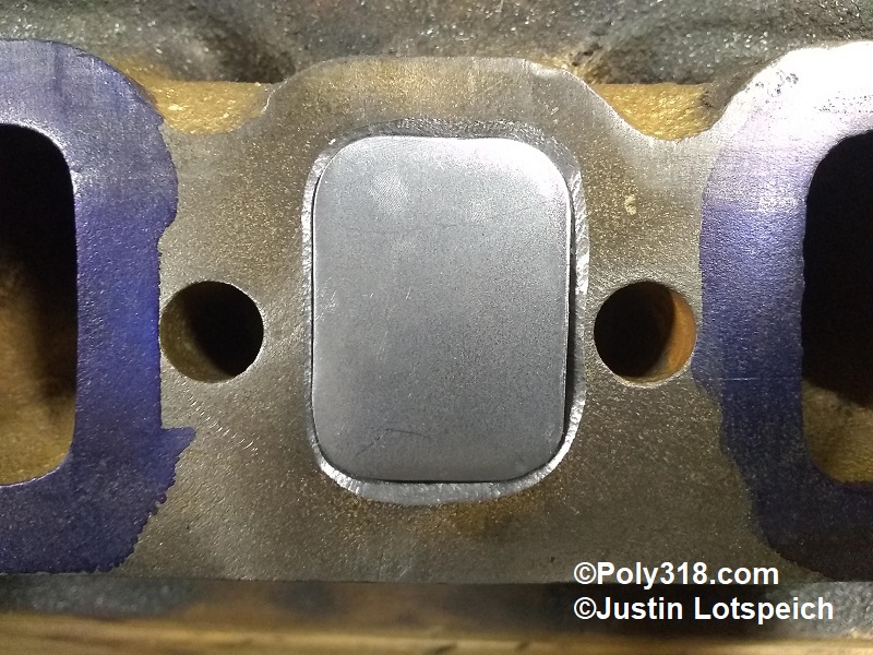
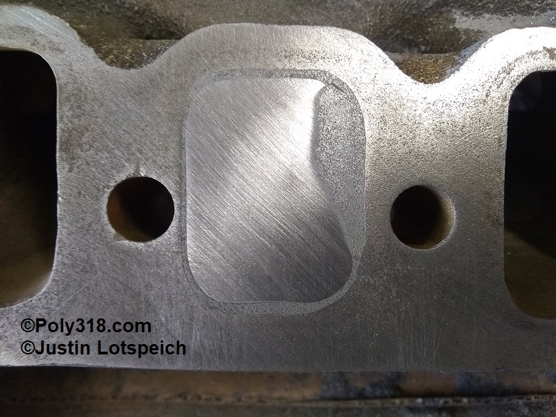
Moving to the runners, I coated the flange in Dykem Blue. Place the gasket on the runners and use 3/8″ bolts to secure it in place. Using a sharp scribe, mark around the gasket (Figure 6). As you can see from the figures below, the intake runners require a lot of material removal with 1/8″ on one side and up to 3/16″ on the floors typical (Figures 7a and 8). Working with a rounded cylinder carbide bit, I tapered the runners from the chamber to the mating flange until reaching the gasket line, working slowly and deliberately to keep the runners as smooth and uniform as possible (Figures 7b and 9). I rounded the transitions from the chamber to the runner floor, walls, and ceiling ensuring smooth radiuses and no casting flash. This particular intake manifold has 5/32″ thick runner floors and walls at the thinnest, so I could not remove 1/8″ or 3/16″ all the way back into the chamber. Instead, I removed the necessary material from the thick mating flange to match the gasket and gently tapered back to where I maintained 1/8″ floor/wall thickness minimum (Figure 10).
Exhaust Crossover Block-off
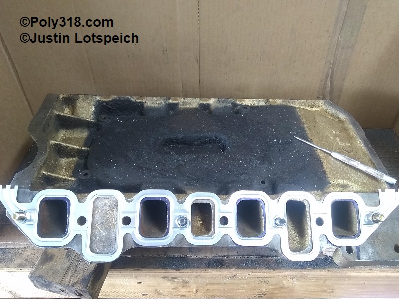
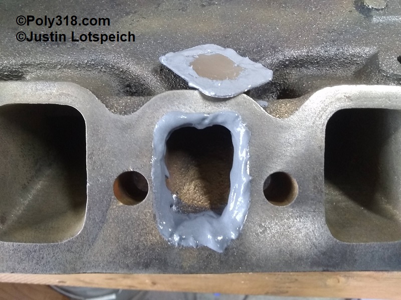
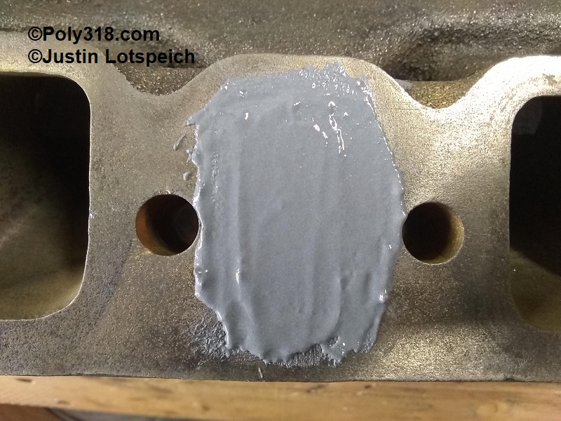
After completing the porting, I blocked off the exhaust crossover. The crossover originally served to actuate the automatic choke’s thermo spring and to assist with driving while the engine is cold by superheating the fuel upon entering the intake manifold. However, cooler fuel packs more power, and factory iron A-block intake manifolds can crack on the floor of the exhaust crossover causing an exhaust leak into the block and a vacuum leak. I had already removed the heat shield by using a cold chisel to knock the rivets loose and a flat bar to pry them up. There is no advantage to running the heat shield with the crossover blocked, so I will not be reinstalling it. I beveled the exhaust crossover ports and cleaned/roughened the first 1/2″ into the crossover (Figure 11a). I cut out plates from 18 gauge sheet metal and radiused their corners so they sat down in the beveled hole (Figure 11b). I scuffed up the plates with coarse sandpaper and washed them with lacquer thinner. Using JB Weld High Heat 37901 epoxy (good up to constant 1,000°F), liberally coat the inside of the port and backside of the plate (Figure 11c). After placing the plate, coat the entire area (Figure 11d). After the epoxy cures, file and finish sand the area smooth (Figure 11e).
Figures