1956 Dodge, Plymouth, Chrysler, DeSoto
Electrical System Redesign and Wiring
Introduction
In the 1956 model year, Mopar permanently went to 12 volt systems in consumer vehicles, and by the 21st century wires are often brittle, insulation is falling off, grounds are corroded and broken, switches need rebuilding or replacing, and the overall system design in far less than optimal for both performance and safety for even the most simplified systems. One example is that my 1956 Dodge coupe has no fuse panel and relies on limited circuit breakers and fusible links to protect the wires, and some wires simply have no protection. When the topic arises of someone wanting to rewire her car, I’ve seen people on forums claim that there’s absolutely nothing problematic with early Forward Look wiring and that any changes are unnecessary. The analogy here is like someone saying there is nothing problematic with driving around in modern traffic in a 1927 Ford Model T with stock mechanical rear drum brakes and no front brakes compared to someone wanting to convert to four-wheel hydraulic drum brakes or better yet disc brakes. Someone can certainly drive around town in a bone stock Model T (I have plenty of times), just like people drive around in Forward Look cars with stock electrical systems, but the fact remains the Model T’s OEM braking system is primitive and limiting. Forward Look electrical systems, too, are primitive and limiting compared to ideal systems, and automotive wiring design changed as manufacturers improved systems and methods.
Another issue that is common on all 1950’s and 1960’s automotive wiring is that the factory undersized wires, designed in large voltage drops, and undersized the generator/alternator where they could to save money on materials and to simplify the design to save time and thus money during manufacturing. Mopar engineers pulled this off usually without issue through a lot of careful calculations and assuming best-case driving scenarios versus worst-case. For those skeptical of my undersizing and voltage-drop claims, hear me out by continuing to read through the following math that proves it. For my purpose of keeping the 1956 Dodge coupe on the road for many decades to come without fear of dimming or flickering lights, shorted wires from loss of insulation, burned fusible links, dead batteries, and the potential of electrical fires, the entire system needs redesigning and rewiring.
Electrical Theory and Design Preface
While I do my best not to go into unnecessary details about electrical theory, I need to explain how I went about designing the system so people can reproduce the steps. I provide a lot of calculations that some people may not be used to considering when wiring a vehicle and the majority of wiring resources online neglect to even mention. These methods are National Electrical Code (NEC) industry standard for designing optimal systems and not just something I came up with out of thin air. I use NEC because there is no governing body for automotive wiring, and the same electrical principles apply to automotive systems. I want to clarify that I wrote this article to walk through designing and wiring a system and not with the purpose of someone simply copying the details verbatim thinking they apply perfectly to their vehicle. Many of my schematics can apply to Forward Look cars with little modification, but one should do all the calculations I detail below for his specific vehicle. I owe a debt of gratitude to my father and my sparky friend Steven who between them and textbooks and manuals they recommended throughout the years have taught me a great deal about working on automotive electrical systems.
Listing All the Loads
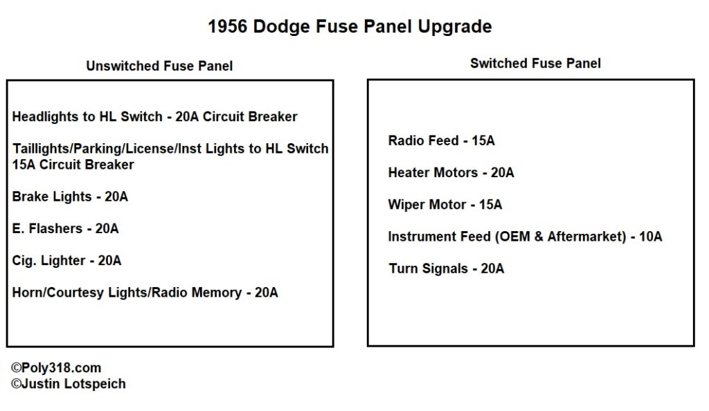
To start the design, I listed all the devices that draw current for my build and then organized them into four categories (Figure 1):
Unswitched Continuous: Elements powered with the ignition switch off and that when used tend to draw current for prolonged amounts of time (e.g. headlights).
Switched Continuous: Elements powered only when the ignition switch is in the accessories or run position that when used tend to draw current for prolonged amounts of time (e.g. instruments).
Unswitched Intermittent: Elements powered with the ignition switch off and that when used tend to draw current for limited amounts of time (e.g. brake lights).
Switched Intermittent: Elements powered only when the ignition switch is in the accessories or run position that when used tend to draw current for limited amounts of time (e.g. turn signals).
Calculating and Listing Load Amperage
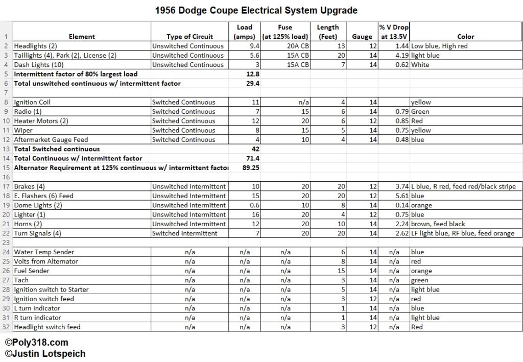
With my list of loads, I researched the actual amperage each of the loads draws making sure to include all bulbs and devices I am using. I cannot simply guess here and need to discover the actual amperage of the exact parts I’m using because small differences in amperage add up to large mistakes in calculations. As you can see from Figure 1 in the column “Load,” these numbers combined are a lot of amps, which is why I use the above categories to help calculate exactly how many amps my system under normal use will require from the alternator to keep components energized and the battery fully charged. For example, if I didn’t break elements into the categories, I would find that my system draws a total of 120.6 amps! My system is almost bone stock aside from adding two more brake and taillights (I explain this modification later), a slightly more powerful electronic ignition system, and some aftermarket gauges that total less than 12A added to the OEM system. If I added an electric cooling fan, power windows, and air conditioning, I would quickly approach a total of 175 amps. So I need a 120A alternator, right? No. I would only need such a large alternator if I normally used every single device at the same time, which I and most people will never do. Instead, to calculate the alternator amperage requirement, there is some more math involved.
First, I add up all the continuous loads including both unswitched and switched. In my case, they equal 60A. These will be the most commonly used devices that tend to draw current for prolonged amounts of time. Next, I look at my list of intermittent loads and find the largest, the 16A cigarette lighter. I take 80% of that load (16A x .80 = 12.8A) and add it to my total continuous: 60 + 12.8 = 72.8A. But I’m not done since a 72.8A alternator would only keep the battery charged and have no room to spare. The system needs a buffer to deal with those times when more intermittent loads are activated like the brake lights and turn signals, so I multiple the 72.8A by an overrating of 125% to get 91A (72.8A x 1.25 = 91A). For a healthy, optimal electrical system using the components I have listed in Figure 1, my alternator must supply at least 91A, so a 100A Mopar alternator will work perfectly.
The OEM Electrical System Is Undersized from the Factory
Now that I’ve gone through the math I used to calculate the power required from the alternator, I want to address any skepticism that the almighty Forward Look engineers would dare to purposefully undersize their systems. If you check my math and do the math on your own Forward Look, you will find that even my bone stock 1956 Dodge requires approximately 48A from the generator just to equal the output when all continuous loads and 80% of the largest intermittent load were used. Maybe someone will scoff at this claim and say there is no way all continuous loads would be on at the same time, but it’s not a farfetched scenario to see someone driving down the road on a cold, rainy night with the high beams on (which means the taillights, license plate lights, and instrument lights are on), radio humming oldies softly, heater motors keeping the windshield defrosted and cabin warm, and wipers clearing the windshield. If you add up all those loads with the other continuous loads (e.g. ignition system, gauges, etc.), you get approximately 48A on my bone stock 1956 Dodge. Do the math on a Forward Look with four headlights and more taillights and the amperage jumps even higher. This 48A fact makes Mopar’s decision to use an Autolite VRX6201A generator with 35A output undersized. This example doesn’t include the high voltage drop percentages in the circuits I calculated (keep reading for how to calculate voltage drop) due to the undersized wiring and multi-device circuits Dodge also used. The manufacturer bet on the above scenario not happening often or for a long enough period of time to drain the battery, but if I were to drive the vehicle under this condition for long enough, the battery would die. Even if I had a 50A generator, the system would dip into the negative every time I pressed the brake pedal. A properly designed system should never come close to dipping into the negative with all the continuous loads drawing current. While the OEM system gets the job done in most modern conditions driving to the burger joint on a nice day, it is undersized and not ideal. But undersizing millions of systems and combining devices into less circuits meant a lot of saved money through less copper and hours of manufacturing labor. Since I am already rewiring the entire car, I will correct these issues.
Sizing the Fuses and Wires Needed for the Loads
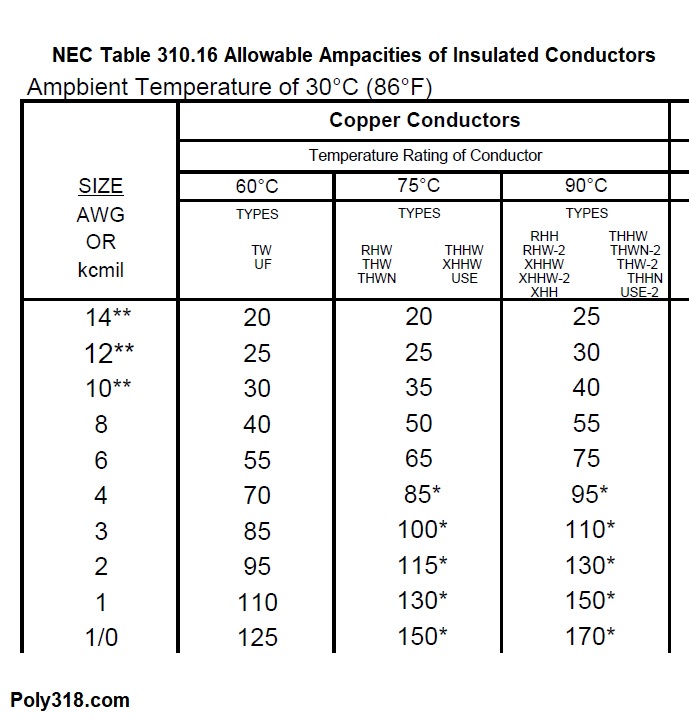
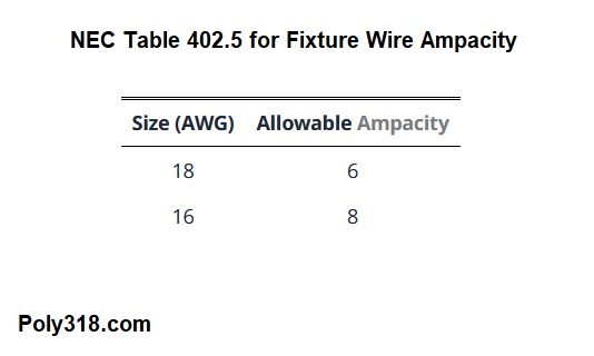
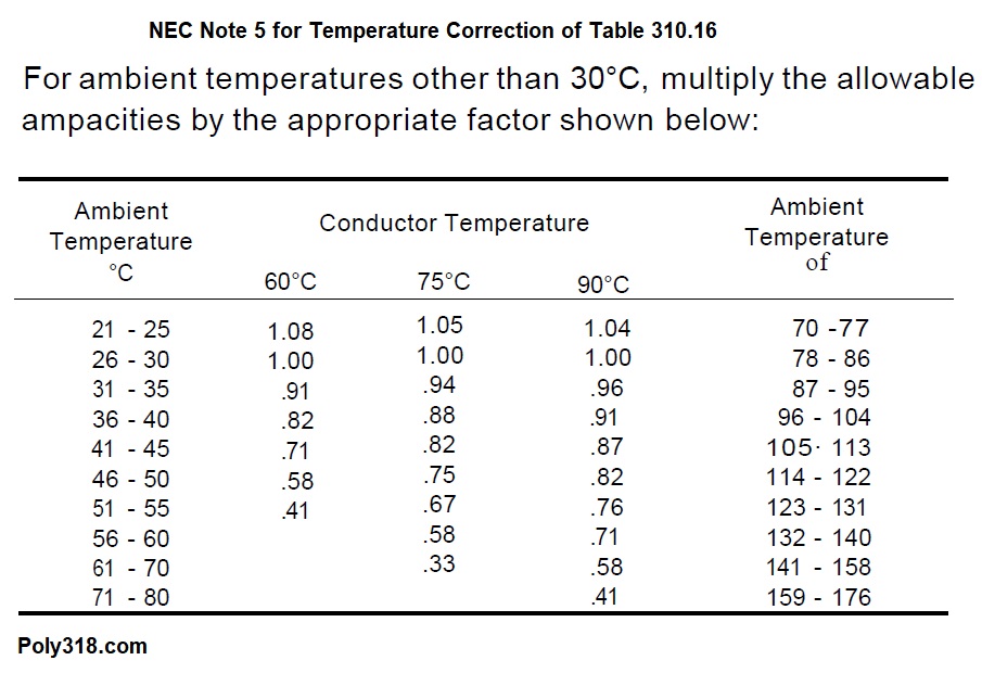
I’ve calculated the amps each load draws (Figure 1), so now is a juggling and balancing act of selecting the best wire to handle the load and the appropriate fuse to protect that wire. This area gets extremely complicated, so I summarize here yet provide charts for reference. Let’s use my heater blower motor circuit as an example. Figure 1 shows that my two heater motors that will on the same circuit draw 12A when on simultaneously. Most people wanting to rewire this heater circuit will do a quick internet search, find a vague chart on some random website stating that a specific gauge wire will handle up to a certain amperage, wire the heater circuit with that wire, and throw in the largest fuse for the maximum amperage. This is a very bad idea since some such charts say that #16 copper will handle 16A when in reality using #16 for a 12A load is a terrible idea. We need to consider the length of the wire, the load, and the safe temperature that wire insulation can reach before we want the fuse or circuit breaker to trip. In Figures 2a – 2d, I provide National Electrical Code (NEC) charts pertinent to designing the system. Importantly I use the 60°C (140°F) ratings in Figure 2a because the automotive primary wire I’m using is rated up to 80°C and almost all terminals used in automotive wiring are also used in NEC-governed industries and rated at 60°C (see NEC 110.14C for more details). It might be tempting to use a higher temperature amperage if the wire insulation is rated like my 80°C, but the terminals aren’t designed for higher than 60°C and must be protected. Remember the note that this maximum amperage is based off an ambient temperature of 30°C (86°F) with allowable amps going down as the ambient temperature rises, so I keep this variable in mind for routing wires exposed to higher ambient temperature like in the engine compartment and focus on routing wires away from heat. For such wires, I use the correction chart Figure 2b. Note that the NEC doesn’t specify #16 and #18 at 60°C in Figure 2a but have the information in table 402.5 Figure 2c.
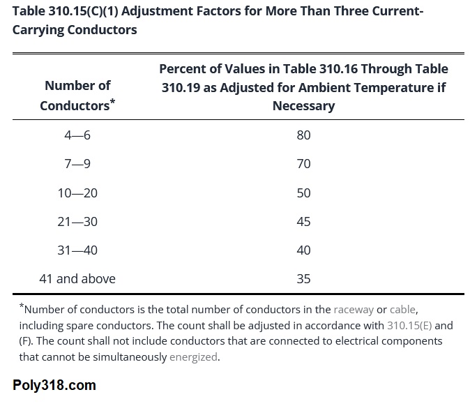
One other important chart is for corrections when bundled wires, like in a taped loom (Figure 2d). To get around having to deal with correcting for bundles, I make sure to build my looms where continuous and intermittent wires are mixed and where wires are separated into smaller looms before they require correcting, especially if the correction requires I go up in wire gauge.
Back to the heater circuit example, according to Figure 2c, #16 copper wire is good up to 8A, so my 12A blower motors will constantly trip that fuse, and if I put a large enough fuse to not trip, the wire would heat up past it’s terminal and insulation rating and could melt insulation and wires and cause a fire. If I had trusted one of those random charts online that say #16 can handle 16A, I’d be in trouble. Looking at Figure 2a, I see that #14 is good to 15A, which doesn’t leave much buffer for my 12A motors considering motors can have inrush amperage upon startup hundreds of times their normal load. #12 handles up to 20A, so it is the best choice. Comparing #14 and #12 wire, going larger will cause no harm so long as the fuse protects the circuit wiring but isn’t too large to where the motor internal wires will burst into flames before the fuse trips.
I know the motors draw 12A and I am going to use #12 wire, so now what fuse do I need for proper overcurrent protection? Remember the fuse’s role is to protect the wire. If the fuse is too small, I’ll get nuisance trips; if the fuse is too large, the wire will fatigue or fail completely before the fuse blows, thus defeating the purpose of the fuse. Because the fuse is not designed to function at its rated limit continuously, I need to make sure to derate the fuse. I can’t simply use a #12 wire and a 12A fuse (if such a fuse existed) since the fuse would be continuously exposed to its limit amperage and would fail. The accepted NEC fuse derating is 80% of the load, so that hypothetical 12A fuse is actually good to 9.6A. The solution is to select a fuse that is a minimum of 125% the load, which is used for things light lights. Electric motors are a little trickier still. Using what I just explained, 12A load x 1.25 = 15A fuse. Unlike a light bulb, motors can have inrush amperage spikes at startup, so it is appropriate to use 150% to calculate the fuse on motors, including the horns: 12A load x 1.5 = 18A fuse. Because there is no standard 18A fuse, it is standard to go up the next size to a 20A fuse. Evaluating these calculations, does the 20A fuse protect the #12 wire? Yes, since #12 is good to 20A according to Figure 2a. If the fuse calculates out larger than the amperage limit of the wire, I would need to go up in wire gauge. In this example, the fuse happens to calculate out to the maximum amperage of the wire, which is fine considering the actual fuse needed is 18A, but this coincidence should not be construed to mean someone should simply design a circuit by slapping in a fuse at the maximum amperage of the wire rather than doing the math to confirm. One caveat here is that I have simplified the selection of fuses for ease of replacement, limiting to 10A, 15A, and 20A when a couple of the original calculations would work with a 7.5A fuse. So long as the fuse protects the wire and will trip before the device smokes, you can simplify the selection.
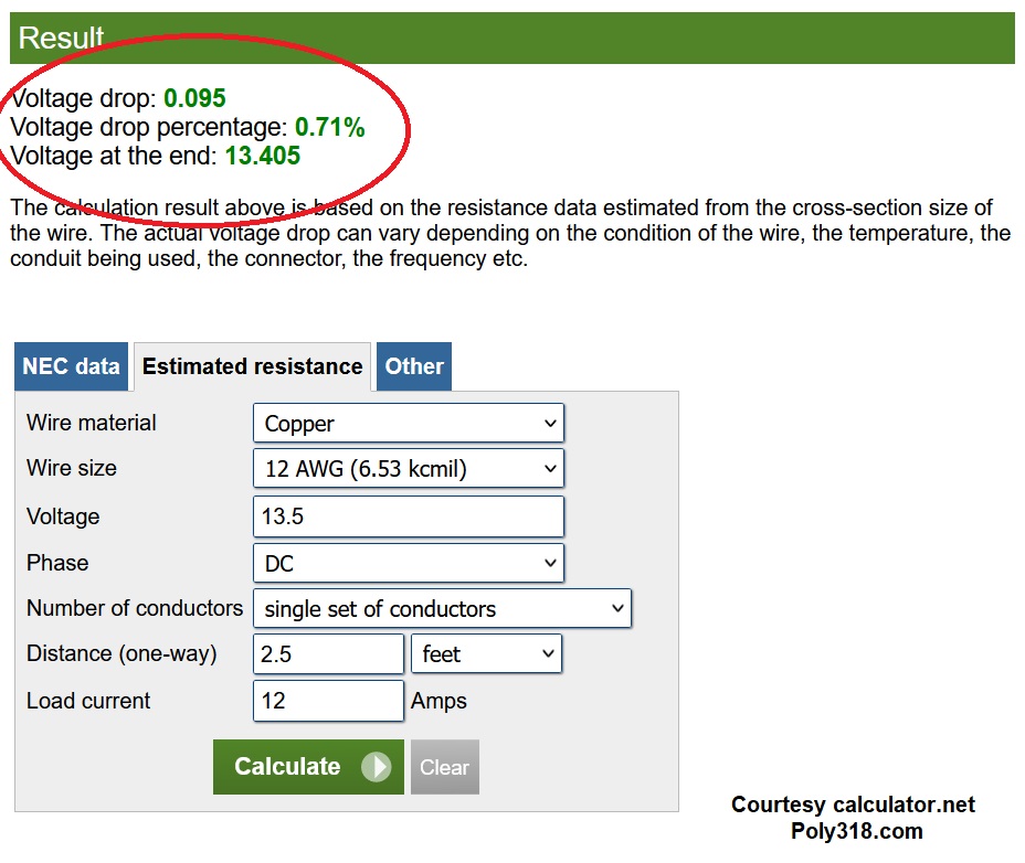
I’m not quite done yet, however. I have the wire and fuse size needed for my 12A load, but now I need to confirm the voltage drop that derives from the length of wire and load. As amperage increases, voltage loss through heat in the wire increases. A motor that gets 12.5V through a 6″ long #12 wire will get 11.93V through a 30′ long #12 wire. Depending on the electrical governing body, acceptable voltage drop can range from 1% up to a whopping 15%. 1% is NASA conservative and 15% too jerry built for automotive wiring. A good middle ground is the NEC’s recommendation of maximum voltage drop up to 5% when combining drop in both the feeder and branches (see 210.19(A)(1) FPN 4 and 215.2(A) FPN for more details). The best way to confirm voltage drop for those who aren’t electrical engineers and aren’t itching to do algebra is a trustworthy voltage drop calculator online like Figure 3. To use the calculator, I plug in #12 copper wire, 13.5V assuming the engine is running, DC, single set of conductors, 12A load for the heater blower motors, and the length. This calculator automatically doubles the “distance” to complete the circuit, so I halve the actual distance. From my fuse panel to the farthest heater motor and then to where the ground wire connects to the body is 5 feet of routed wire, so 2.5 feet in this calculator. The calculator tells me that this configuration will see a voltage drop of 0.71% for 13.405V at the motor, which is great considering my goal to keep drop under 5%. If I increase the wire length the voltage drop increases until I reach 5% where I would need to increase the wire gauge. This voltage drop is crucial for all wires but really comes into play with motors and longer branches such as the brake and taillights. Too much voltage drop can harm motors and will result in dim or even flickering lights.
Since I know this discussion is complicated, I want to run through one more example to summarize what we just read through. Let’s calculate the load, fuse, and wire size needed for my taillight circuit. The circuit includes 16 light bulbs (4 taillights, 2 license plate lights, 2 front parking lights, 10 instrument lights). Below are the actual amperage ratings for each bulb:
Tallights: 4 x .8A = 3.2A
License Plate: 2 x .5A = 1A
Front Parking: 2 x .7A = 1.4A
Instrument: 10 x .27A = 2.7A
Total Circuit Amps: 8.3A
Since the circuit contains light bulbs and no motor, I multiply the 8.3A by 125% to get my minimum fuse size: 8.3A x 1.25 = 10.38A
Because there is not a standard 11A fuse, the correct fuse for this load is the next size up at 15A. Now what wire do I need? #16 is only good to 8A, but #14 is good to 15A, plenty above the 8.3A load. Will #14 supply enough volts to the bulb farthest away from the fuse panel without voltage dropping more than 5%? First, I measure from the fuse panel to the headlight switch and from the switch to the farthest right-rear bulb ground following where I will route the wire. I get 19′ and add another 1′ for wiggle room with routing. Going to the voltage-drop calculator, I plug in copper, #14, 13.5V, DC, single set conductors, 10′ length (remember I must halve the length for this particular calculator), and a load of 8.3A. The calculator spits out that I will see a 3.11% voltage drop and get 13.08V to that last farthest bulb. So my wire is properly sized for the load amperage and length of the feeder and branch wires. My 15A fuse will protect the wire, is at least 125% larger than the load, and is large enough to stop nuisance trips. Every circuit in the car gets this treatment.
Ground Wires (including battery, body, and chassis)
A vehicle’s ground system is imperative to a healthy, safely functioning electrical system, yet it is an often overlooked or misunderstood part. The same sizing procedures covered in the previous section apply to ground wires. Many ground wires look smaller than the power input, but remember that ground wires are often very short compared to power wires, so they can carry the same amount of current with a smaller gauge wire. All grounds should connect to bare metal and be protected from corrosion to maintain continuity.
Many devices ground through their housings, so these attachment points on the device and body/chassis/engine should be bare metal and secure. For devices that cannot ground via their attachment due to having plastic, fiberglass, etc. housings, a dedicated wire should be run from the ground terminal on the device to bare metal.
Three ground circuits are key to a healthy, safe system: battery ground, chassis ground, and body ground. I’ve seen many online posts of people claiming that the purpose of these connections is to ground the engine and body to the chassis, which isn’t accurate. In summary, all primary ground paths lead to the battery through the engine as the largest chunk of metal in the system. What I mean is that the body should be grounded to the engine, the chassis should be grounded to the engine, and the engine should be grounded to the battery. The most significant reason for this design is the starter motor as the highest load in most vehicle’s electrical systems. Keep in mind that some vehicles, like some of our Mopars, use smaller-gauge redundant ground wires from the body to the negative battery terminal, but these smaller-gauge redundant grounds should not be mistaken for the larger primary grounds.
On most classic V8 engines, the starter motor grounds to the engine block or tot he block through the transmission bellhousing/case. As the starter is engaged, a huge amount of current moves from the starter motor into the engine block in search of a path back to the battery. For this reason, the negative battery cable should be of proper size for the load and cable length and connected directly to bare metal the engine block, cylinder head, or bellhousing bolt. For vehicles with batteries on the left (driver) front, a common method is to connect the negative battery cable to the front of the block or cylinder head using an accessories bolt. This connection should be to bare metal and confirmed with a multimeter since cylinder heads are insulated from the block by the fiber head gasket or gasket sealant and ground through the head bolts. When the engine is properly grounded to the battery, current flows from the starter motor, through the block/head, into the battery. This short, direct path along with the proper cable gauge creates the least amount of resistance practically possible and therefore the strongest starter with lower working temperatures for durability and reliability. As an example, for my 1956 Dodge’s system I use an 18″ 1/0 copper welding cable from the battery terminal to the left front cylinder head.
For vehicles with the battery mounted in the trunk, the same principle applies. In this situation, a properly sized positive cable (e.g. a 2/0 copper welding cable) runs from the positive terminal to the starter motor (or remote solenoid), and another cable of the same gauge runs from the negative terminal to the engine. Some people will tack a shortcut to save $100 on cable and use the chassis to carry the starter current back to the battery, but it is unwise to run a short cable from the terminal to the rear chassis and another cable from the front chassis to the block because there is much more resistance in the chassis route than a cable connected directly from the battery terminal to the engine. Using the chassis might work in some situations, particularly when the weather is cool and components cold, but the starter may struggle or not even be able to turn over the engine when the components are hot, and the starter motor will likely wear out quicker due to the additional strain. The sure-fire method to keep the electrical system happy and not be stranded at a burger joint on a hot day is to run a dedicated ground cable from the engine back to the battery.
The two other crucial grounds are for the body and chassis, which should connect to the engine. These grounds can use either a cable or strap and must be sized for the current running through them. Ideally for troubleshooting purposes, the two grounds will connect to the engine at the same location as the battery cable, but the body ground often presents issues here since it would require a long strap/cable to go from the firewall to the front of the head. For my 1956 Dodge system, I run a 12″ #4 copper welding cable from the battery cable bolt in the front of the left cylinder head to a 1/4″ bolt in the left chassis frame rail, and I ran a 6″ #4 copper welding cable from the firewall to an accessories bolt hole on the back of the left head. Additionally, it is wise to place a second body-to-chassis ground at the rear of the vehicle. For the 1956 Dodge, I ran a 6″ #4 copper welding cable from the floor of the trunk to the left rear frame rail. This ground provides a second path for the current of rear lights and any rear electronics grounded to the body to get to the engine and from there into the battery via the left frame rail, which might be a path of less resistance than going through the body and if so results in brighter, constant rear lights.
So why does all this specific routing even matter? When people online have asked for advice about where to connect the negative battery cable, I’ve seen responses to connect it to the chassis or even to the radiator core support, which is the body. This practice is a recipe for problems starting the engine and a possible fire. Here’s what happens if one connects the negative battery cable to the chassis or body. Let’s assume the body-to-engine and chassis-to-engine grounds are #4 straps, which often isn’t the case and many times one or both of those ground straps is missing completely. Remember that those straps/cables are much smaller than the battery cable because they are sized to carry lower current from devices grounded to the body or chassis, such as gauges, heater blower motor, etc. You crank the starter. Where does the current go in search of a ground? It cannot go through the engine straight to the battery since there is no cable tied from the battery to the engine. Instead, the massive amount of current is forced to travel through the block, through the small body or chassis ground strap, through a section of the body or chassis over to the battery cable, and through the battery cable into the battery. Between the resistance in the small ground strap and in the path through the body or chassis, the starter will struggle far more than it needs to and might not be able to start the engine when the engine and starter are hot. There will also be some much current trying to cram its way through the smaller-gauge strap when it really needs the room of a 1/0 cable that the strap melts causes an electrical fire followed by a gas fire after the fuel pump hose burns through. Now, if the 1/0 battery cable is attached to the engine, the starter current flows through the block, through the cable, into the battery, and never enters the body or chassis. Everything is properly sized, the electrical path is one of least resistance by design, the starter is happy, and things stay cool and fire-free.
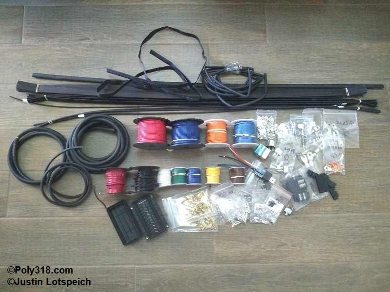
Wire Color Selection
Once I am comfortable with all my circuits and the design of their feeders and branches, I deal with selecting colors. There are two methods here: economical and extravagant. Quality automotive wire isn’t cheap, and it is often difficult to find less-common colors in spools under 100′. If money is of no concern, there are enough colors and color-stripe combinations to have a different color wire for every feeder and branch wire in my build. For me, I don’t mind spending money on quality parts, but I’m okay doing more design work to use a more limited wire color pallet instead of having many 100′ spools of striped wire of which I only need 2′.
Because my system uses a GM turn signal switch loom and connector, I start my coloring using most of these factory GM connector colors for constancy and build the color scheme from there. I focus on not running the same color wires to the same switch/relay/device or in the same loom. For example, I don’t want to run two #14 blues to the headlight switch since I would not be able to tell which wire goes to which terminal. Similarly, I prefer to not run two #14 reds in the same loom in the event I ever need to troubleshoot an issue. This process takes a lot of time and revision, and I type the colors into a column in my spreadsheet for ease of changing/tracking. Remember to include all the branch wires such as those that run from gauges to senders or trigger wires for relays.
Once I am comfortable with the colors, I make another column (not shown in Figure 1) for the spool lengths I need to check to see if I have or need to order. I go down the list of circuits and look at the lengths of the wires for all the circuits that share a color. I purchase most of my wire and terminals from Del City who have a limited color selection of 25′ (#14) and 15′ (#12) “thrifty spools” and a wider selection of 100′ spools. Any color that has more than 20′ on my list, I note that I need a 100′ spool. Anything below 20′ I note a 25′ spool.
Fuse Panel Selection
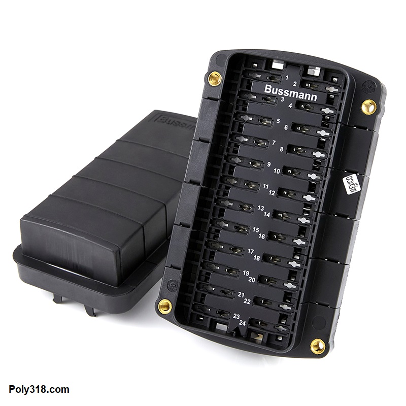
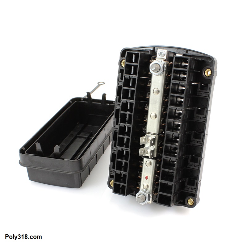
I have the list of all my circuits, so I now need to find a fuse panel that will both accept enough circuits and allow me to have some of them unswitched and others switched. In my case, I need two fuse blocks that do not share the same power feed. One panel will be always hot even with the ignition switch off and the other hot only when the ignition is turned to accessories or run. I could use two independent fuse blocks or a single panel that has a split-bus configuration. Because I have limited room with the fuse panel in the left kick panel, I researched long and hard until settling on an Eaton Bussmann 15713-24-12-22 panel (Figures 4a – 4b) through a specialty supplier that accepts ATO/ATC fuses and circuit breakers and has 12 circuits on one bus, 8 on another, and four on yet another with spade connectors on the back for power. I will jumper this 4-fuse section to lug of the 8-fuse bus to get 12 fused on the same feeder. The panel also takes 1/4″ threaded lugs that will work well with my higher amperage requirements and larger feed wire compared to a fuse block that will accept up to #10 wire crimped. This particular fuse panel requires Pack-Con female connectors 12020321 (#14 – #16) and 12020400 (#12).
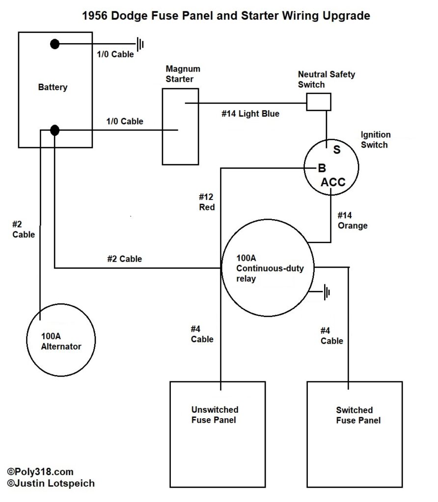
Fuse Panel Power Design
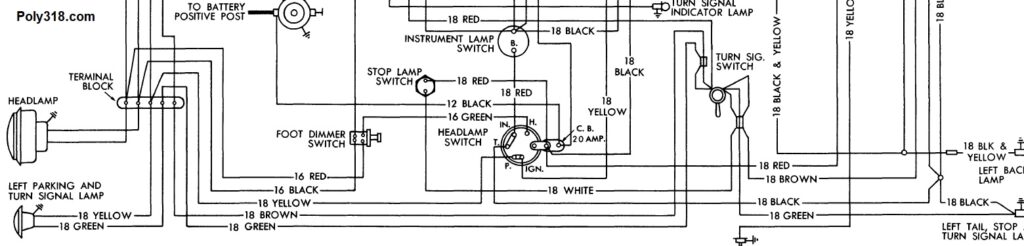
Now we’re getting into what most people think of when talking about designing an automotive electrical system: schematics. In reality, the bulk of the work is many hours of sorting all that I’ve discussed thus far. How do I get one fuse block to be powered constantly and the other powered only when the ignition switch is on accessories/run? Traditionally, many automotive manufacturers relied on multiple switches to perform this function for circuits. Using the factory 1956 Dodge headlight switch as an example, a hot goes from the battery to the headlight switch so the switch has constant power regardless of the ignition switch position. Turn the headlight switch to “park” and the taillight, parking light, license plate light, and instrument light branches energize. Turn the switch to “run” and the taillight, license plate light, instrument light, and headlight branches energize. The problem with this design is that the switch ends up having a lot of current flowing through it–16.6A to be precise–which puts stress/wear on the contacts and creates heat. The other issue is that all these branches are fed by a single feeder protected by a 20A circuit breaker, so there is a high percentage of voltage drop, and if the circuit breaker trips all the car’s lights go dead. For 1956 technology and Mopar’s accountants, this system was acceptable, but it’s not ideal.
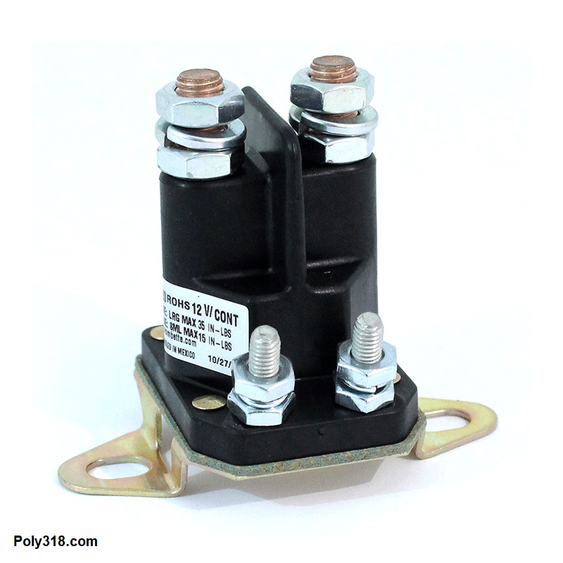
Rather than relying on multiple switches to do the work, I use a 100A Trombetta 784-1221-020-02 continuous-duty relay designed to handle the heavy load (Figure 5a – 5b). The wire sizes up to the fuse panels are crucial because any voltage drop here will impact all circuits downstream, so bigger and shorter is better. Since I am using a 100A alternator, I calculated with the different NEC charts and the voltage-drop calculator that it is best to use 1/0 positive and negative battery cables, #2 cable to run from the alternator to the battery and from the battery to the main relay (8′ long after routing), and #4 cable feeds from the relay to the fuse panel lugs with 1/4″ diameter terminals (10″ long each after routing). For quality and price, I use industrial welder cable that can be had at a good welding supplier or online. The relay has a #14 ground to the body and a #14 trigger that goes to the “accessories” terminal on the ignition switch. How does this all work? One of the fuse panel buses is fed off the same side of the relay where the #2 battery feed attaches, so that side of the fuse panel will always be hot as long as the battery is connected. The other fuse panel bus is fed off the normally open side of the relay lug that is dead when the ignition switch is off. When the ignition switch is turned to accessories/run, current flows down the #14 trigger wire and closes the relay allowing current to flow to the other fuse bus. As long as the ignition switch remains on accessories/run, this side of the fuse panel is energized. This design puts the strain on the main relay, which in my case will easily handle the 72.8A continuous load I’ve calculated above.
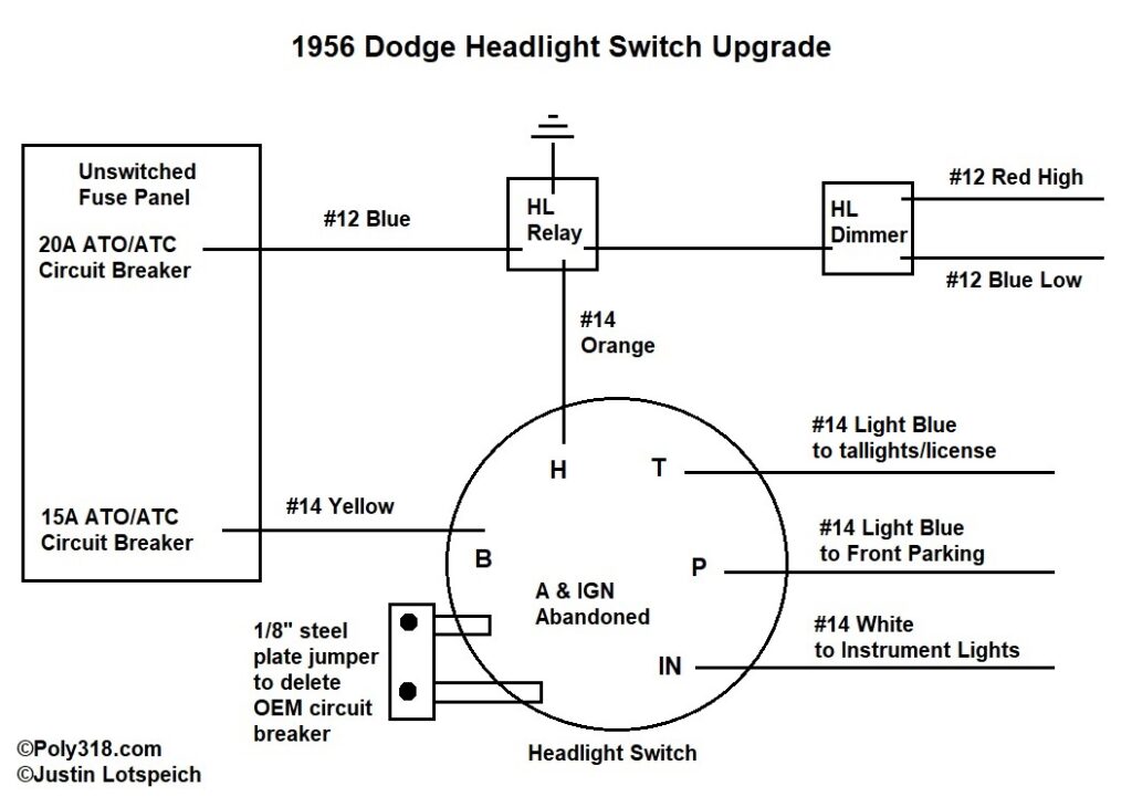
Headlight Switch Modification and Circuit
The 1956 Dodge headlight switch, as with many Forward Look headlight switches, is an unavoidable oddball. If the switch were a typical rotary switch with knob sticking out of the dash, I’d simply install a 1970’s GM-style headlight switch that has many wonderful features and makes wiring a breeze and fit the ’56 Dodge knob. However, the ’56 Dodge switch is mounted sideways with a crank that converts the vertical lever action into rotary action, so I’m stuck with the funky switch. As I pointed out earlier, the issue with this switch is that it crams all of the car lights into a single circuit forcing 16.6A through the switch putting strain on the contacts and causing unwanted voltage drop to the longer light branches. Figure 6a is one of my solutions and the one with which I’ve gone. I want to centralize all fuses and circuit breakers at the fuse panel for ease of access and troubleshooting, but the switch has a 20A circuit breaker bolted to it necessary to complete the circuit. To move this circuit breaker into the fuse panel, I replace it with a 1/8″ steel strap and place two ATO/ATC circuit breakers in the fuse panel. The headlights are now powered through a relay whose trigger goes to the “H” terminal on the switch. When the switch is turned to “run,” a small amount of current flows through the trigger wire and closes the headlight relay allowing full 9.4A current to flow directly from the fuse panel through the headlight dimmer switch to the bulbs. The switch now has to handle only the current for the taillights, license plate lights, parking lights, instrument lights, and headlight trigger protected by another 15A circuit breaker. I completely abandon the “A” and “IGN” terminals and run those lights through the fuse panel.
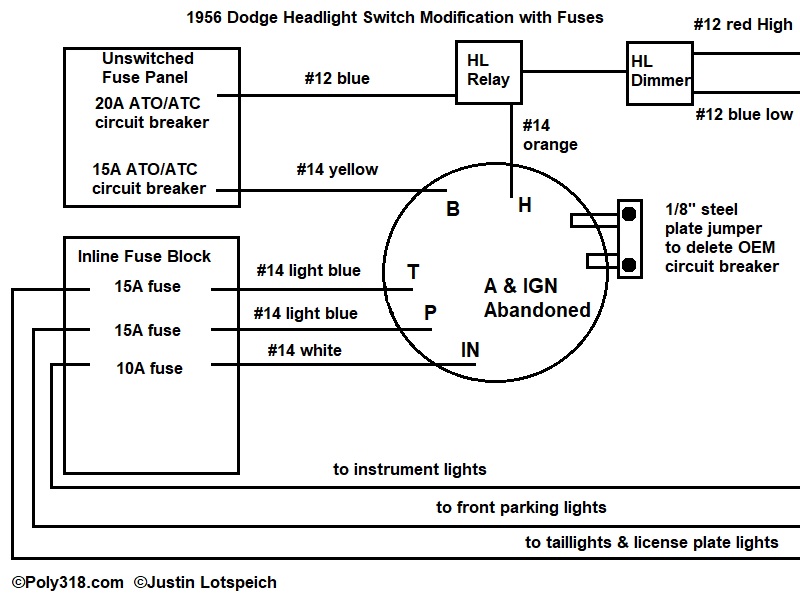
Another option (Figure 6b) is the same design only instead of the branches running directly from the switch to the devices the wires first run through an inline fuse block. By using this routing, the branches from the inline fuse to the devices are fuse protected. While I was tempted to use this configuration, it requires more room in the kick panel for the inline fuse block, which I don’t have to spare, and adds a couple extra feet and thus voltage drop to the branch wires.
Some readers might ask why I used a 15A circuit breaker for the other lights versus a fuse? That circuit still powers the trigger for the headlight relay, so if I used a fuse and it blew, I would lose headlights until I replaced the fuse. In the Figure 6a configurations, if the taillights, license plate lights, or instrument lights ground out, the 15A circuit breaker will heat up and trip, killing all the lights, and then come back on once it cooled allowing more safety when driving at night. However, a similar situation would not happen if something grounds out in the headlight wiring since the 20A circuit breaker would trip and kill the headlight power while leaving the other lights on providing more safety at night. In the Figure 6b configuration, if the taillights/license plate lights or instrument lights ground out, the specific branch inline fuse will trip before the 15A circuit breaker, leaving the headlights on. The benefits to either of the configurations are that I have moved the circuit breaker to the fuse panel, have decreased voltage drop to all the lights, have lightened the current workload of the switch, and have increased chances I will either have taillights or headlights if the circuit has an issue and a breaker trips. When I calculated the factory headlight switch configuration, I found voltage drop above 5% that would impact the brightness of all the lights on “run” including the headlights and taillights. Complicating that issue, I have converted the two backup lights into taillights/brake lights for better night visibility (four tail/brake lights are plenty bright to see while backing up anyway). I am flowing another 1.4A through the switch and increasing voltage drop to the other lights in the circuit. With this modified configuration, I have a meager 1.44% voltage drop to the farthest headlight on high beams and 4.19% to the farthest right-rear taillight.
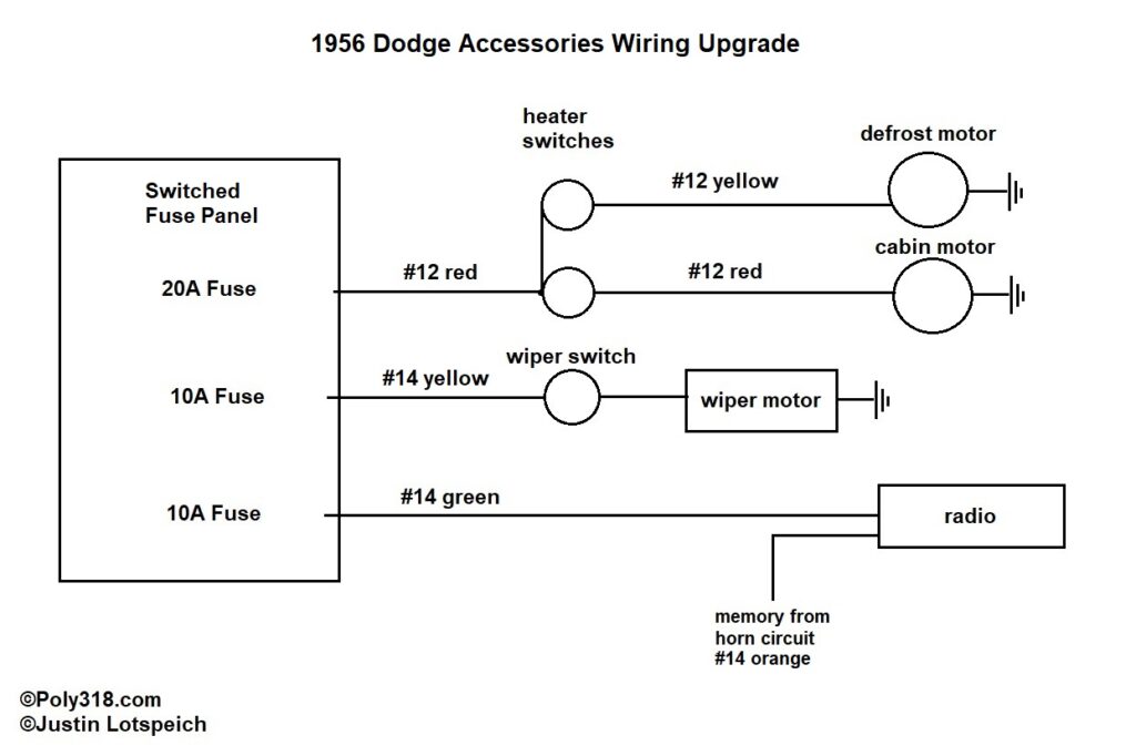
Accessories Circuit
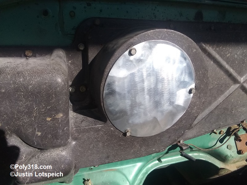
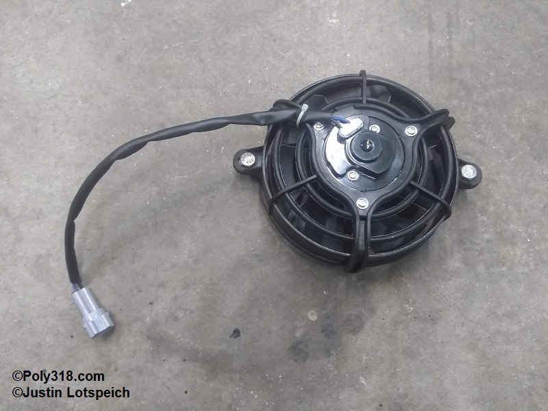
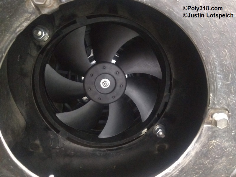
The accessories circuit is pretty straightforward (Figure 7). The two heater motor switches are powered off the same circuit. One area I modified was removing the larger cabin blower motor and built a block-off plate (Figure 8a) because it protruded too far into the engine compartment and hit the carburetor on the cross-ram intake setup. I installed a 2.5A motorcycle radiator cooling fan that flows 450 CFM to push air into the heater box (Figures 8b – 8c), which is why this circuit load is only 12A. The wiper motor is on its own circuit. I have added a modern, simple Bluetooth/USB stereo into the glovebox powered off the switched fuse panel with a memory feed branching off the unswitched horn circuit. I’m still deciding on the speaker situation but am leaning toward just one speaker behind the dash grille but may put two more speakers in the doors or kick panels if I have room with the fuse panel. The intent of the stereo is for something to listen to when sitting in line at the drag strip or while eating at the drive-in. The engine and exhaust will be too loud to bother using the stereo while driving, which is why I’m leaning toward the single speaker to keep the sound “vintage.”
Instrument Circuit
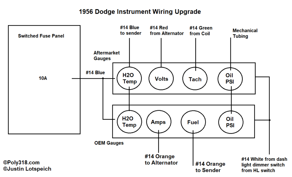
The instrument circuit gets some additional gauges while maintaining the OEM gauges (Figure 9). All gauges are fed off the switched fuse panel with the light branch from the headlight switch. New Stewart Warner black-face classic gauges include coolant temperature, voltmeter, tachometer, and engine oil pressure. I tie the two coolant temperature gauges together, run separate branches for the voltmeter and ammeter, and tie the mechanical oil pressure lines together. It would be far easier to simply abandon all but the OEM fuel gauge, but I think the dash looks better with the OEM needles working.
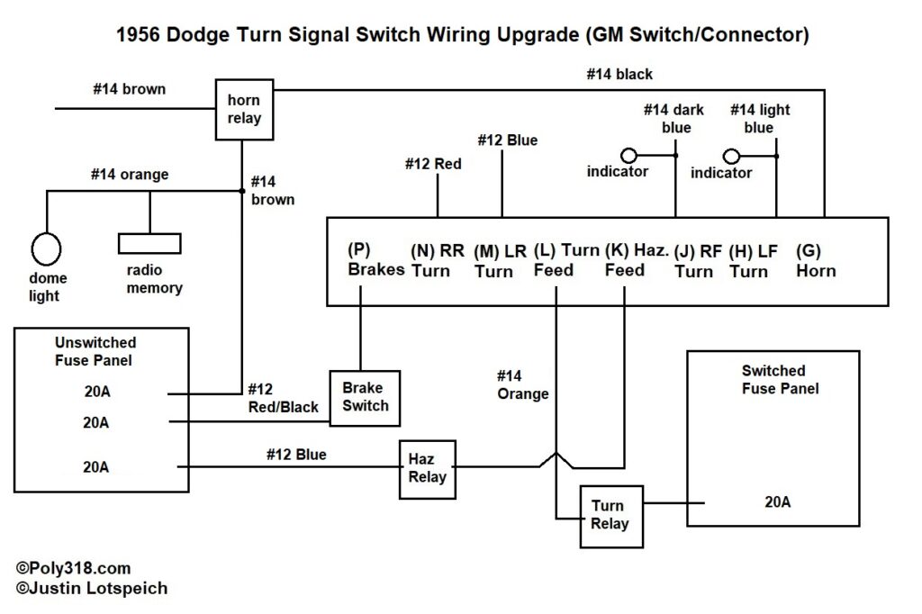
Turn Signal Switch Circuit
The turn signal circuit differs from how I would wire the factory switch because I have built my own GM steering column into the 1956 housing and am using 1970’s GM connector configuration (Figure 10). The GM turn signal switch and wiring harness do most of the work. The horn, courtesy lights (one dome and one glovebox), and radio memory share a circuit. The emergency flashers are on their own circuit. The turn signals are on their own circuit. The brake lights are on their own circuit. I’m cautious how the new pressure brake light switch will handle having four brake lights compared to two, but my research has found multiple people running four brake lights with the type of switch and no relay without overheating the switch.
Current Conclusion and Future Additions
As I progress with physically wiring the car, I will add to this article walking through steps and showing the progress. Figure 11 shows the fuse panel configuration as it stands. With the panel allowing for 12 ATO/ATC fused circuits each and the 100A alternator being 9A over what I need, I have plenty of room to add circuits as necessary, although I don’t foresee the need since the car won’t get any “luxury” items such as powered seats, windows, antennas, etc. and I hope to run a mechanical fan for the aesthetics of an early 1960’s hot rod.