Poly 318 Engine Disassembly and Machining
(applicable to 277, 301, 303, 313, 318, and 326)
Introduction
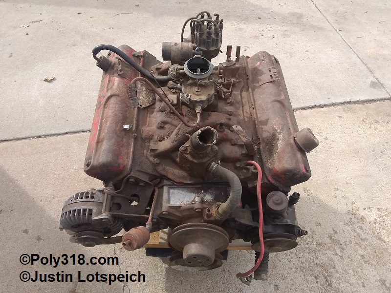
This page covers poly A-block 318 engine disassembly and machining applicable to all A-block engines and much of it applicable to LA 273, 318, 340, and 360 engines. As part of my larger engine-building series, which includes a complete engine assembly article, this technical article details how I go about tearing down a poly A-block engine, and the last section covers common machining for preparing the engine for assembly. I pair these steps with my own experience that comes from practice and industry standard procedures found in quality motors manuals that go into further detail about different clearance and measurement processes, such as properly miking cylinders. For conciseness, I leave out details on these types of steps that can be found in a quality motors manual. I have also produced a video going through the process with the written steps below.
Poly 318 Engine Disassembly
- With the engine on quality stand and a large drip pan underneath, I remove the crankshaft bolt (harmonic damper or long pulley). Note: If using a breaker bar rather than an impact gun and the engine tries to turn over, use a prybar between two flywheel/flexplate bolts to hold the crank in place.
- Remove the valve covers.
- Remove the intake manifold.
- For adjustable rocker arms, back off the adjusters, then remove the cylinder heads. For non-adjustable rocker arms, remove all head bolts except the upper center that should remain loose but threaded in. Being prepared for the head to lift off the block when removing the last bolt due to the spring tension, remove the last bolt and the head, wiggling the pushrods away from the head while lifting up.
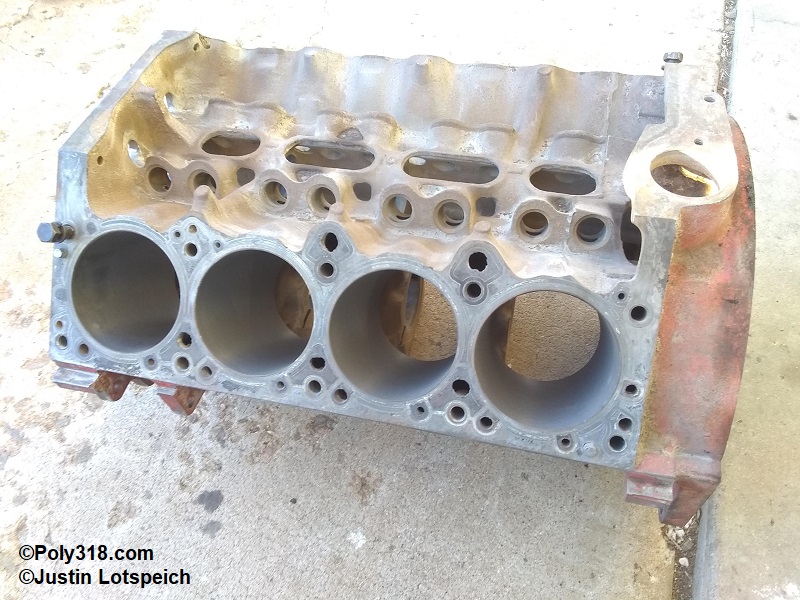
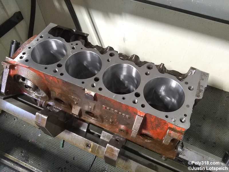
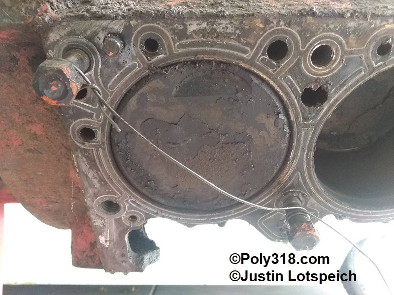
- Inspect the pistons, bores, and combustion chambers for signs of damage and corrosion. Chambers and pistons that experienced a coolant leak will often be clean of carbon buildup compared to other chambers and can include corrosion. Look for damage to cylinder walls including gouging, cracks, pitting, delamination, etc. Using a bore mike, measure the chambers to evaluate their wear and if the block can be bored to my intended purpose. If everything looks good, I continue with the disassembly; otherwise, I need to plan for replacing major components, sleeving cylinders, or finding another core.
- Remove the crank and water pump pulleys
- Harmonic Damper or Long Pulley Removal:
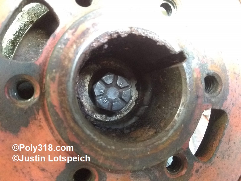
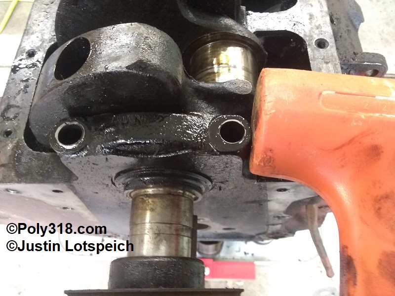
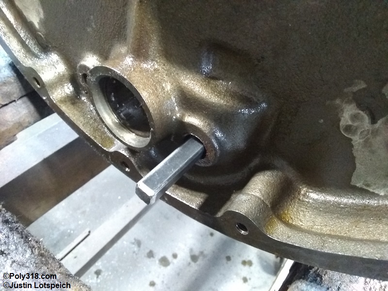
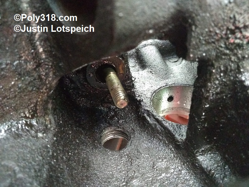
- Harmonic Damper: Insert a random 1/2″ diameter bolt into the threaded crank boss to protect the threads from the damper puller (Figure 1). Install the puller onto the damper ensuring the bolts thread through the balancer completely. Run down the puller ensuring it registers on the inserted bolt, and remove the damper.
- Long Pulley (no Damper): Using a prybar/flatbar and a rubber mallet, gently pry and tap the pulley off the crank snout. Warning: Using a puller that grips around the perimeter can bend the pulley.
- Remove water pump being careful not to twist off bolts. Some bolts go through to coolant and will likely be seized, so using penetrating oil and a back-and-forth method with a hand ratchet helps. Be prepared to have to extract or drill out a broken bolt, however. Note: prepare for coolant to spill onto the floor.
- Using a flathead screwdriver between the lifter and cam lobe, pry the lifters up. Twist out the lifters using pliers. If varnish on the lifters makes it difficult to pull them out, pry them up far enough to clear the cam lobes and then drive them down and out into the crankcase after the rotating assembly and camshaft are removed. Note: Camshafts and lifters should not be reused unless they have little miles on them. If reusing the cam and lifters, remove the lifters using fingers and a plastic pry bar and mark each lifter to its corresponding cam lobe since they are matched pairs.
- Pull the oil plug to drain the oil pan, and pull the oil filter.
- Roll the engine upside down, and remove the oil pan. Note: Prepare to catch the oil pump driveshaft located in the distributor well, although many times it will be stuck from varnish. Be prepared for any remaining coolant and oil to poor out into the drip pan.
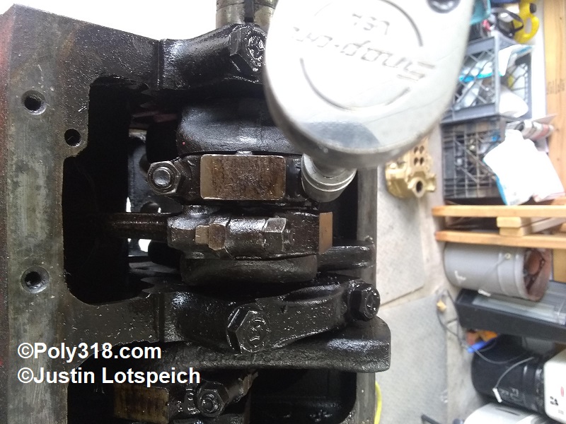
- Loosen the oil pump pickup using a pipe wrench but leave it installed. Note: be careful not to damage the pickup since it will be reused if using a stock oil pan.
- Remove the oil pump and twist off the pickup.
- If the oil-pump driveshaft is still installed, use a drift to drive out the shaft being ready to catch it. Caution: Do not damage the hex end of the shaft by excessively beating on it. If the driveshaft is extremely stuck, using penetrating oil and work the driveshaft back and forth while gently driving it out.
- Remove the timing chain cover.
- Remove the camshaft bolt, fuel-pump eccentric, and sprockets/chain prying the sprockets off the cam and crank evenly. Make sure to retain any spacer/washer between the sprocket and thrust plate if installed. Note: if the chain is tight to where the cam sprocket won’t slide off easily, ensure the crank sprocket is pried off at the same time.
- Remove the camshaft thrust plate.
- Remove the camshaft using the lifter valley casting holes to help guide it through the bearings. Note: Keep the used camshaft to either regrind, send to a grinder as a core, or to make a bearing reamer tool for new bearings that may be necessary depending on block core shift condition.
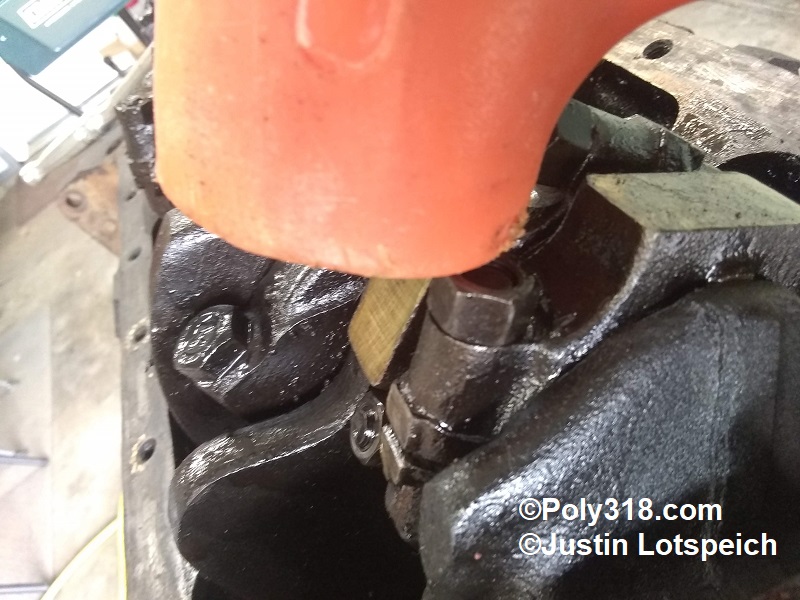
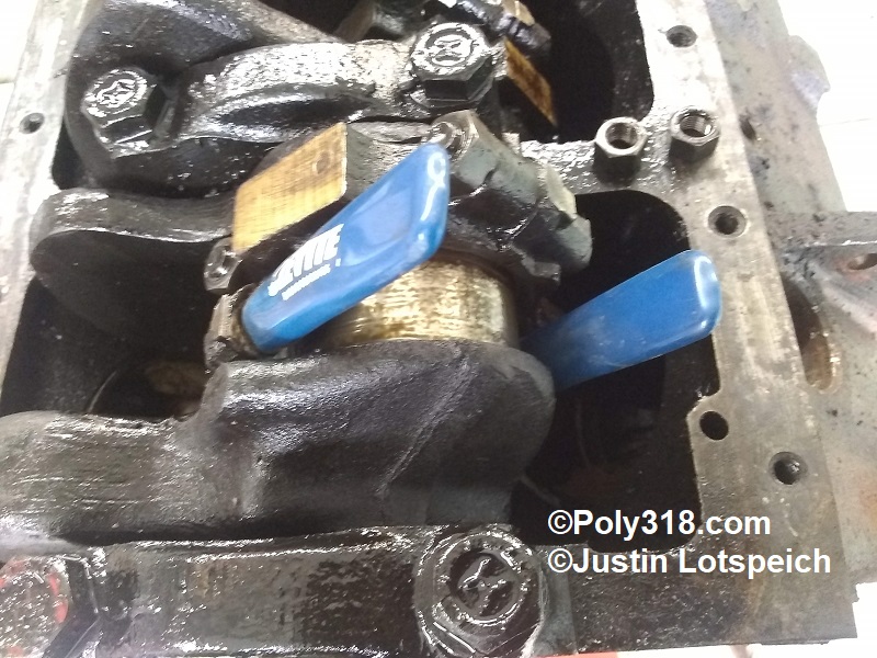
- Using a rubber mallet, temporarily tap the harmonic damper back onto the crankshaft far enough to engage the key. Gripping the damper, rotate the engine until cylinder #1’s piston is at the bottom of the bore and the rod is parallel with the bore (Figure 2). If the engine is difficult to turn over by hand on the damper, install two long bolts into the damper and use a prybar to rotate. For seized engines, see paragraph 25.1.
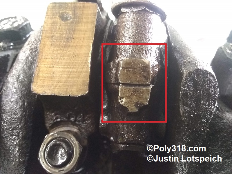
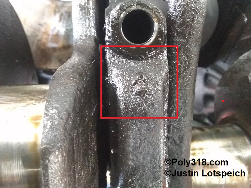
- Check the flat sides of the rod and cap to see if they are stamped with a number (Figure 3). Most factory rods and caps are numbered for the corresponding cylinder. If they are not marked, use 1/8” number dies to mark both the rod and cap sides.
- Thread into the block two short cylinder head bolts diagonal to each other, and wrap a piece of tie wire around these bolts across the piston opening giving enough slack for the piston to drop 3” before hitting the wire (Figure 4).
- Loosen #1 rod cap nuts until 1/3 is sticking up (Figure 5).
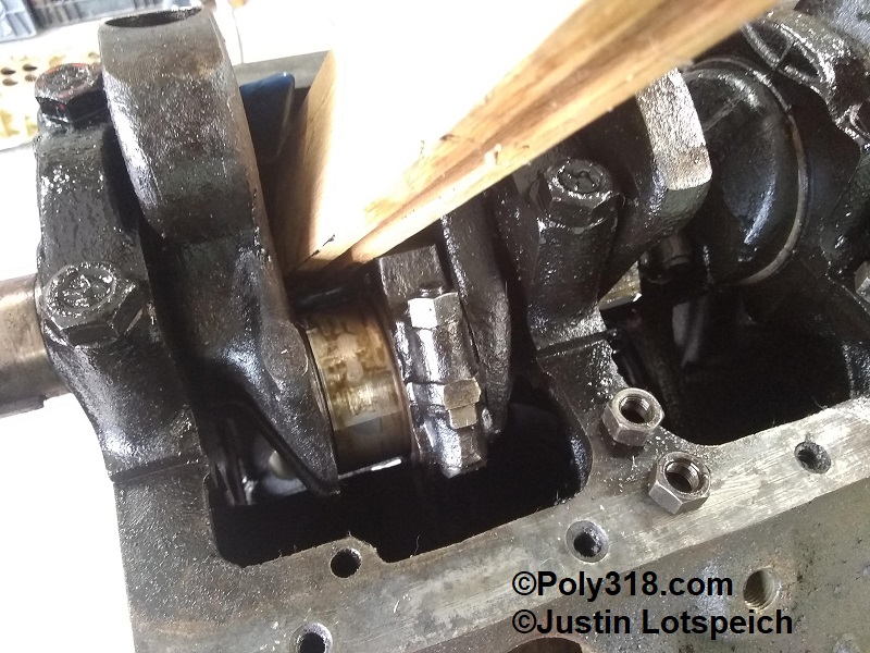
- Using a rubber mallet, hit the nut sharply to separate the cap from the rod. Don’t be scared to use some force if necessary (Figure 6). Note: In cases where the bolts drive out, use a long piece of wood to hit the bottom of the piston.
- Remove the nuts and rod cap. Note: Removing the bearing from the rod cap can show markings on the back including any bearing date and sizing details.
- Install protective sleeves over the rod bolts to protect the crank journal (Figure 7). Using a piece of wood placed against the end of the rod where the cap connects, tap the piston assembly down away from the journal. Once the rod bolts clear the crank journal, rotate the crank out of the way to where you can place a wood block onto the rod bearing. Drive out the piston assembly until the oil ring clears the block (Figure 8). Install the rod cap and nuts. Note: If the cylinder has a large wear ridge, a lot of force may be needed to using a heavy hammer against the wood block to drive out the pistons, but the wire will catch the piston. Proceed in removing the remaining piston assemblies starting next with #2 and working back.
- Seized Rotating Assemblies: Seized assemblies are a pain and take patience and time. The process depends on if you are keeping the pistons, rods, and/or crank. First, soak the front and back of the bores with penetrating oil, and use a 2×4 or 4×4 wood block and heavy hammer to beat the piston faces to free the rings. Having someone apply torque using a bar on two flywheel or damper bolts while you beat the pistons can help. If the assembly remains seized, it will need to come apart as much as possible to relieve friction. Assuming you are keeping the crank and rods, only use wood blocks/dowels to beat against the pistons/rods. Working on one hole at a time, remove the rod cap and knock out the rod bolts with a drift to remove the cap and provide clearance. Depending on where the crank throw rests, you may need to cut off rod bolts that run into the block to provide enough room for the rod to clear the journal. Be extremely careful not to mar the crank journals. Using a long wood block/dowel, beat the back of the piston until the rod drops enough to place the block on the rod to finish driving out the rod. Use caution to not beat/jamb the rod against the bottom of the bore, which can chip/crack. After each piston is removed, attempt to rotate the crank until it frees. If the crank remains seized after all possible pistons are removed no matter how much you soak the bores and beat on the pistons, the next step is drastic. One option is to cut through the rods with a cut-off wheel or oxy-acetylene torch in order to remove the crank before beating out the rest of the rod/piston; obviously, this method sacrifices the rod(s). Another option to save the rods is to use a pipe or piece of 3/4″ rebar and heavy hammer to shatter through the piston from the backside and then the frontside being careful to not contact the bore sidewall. Once the piston face is broken all the way around, the rod will be free, and the crank will likely rotate where you can remove the rod. In extremely severe seized cases where no pistons can be removed without shattering the pistons or cutting the rods, another block should be used since the bores are likely extremely corroded and will likely require expensive sleeving. For rare blocks such as a 426 Street Hemi, sleeving is worth the money, but A-blocks are plentiful enough to not justify multiple sleeves or the time and effort it take to break out every piston.
- Tap off and remove the damper.
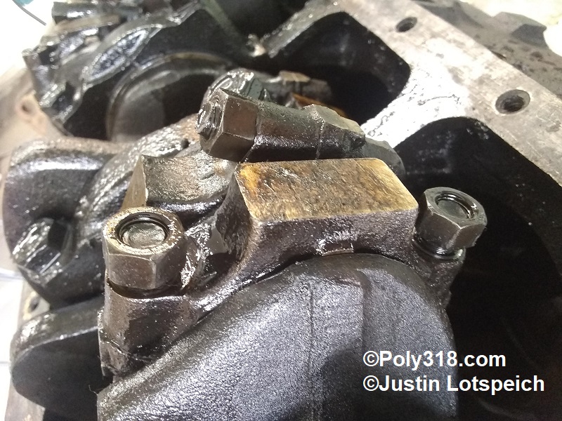
- Inspect the main caps for numbers. The factory cast numbers into the caps on the left side starting at the front as #1 and working to the rear (Figure 9). If the caps do not have legible numbers, use a 1/8” number die to mark the caps on the left side starting from the front and working to the rear.
- Remove the cap bolts. Using a rubber mallet, wrap the side of the caps to lift them. Remove the caps. The rear main cap requires wrapping on both sides back and forth to lift it off the oil pump driveshaft sleeve. Note: Removing the bearing from cap can show markings on the back including any bearing date sizing details.
- Holding the crankshaft at the rear flange and front snout, lift evenly and directly up to remove the crankshaft.
- Using a propane or oxy-acetylene torch, heat up the coolant plugs along the oil-pan rail. While hot, spray the plug threads with penetrating oil. Using a snug 6-point socket, remove the plugs. If they are not heavily corroded, place them with the rest of the fasteners; if they are corroded or have damaged threads/heads, replace them.
- Using a propane or oxy-acetylene torch, heat up the four oil gallery plugs located at the oil filter, back of the block, and left lifter gallery inner plug, apply penetrating oil, and remove. Most factory plugs take a 5/16” square socket and will be very tight. If the plugs are in good condition, save them for reuse, or replace with new hex-head plugs. Note: The large plug adjacent the cam bore does not block an oil gallery, but gunk often gets trapped around this plug that the hot tank does not always remove, so it is wise to remove the plug. The three other oil-gallery plugs should always be removed in order to use rifle brushes to properly clean out the galleries. Don’t forget to remove the inner plug for the lifter gallery so that a rifle brush may be run completely through (Figure 11).
- Insert a long pipe or other object through the camshaft bore and knock out the rear camshaft plug. Save the plug for reuse.
- Roll the engine so that the side is horizontal, and remove the oil filter stud and plate. Note: The plate will be stuck well, so use a drift/screwdriver through the holes to pry it loose.
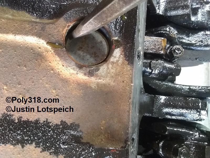
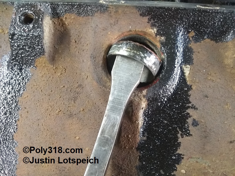
- Use a cold chisel down in the cup to drive one side of the freeze plug down until it drops into the jacket and the other side comes up (Figure 12). Using a prybar or vice grips, pry the freeze plug up through the hole (Figure 13). If the plug falls into the jacket, fish it out and repeat. Both front plugs and the right rear are difficult to remove this way because there is not enough room for them to drop down far enough to tilt sideways. I have the best luck drilling a #12 self-tapping sheet metal screw through the cup base near the wall and using a flat bar or claw hammer to pop them out. If they are so tight that the screw strips out, these plugs require driving into the jacket and prying the sides in until the plug collapses/distorts enough to be removed. Be careful not to beat these plugs down hard against the cylinder bore with a hammer since it can crack the casting.
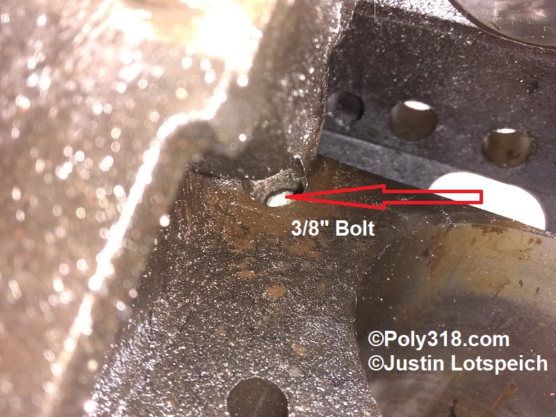
- With the engine upside down, drop a 3/8” bolt into the distributor bushing (Figures 14 and 15). Using a long drift, bolt, or piece of all-thread, drive down onto the bolt to press out the bushing.
The block disassembly is complete. I cover machining at the end of the page after the following disassembly figures. Cylinder head disassembly is detailed in another article.
Disassembly Figures
Poly 318 Engine Machining
The first step in machining is cleaning the engine and components using a combination of hot tanking with caustic solution, scrubbing the outside with a brush and cleaning all oil galleries with riffle brushes, pressure washing the oil galleries and nooks, and sandblasting where necessary.
Once the initial cleaning, we used magnetic particle inspection (aka magnaflux) to check 1/4″ of the exterior inward of the block and cylinder heads for cracks/defects. There are a few different forms of magnetic particle inspection, and I was lucky enough to have access to some high-end equipment. I summarize here leaving out the finer details, and the process we used consists of connecting the part to the magnetizing unit, coating the part in a fluorescent iron-powder solution, magnetizing the part, inspecting it under black light, re-magnetizing it in a different current direction, inspecting it again, and demagnetizing the part when finished. The iron powder in the solution gravitates toward the magnetic fields created by anomalies in the surface including tooling marks, casting marks/flash, sharp edges, cracks, etc. The condensed solution in these areas creates a lit area under black light that I marked with soap stone for additional close inspection when I couldn’t clearly tell that the anomaly wasn’t damage. We checked the block, main caps, cylinder heads, cast-iron timing cover, and intake manifold and found no issues. I had large gloves on covered in the fluorescent iron-powder solution, so no photos for this process.
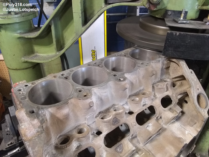
I wasn’t able to work at the machine shop the day we planned on beginning machine work, so my machinist overbored the block to 0.025″ in order to see if it would clean up for 0.030″ over pistons before I special ordered them. The bores cleaned up nicely aside from a light mark at the ridge line that would clean up during final honing (Figure 1a). The same day, my machinist cut the larger 2.02″ intake valve seats, cut and inserted the larger 1.675″ hardened exhaust seats, and drilled out and pressed in new iron valve guides for 11/32″ valve stems. See the article on the porting work I did on the heads that shows the larger valves.
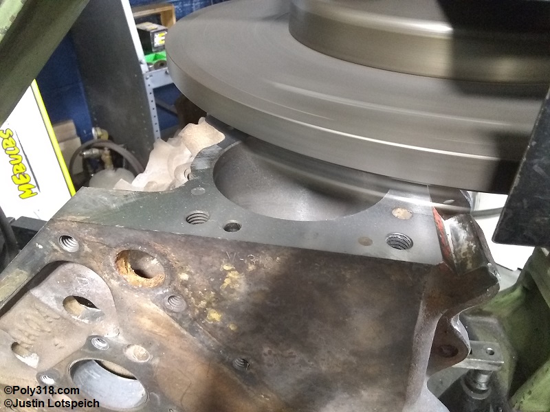
I returned to the shop to tackle milling the block deck in order to measure final block deck before I could order the custom forged dome pistons. I used a trusty Storm-Vulcan Block Master 85b, and I was impressed with the block compared to many contemporary blocks. Once I jigged up the block for the left (driver) bank and took some initial passes to determine how far out the deck was, I concluded that the front at cylinder #1 was 0.005″ higher than the rear at cylinder #7 in relationship to the crankshaft. I made a 0.004″ pass across the deck (Figure 1b). After inspecting the surface, I decided to make a final 0.003″ pass for a total of 0.008″ off the left bank (Figure 1c). I rolled the block to work on the right (passenger) bank, and after making an initial light pass concluded the front of the deck at cylinder #2 was 0.003″ higher than the rear at cylinder #8. To square up the right bank even with the left, I made two 0.004″ passes for a total of 0.008″ off the right deck. It isn’t uncommon to have to take 0.020″ off a small block Chevrolet deck to get things squared up even with the crankshaft, so I was happy with the lack of core shift and unevenness in this A-block since 0.008″ is nothing in the scheme of things. I miked the deck height at 9.588″, which was the last measurement I needed to order the pistons to place them at zero-deck.
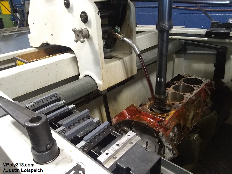
Fast forward sixteen weeks until I received the pistons and rings, I returned to the shop to tackle the final machining of the block. After I miked the pistons to confirm their diameter and after reviewing the specifications for the Hastings moly 1/16″ x 1/16″ x 3/16″ rings that call for a 600-grit finish, I settled on 0.005″ clearance and a two-step “plateau” cross-hatch honing using a Sunnen CV616. The Plateau process starts with a 300-grit stone down one bank, switching stones to 600, and finishing the bank with the 600-grit stone. This process provides a dual-grit pattern to assist with ring seating since the lower chrome rings like a coarser hatch while the moly rings like a finer hatch. While I prefer to use a torque plate, my machinist couldn’t find his LA/Magnum torque plate after a recent shop remodel, I couldn’t locate one to borrow from the three other local machine shops who know and trust my machinist, and I didn’t want to spend $350 to buy one. If this were a 550 HP build, I would have purchased a torque plate, but I settled on an old-school plate-less hone. Between the 300-grit pass and the final 600-grit pass, I chamfered the top of the bores. Figures 1d and 1e show honing and the finished block, although the nice cross-hatch doesn’t show up well in the photo. After honing, I tossed the block back into the hot tank for a semi-final wash. The final wash I do by hand using a power washer, bucket of hot water and with heavy dose of Dawn dish soap, and a variety of bore, rifle, and other brushes just before I begin assembly that I cover in my next article.