Classic Vehicle Transmission Cooler System with Integrated Spin-on Filter
Introduction
Most classic cars and trucks with automatic transmissions require a transmission fluid cooling system, and it’s extremely wise to have one even if the vehicle didn’t originally have one. Most factory system take the supply and return lines directly from the transmission ports into the radiator’s integrated transmission fluid compartment located adjacent to the lower tank. While there is some debate if this is in fact a fluid cooling system or a heating system–which largely depends on the ambient temperature–the fluid is cooled at any temperature above the engine coolant’s temperature down to approximately the engine’s temperature, but on a properly built system the fluid is cooled well below the engine temperature under average driving conditions. For healthy factory engine and transmission cooling systems, the factory transmission cooling system works well. For builds with high-stall torque converters, that will see racing, or that will see heavy towing which all increase fluid temperatures, an external transmission cooler provides better protection since the transmission cooler is not dependent on the engine’s coolant temperature. This article covers designing and fabricating a transmission cooling system that includes a spin-on filter for added protection beyond the transmission’s pan filter.
Normal and Optimal Transmission Fluid Temperatures
The engine coolant on most healthy classic vehicles at normal sustained operating temperature ranges from about 150°F – 205°F with around 180° ideal, depending on multiple variables. I discuss in great detail the cooling system, thermostat, and thermostat selection in another article. Fluid that reaches 200°F average in the pan is still within a safe range for the hottest fluid coming out of the pump but will see the fluid degrade quicker than lower temperatures. Fluid reaching above 200°F average in the pan directly correlates to damaging the fluid and decreasing its life at an exponential rate. By 240°F, the fluid begins rapidly deteriorating due to overheating. For builds that reach fluid temperatures above 180°F using a factory radiator cooler, an external air-cooled cooler is a wise modification.
External Transmission Fluid Air Cooler
Keep in mind that the external air cooler should be sized correctly since one too small will not keep the fluid below 180°F, and one too large will super-cool the fluid below the 150°F minimum required by most transmissions used in classic vehicles for optimal transmission functionality.
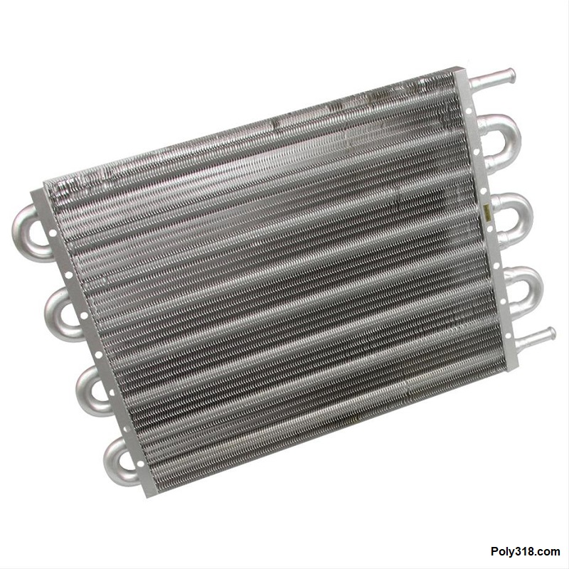
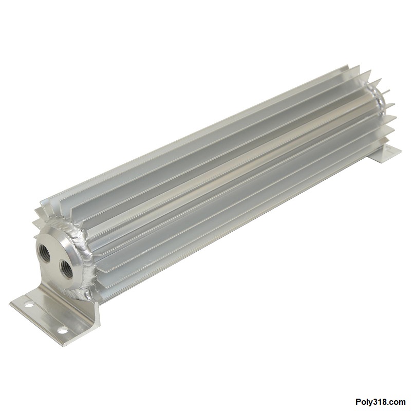
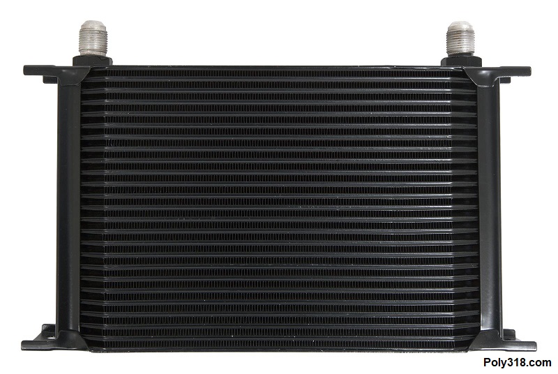
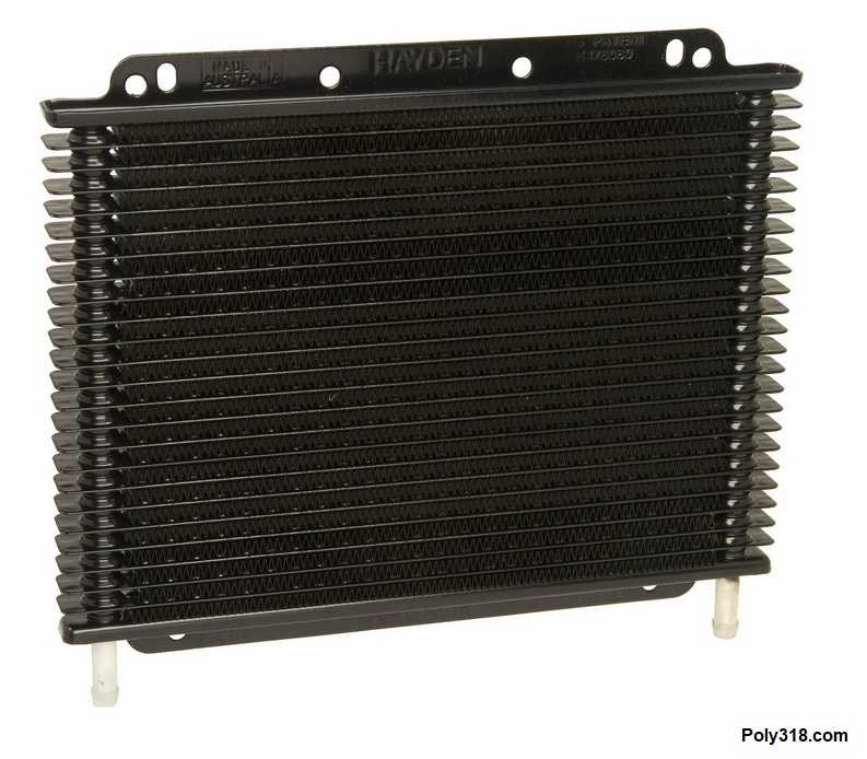
There are different external cooler designs that have different efficiency, structural strength, and purpose including tube-and-fin (Figure 1a), compact heat-sink (Figure 1b), and plate-and-fin (Figure 1c). The tube-and-fin cooler is the cheapest type. It isn’t as efficient as other designs due to relying on fewer tubes, and the fins are typically thin and easily damaged. The compact heat-sink has its place, especially in systems with limited space, but they are not the most efficient since there is less surface area for cool air to pass over. The plate-and-fin design is the most efficient type of cooler since it uses many tubes (aka plates) like an engine radiator with sturdy fins. Any of these coolers may include a shrouded electric fan for installation in areas that don’t see adequate airflow, although the plate-and-fin is the most popular cooler to pair with an electric fan.
These coolers can have connections including barb, NPT bungs, and AN fittings. The cooler circuit on TorqueFlite 904 and 727 transmission is low-pressure between 30 psi at the transmission cooler supply port to 5 psi at the return port, so any of these fittings work well.
Transmission Temperature Gauge Placement
If a transmission fluid temperature gauge is desired, which isn’t a bad idea for performance and towing builds, there are four location options to install the sending unit:
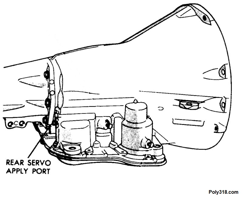
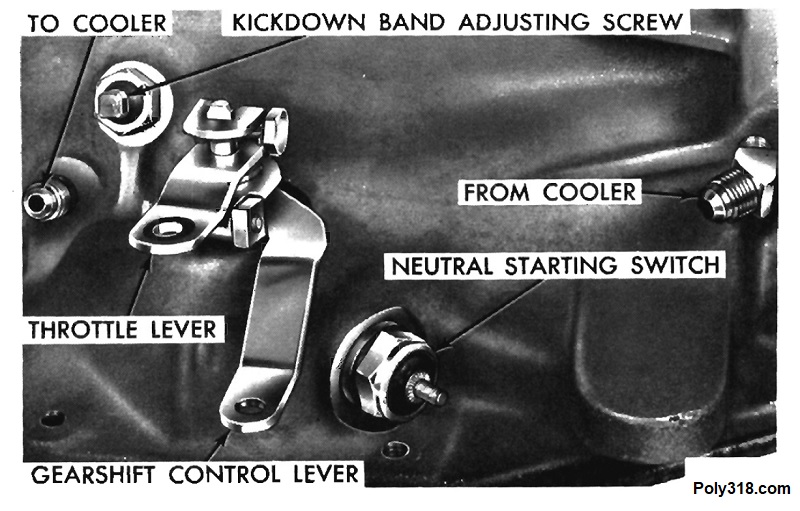
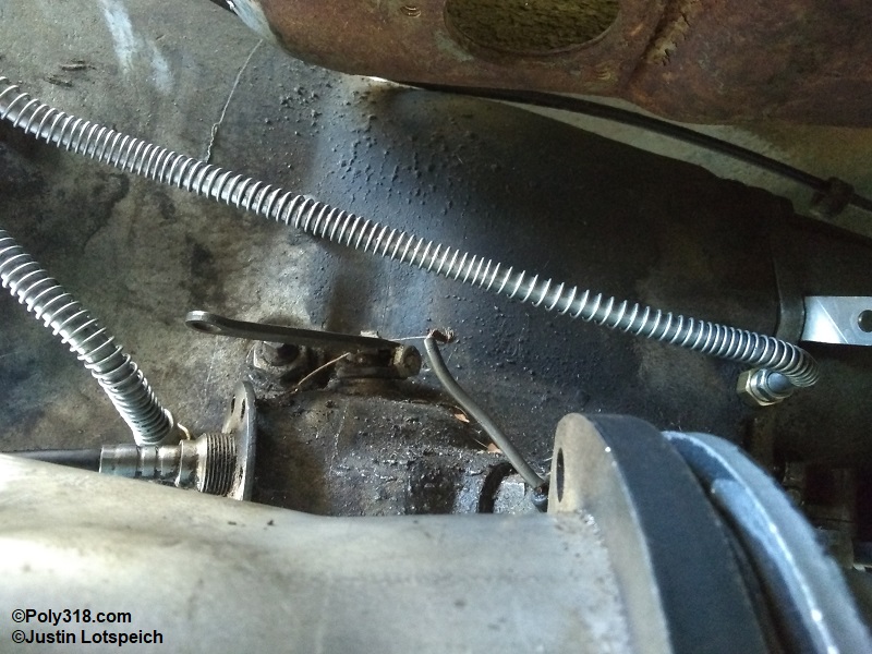
- Factory port in the transmission (Figure 2 rear servo apply port for a TorqueFlite 727): Not the most accurate average temperature but gets the job done on stock towing builds.
- Side of the transmission oil pan: The most accurate location to measure average fluid temperature.
- In the cooler supply line between the transmission cooler radiator: Measures the hottest fluid in the system aside from directly exiting the converter, which isn’t measurable.
- In the cooler return line between the cooler radiator and transmission: Measures the coldest fluid in the system.
I prefer to place the transmission temperature sending unit in the side of the oil pan to measure the average temperature since a pan temperature below 150°F or above 180°F will tell me if the cooler is too small, too large, or is placed in a location that is getting too much or too little fresh air flow. Aluminum oil pans that don’t have an NPT port for a sending unit can be drilled and tapped, and steel pans require drilling and welding in a NPT bung. The sending unit should be placed in the side of the pan for protection versus out of the bottom where it can easily be damaged.
Designing the Transmission Cooler System
I built the system I describe in this article for my 1956 Dodge coupe that is powered by a poly 390 A-block stroker backed by a push-button TorqueFlite 727 that I rebuilt with performance modifications, a custom high-stall torque converter, and a deep aluminum pan. The tight clearance between the engine cooling fan and radiator would not allow me to utilize the aftermarket aluminum radiator’s transmission cooler even if I wanted to, so I opted for an external cooler that I placed in the center lower front of the radiator. I went with a plate-and-tube radiator with 5/16″ (actually 11/32″) barb fittings. I purchased a Hayden model 678 radiator that measures 9.5″ high x 11″ long x 0.75″ deep and includes the attaching hardware and a length of 11/32 cooler hose (Figure 3a). This Hayden cooler is made in Australia and is excellent quality, which is necessary when the cooler is mounted in front of the radiator where it will take abuse from inspects and other road debris.
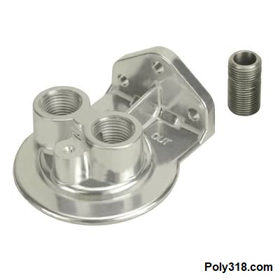
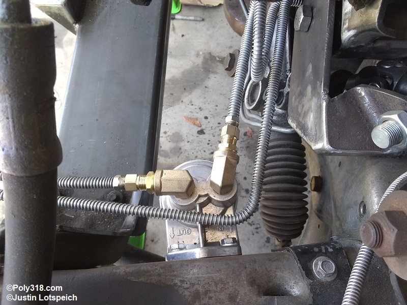
Since I am designing the system from scratch, I built in a spin-on filter that greatly increases filtration and protection. The spin-on filter also captures debris in the fluid after it passes through the transmission pressure circuits and before they land back in the pan, both decreasing the debris the pan filter must capture and letting me swap in a new spin-on filter after the rebuilt transmission has been in service for 100 miles to remove the typically higher amount of debris after a rebuild. Even though I was using 5/16″ lines that would make 1/4″ NPT appropriate, I used a Derale adapter 25005 with 3/8″ NPT ports (Figure 3b) because I was concerned that the 1/4″ NPT to 1/2″-20 double inverted flare 90° street elbow coming out of a 1/4″ NPT filter adapter would be a weak point since the supply line would be prone to tugging that fitting sideways when the engine rolls under acceleration. 3/8″ NPT elbows would be much stronger, although the aesthetics aren’t as clean as a 1/4″ 90°. I designed the connections to go from a 3/8″ NPT street elbow, reduce to 1/4″ NPT, followed by 1/4″ NPT to 1/2″-20 double inverted flare adapters since I couldn’t find a company that makes a 3/8″ NPT male to 1/2″-20 double inverted flare street elbow in any fittings catalog.
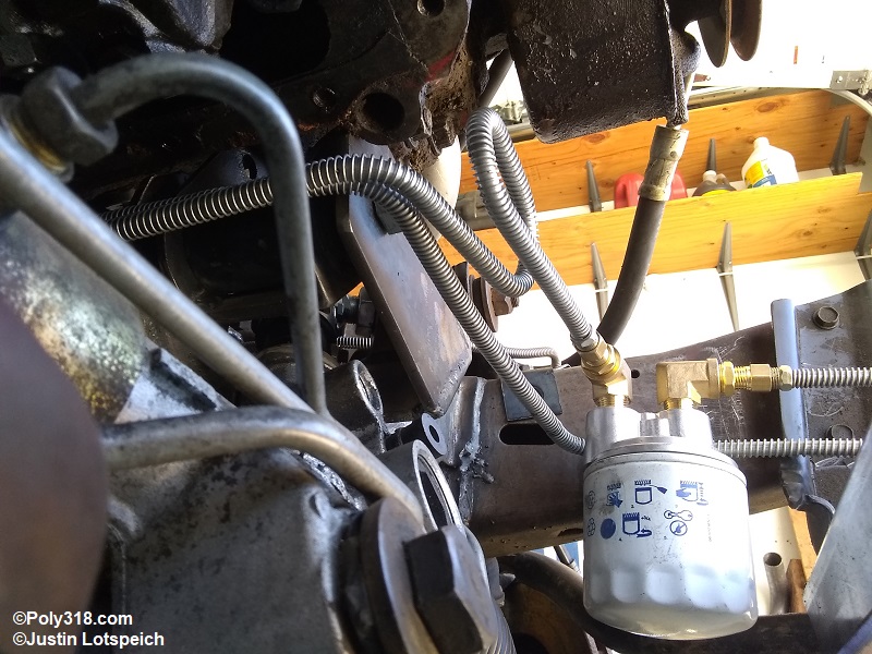
After digging through the Wix filter catalog, I landed on using a Wix 51525 designed for transmission oil with specs 3/4-16 thread, 8 – 11 psi bypass valve, 7 – 9 gallons per minute, 21 micron filtration, 3.66″ diameter x 5.2″ height, and has a rubber seal that fits the adapter. The filter doesn’t have a drain-back valve, which isn’t a problem since my design places the filter below the transmission pump to where gravity won’t allow drain-back.
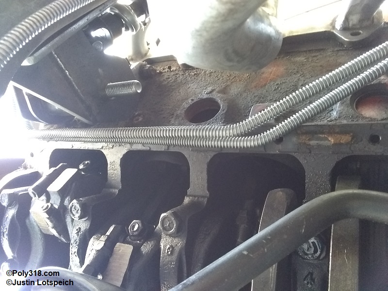
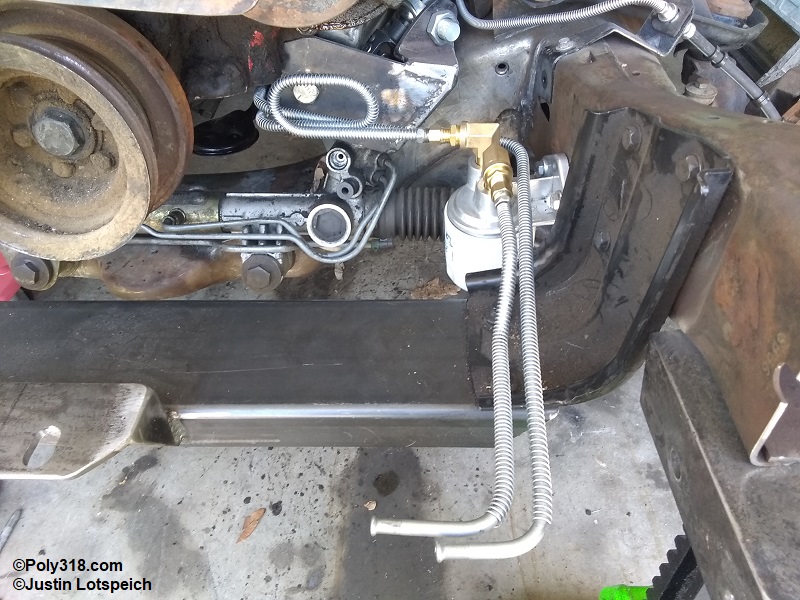
The system uses 5/16″ hard lines with double inverted flare fitting on both the supply and return lines with the only soft connections being 8″ hoses from the hard lines to the cooler since it would be impossible for me to install the lines through the valence if I ran hard lines all the way to the transmission radiator. For routing, I abandoned the factory LA-block and Magnum-block route and ran the lines from the transmission up over the starter motor, along the engine oil pan rail, over to the filter adapter mounted to the chassis under the battery tray, and forward where they turn and end underneath the front valence. The rubber hoses then curve up through a hole I cut in the valence–which won’t be seen when looking at the front of the car–and connect to the transmission radiator. This routing allows me to remove and install the lines from underneath the car with only needing to drops the starter motor, and it allows me to remove/install the starter motor without disconnecting the cooler lines. The route is also inconspicuous, making it aesthetically appealing when looking into the engine bay.
Transmission Cooler System Fabrication
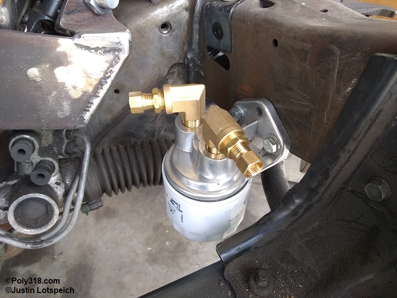
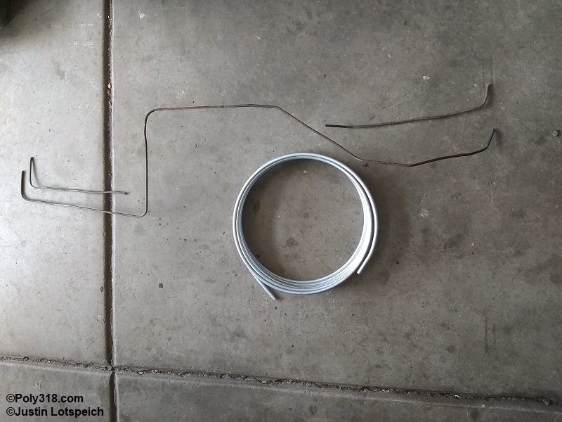
After sketching out the routing plan and necessary fittings on paper and analyzing the plan on the car, I positioned the filter adapter and drilled and tapped two holes into the inner frame rail to secure the adapter with 1/4″ bolts, and I mocked up the fittings to convert from 3/8″ NPT to 1/2″ female double inverted flare (Figure 4a).
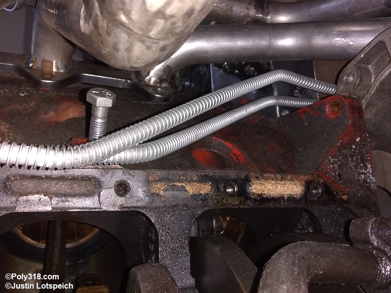
Figure 4b shows the supply and return ports on a TorqueFlite 727 and 904. I began building the templates with the return line from the transmission forward by bending up a scrap piece of 3/16″ brake line that I tore out of the car when fabricating a new brake system, although I have used rebar tie wire in the past. I then bent up the supply line pieces that differ from the return line’s routing (Figure 4c). Once I was satisfied with the routing, I began bending the new 5/16″ zinc-plated steel lines. I placed a loop in the supply line adjacent to the filter since this point in the system will have the most flex as the engine rolls under acceleration and the filter adapter remains fixed on the chassis. The captured LA motor mounts I’m using greatly limit the engine roll compared to the earlier un-captured mounts, but there is still a very small roll to the engine. The loop, using the same principle as a brake system, allows more give in the line without leading to cracks from work hardening. From the filter, a short piece of line runs to the transmission radiator inlet. The return line shares almost the same route aside from continuing around the filter. After I mocked up the lines and adjusted the bends, I installed 1/2″-20 male flare nuts on the transmission ends and flared the tubing to double-inverted flare. I slid on 5/16″ stainless steel coil gravel guard since the lines run around moving parts and are more susceptible to rubbing damage. The filter outlet connection also received a 1/2″-20 male flare nut, a double-inverted flare, and gravel guard. I flared the cooler connections with a bubble flare that accepts the 11/32″ cooler hose and a hose clamp. For directions on flaring brake, fuel, and transmission cooler hard line, see my article on building the fuel system. Figures 4d – 4i show the finished hard lines, although the photos don’t show the clamps I fabricated to hold the lines along the oil pan rail and at the valence.
I placed the transmission radiator at the center of the engine radiator and resting on the bottom lip of the tank with a piece of 1/4″ foam insulation between the transmission radiator and the tank to stop direct rubbing and wear. I used the included plastic ties to secure the transmission radiator to the engine radiator at each corner (Figure 4j). From the fittings, I curved the 11/32″ hoses down through the valence to the supply and return lines securing them with hose clamps (Figure 4k).
Conclusion
The transmission cooling system I designed and fabricated makes use of a route that allows me to remove and install the lines and the starter motor with ease, uses a spin-on filter for added protection, and a plate-and-fin cooler to keep the fluid below 180°F on even the hottest of days and hardest of loads on the transmission–and we get plenty of hot days in our Colorado summers and plenty of load at the drag strip and climbing in the Rocky Mountains. This system could be simplified by deleting the spin-on filter, but the extra work and parts it takes to install the filter are well worth the benefits to the transmission. While different vehicles will require different routing, lines sizes, etc., I hope this article provides an example of one system that may be applied to other builds.