Poly 318 Valve Lash
and Preload Adjustment
(applicable to 277, 301, 303, 313, 318, and 326)
Introduction
As part of my larger engine-building series, I detail the process for adjusting valves. When people say adjust valve “lash,” they refer to the amount of clearance between the rocker arm tip and the valve stem tip. Zero lash means no clearance, 0.013” lash means a gap of 0.013.” Preload refers to the additional pressure placed on the pushrod/valve after reaching zero lash. Think of preload like a clock with the wrench as the hand. Zero lash is the wrench at 12:00, 1/2 turn preload is 6:00, and 3/4 turn is 9:00. A-block solid lifters should never have preload since there is no spring in the lifter to adsorb the preload; A-block hydraulic lifters should always have preload for the system to function properly.
One may have come across a manual, forum post, or YouTube saying to adjust valves while running, but it is not necessary, is less accurate, and is far more cumbersome in process and cleanup than adjusting the valves with the engine off. Adjusting with the engine running depends solely on the mechanic’s sense of sound, which is very subjective depending on the person’s quality of hearing and all the other background noises involved (engine, fan, hissing carburetor venturies, exhaust, etc.). Adjusting lash with the engine off uses quantitative, proven measuring tools and the mechanic’s more-precise sense of feeling with fingers, and it allows the mechanic to take time and not rush the process.
Another area worth discussing is the sequence. Some people adjust valves one cylinder at a time, others all intake and then all exhaust following the firing order, and others follow a complex process that goes #1 intake open, adjust #6 intake, #8 intake open, adjust # 5 intake, etc. For people with no experience adjusting valves, it is best to stick with the one cylinder at a time approach even though it will take longer. For those comfortable with adjusting valves, the firing order method of adjusting all intake and then all exhaust is quicker, allowing the engine parts to stay warmer and closer in temperature while adjusting. I do not at all recommend the “when #1 intake is open adjust #6 intake” method since it is no faster than the firing order method and ads an unnecessary layer of complexity. I provide the firing-order all intake, then all exhaust method, but the same exhaust and intake valve position applies to the one cylinder at a time approach.
A-block Lash/Preload
Note: Always confirm lash/preload specifications with the camshaft manufacturer. See the specification page for complete engine details.
Hot Solid Lifter Lash
- Intake: 0.013”
- Exhaust: 0.021”
Cold Solid Lifter Lash Add 0.002” to hot lash (for rebuild setup only)
- Intake: 0.015”
- Exhaust: 0.023”
- Note: cold valve lash should be checked/adjusted hot after cam break-in.
Hydraulic Lifter Preload (both intake and exhaust)
- Hot: 3/4 turn after zero lash
- Cold (for rebuild setup only): 1/2 turn after zero lash
- Note: cold valve preload should be checked/adjusted hot after cam break-in.
Solid Lifter Adjustment (with adjustable rocker arms)
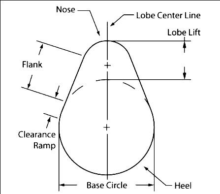
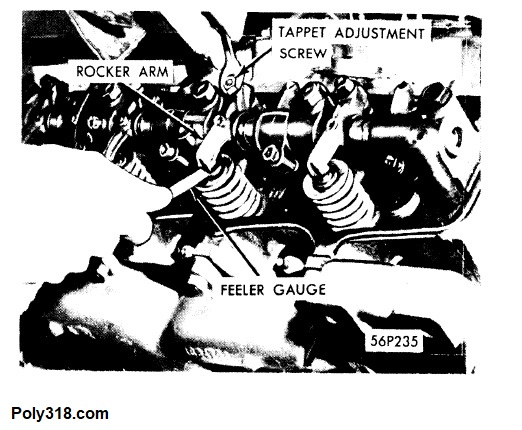
Before getting to the steps, I want to clarify the minute details of measuring lash: I will have the exact feeler gauge and a feeler gauge the next size up, such as a .013” exact and .014” next size (I cannot simply add a 0.001 gauge since it will fold when trying to insert it). Once the lifter is on the very bottom of the heel of the cam lobe (Figure 1) and the adjuster is backed off slightly, I slide the exact gauge between the rocker arm and the valve stem tips and slowly tighten the adjuster while moving the gauge back and forth until I feel slight resistance (Figure 2). For roller rocker arms, move the gauge side to side. Using my thumb and index finger, I jostle the pushrod side to side to ensure it is centered in the lifter and check to see I still have the same drag on the gauge. I switch to the larger gauge and try to slide it between the rocker arm and valve stem tips. If I cannot, the lash is properly set. If I can slide in the larger gauge, I go back and tighten the adjuster until the exact gauge slides in but the larger gauge does not. This process is more precise and quicker than only using the exact gauge and trying to feel the proper amount of drag.
- Warm up the engine to running temperature and shut off.
- Unplug the distributor coil wire for safety.
- Remove both valve covers.
- The A-block firing order is 18436572. Using a bump-starter (one can use a ratchet on the crankshaft bolt instead), I rotate the engine until I see cylinder #1 exhaust valve just start to open. Adjust the INTAKE valve for #1. If using a jam nut, tighten it using a closed-end wrench making sure to hold the adjuster in place with another wrench (usually an Allen). If rotating the crank by hand is difficult, like on an engine with high compression, loosen the spark plugs first.
- Now I rotate the engine until cylinder #8 (the next in the firing order) exhaust valve just starts to open. Adjust the INTAKE valve for #8. Continue this process for cylinders 436572.
- Once all the intake valves are adjusted, I move onto the exhaust valves, which is a similar procedure but with a crucially different step. I rotate the engine until I see cylinder #1 intake valve reach maximum lift (the valve is completely open) and then rotate the engine just until the intake begins to close. Adjust the EXHAUST valve for #1. Continue this process for cylinders 8436572.
- After all intake and exhaust valves are adjusted, confirm jam nuts (if equipped) are secured and that no debris or tools are left on the heads, and replace the valve covers.
Hydraulic Lifter Preload (with adjustable rocker arms)
Before getting to the steps, I want to clarify the minute details of setting preload: once the lifter is on the very bottom of the heel of the cam lobe (Figure 1) and the adjuster is backed off slightly, I grip the pushrod between my thumb and index finger. Rotating the pushrod back and forth, I slowly tighten the adjuster until I feel very slight drag on the pushrod. Using my thumb and index finger, I jostle the pushrod side to side to ensure it is centered in the lifter, then spin again to make sure I still feel the same drag. If I am uncertain, simply back off the adjuster and repeat. Once I confirm slight drag in the pushrod, the valve is at zero lash and ready to set preload. Placing a closed-end wrench on the adjust to where it looks like a clock hand at 12:00, 3:00, 6:00, or 9:00 depending on wrench clearance. Turn the wrench 1/2 turn for cold rebuilt engines (so from 12:00 to 6:00) or 3/4 turn for hot engines (so from 12:00 to 9:00). Tighten the jam nut if equipped.
- Warm up the engine to running temperature and shut off.
- Unplug the distributor coil wire for safety.
- Remove both valve covers.
- The A-block firing order is 18436572. Using a bump-starter (one can use a ratchet on the crankshaft bolt instead), I rotate the engine until I see cylinder #1 exhaust valve just start to open. Adjust the INTAKE valve for #1. If using a jam nut, tighten it using a closed-end wrench making sure to hold the adjuster in place with another wrench (usually an Allen). If rotating the crank by hand is difficult, like on an engine with high compression, loosen the spark plugs first.
- Now I rotate the engine until cylinder #8 (the next in the firing order) exhaust valve just starts to open. Adjust the INTAKE valve for #8. Continue this process for cylinders 436572.
- Once all the intake valves are adjusted, I move onto the exhaust valves, which is a similar procedure but with a crucially different step. I rotate the engine until I see cylinder #1 intake valve reach maximum lift (the valve is completely open) and then rotate the engine just until the intake begins to close. Adjust the EXHAUST valve for #1. Continue this process for cylinders 8436572.
- After all intake and exhaust valves are adjusted, confirm jam nuts (if equipped) are secured and that no debris or tools are left on the heads, and replace the valve covers.
Hydraulic Lifters (with non-adjustable rocker arms)
The factory parts are made to put preload into the system. There is no preload adjustment possible aside from replacing worn valvetrain or changing the pushrod length. Replacing rocker arms with adjustable rocker arms like those used on solid lifter A-blocks is an upgrade and should be considered for any A-block, especially performance builds, to set consistent preload.
Figures