1956 Dodge Coupe
Ford 8.8 Rear End Swap
and
Spring Perch Welding
(applicable to 1955 – 1956 Dodge and Plymouth)
Introduction
While building the poly 390 stroker and push-button 727 TorqueFlite are two things, planting the power is yet another, especially for a car that is going to see 1/4-mile passes on sticky cheater slicks. As with the factory front suspension with a stock 190 HP Dodge poly 270 engine and PowerFlite two-speed transmission, there is nothing inherently unsafe about the factory rear axle, but there are severe weaknesses, antiquated design features, and parts are more difficult to find and more expensive than more modern axle assemblies. Rather than spending time discussing all the issues with running the factory rear end or a 1956 Chrysler/Desoto rear end, I’ll just say it’s not an option. To start the debate for a swap, the 1956 Dodge and Plymouth have a 60″ axle width drum-to-drum with 41″ spring perch centers. The spring perches aren’t much of an issue for me since I can weld on new ones, but shortening the axle is something I prefer to not have to do.
A popular swap for a 1956 Dodge and Plymouth that will see track time putting out up to 600 TQ is a 1965 – 1970 B-body 8.75″ (pre-1965 have tapered axles). While once a cheap and easy option, those days are long gone despite what some say online. I run across the occasional forum post where someone asks for budget rear end swaps and someone replies claiming they purchased a complete, working posi 8.75″ for $400, but those steals are very few and far between if they are even true as of 2022. From all the swap meets and online ads within 200 miles of my house that I have scoured over the last five years, a complete posi 1965 – 1970 8.75″ assembly core that needs rebuilding costs between $800 – $1,000 and almost always have the smaller 741 carrier and gears taller than 3.55. The core will also need new forged axles for my purpose. By the time I buy such a core, purchase a ring and pinion and install kit, purchase forged axles, and go through the unit including bearings and brakes, I’ll be into an 8.75″ $2,000 if not more.
Another option is a new Ford 9″ built to whatever width I want. Speedway Motors either manufacturers or carries everything needed to build a Ford 9″ with a new housing, new 3.70 posi third member, and new forged 31-spline axles. Factory 9″ drum brakes can be bolted on, or Ford Explorer 8.8″ disc brakes can be adapted. Here again, similar to the 8.75″, this Ford 9″ assembly and after locating and rebuilding brakes will run about $2,700 after shipping and tax.
8.8″ Ford Explorer Options
Now for where I have settled on the matter: 1990 – 2001 Ford Explorers use a strong 8.8″ rear axle that measures 59 -1/2″ drum to drum with a 38-1/2″ spring perch center. It also has an offset pinion like the 1956, so driveshaft to tunnel clearance will not be an issue. In multiple tests, the Explorer 8.8″ is comparable in strength to the Mopar 8.75″ and weighs about the same. The Mustang and Ranger also used a version of the 8.8″, but the Explorer has some benefits over the others. All Explorer 8.8″ assemblies feature a heavy gauge 3.25″ diameter housing, thick cast center section, forged 1.31″ diameter 31-spline axles, pinion flange for a bolt-on yoke, and 5 on 4-1/2″ bolt pattern. 1990 – 1994 have 10″ drum brakes like the Ranger and Mustang versions, whereas 1995 – 2001 have 11″ disc brakes and a slick cable-operated emergency brake setup with brake shoes that use the inside of the rotor as a drum. While many came with open differentials, many–particularly the Sport/Sport Trak models and those with tow packages–came with 3.27 (door label code D1), 3.55 (code D5), 3.73 (code D4), or 4.10 (code D2) posi differentials. Unless removed, there will also be a tag on one of the cover bolts with the ratio and L/S (limited slip). Salvage yards are ripe with the correct years, and complete units are under $200. Parts are cheap and readily available at any parts house. The downsides of the 8.8″ are that they use the axle shaft as the roller bearing inner race and don’t have a drop-out differential, but these are not critical for my build since the bearing design is strong/dependable, I don’t plan on swapping gear ratios, and I don’t mind the extra hassle if I have to change ratios. With the strength, gearing I want (3.73:1 posi), disc brakes with easy emergency brake hookup, almost exact width, and under $200 price tag, the Ford 8.8″ is an excellent choice for our 1956 Dodge.
Pulling the Ford 8.8″ Rear End
I showed up to the same salvage yard where I picked the 1996 Dodge Dakota front clip after watching their online inventory until they had a handful of 1995 – 2001 Explorers in stock. Showing up to the first car, I found a 2001 wrecked on the front side and 160K miles on the odometer. I was pleased to find the D4 door label code I sought–a 3.73 posi unit. One downside of this car was that the yard had placed the jack stands underneath the leaf springs to where I would need to jack up the car and reposition them to pull it. Moving down the list, the next car was an open differential, then a 3.55 posi, followed by one missing an axle, and the last one was a 4.10 posi with only 130K miles on the odometer. I paused long and hard at this low-miles 4.10 posi because it was such an easy pick with someone having already pulled the driveshaft and shocks, but 4.10 would be just too low for what I’ve designed, so I proceeded back to the first car.

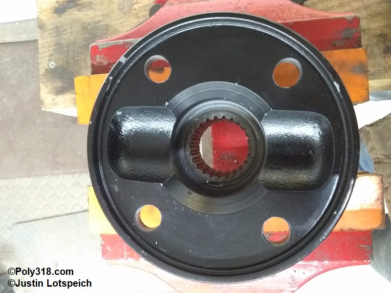
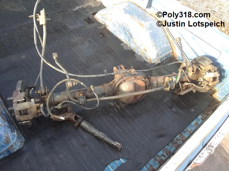
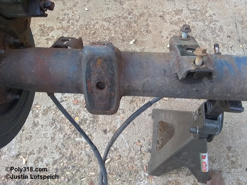
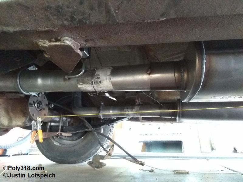
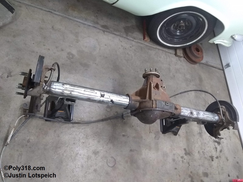
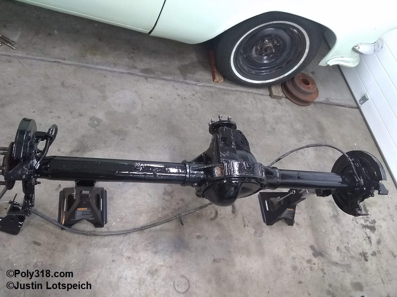
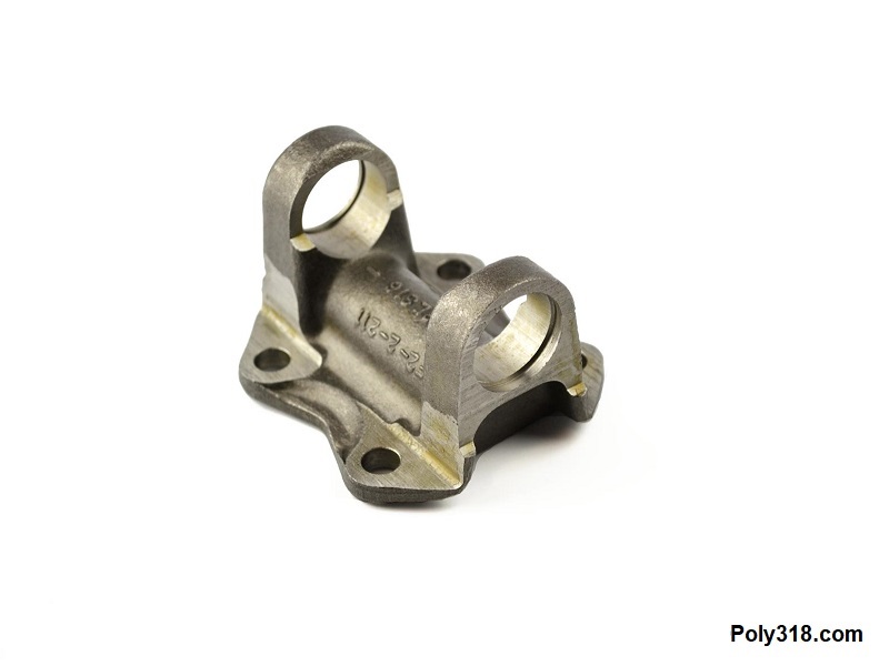
After carefully inspecting the assembly for any damage and verifying the differential listed on the cover tag, I found that the forklift driver at the salvage yard had stabbed one of the shocks with the fork and clipped the brake hose, but everything else was fine. Using a drain pan, I pulled the cover and inspected the gear oil and housing floor for debris but found nothing unusual. I unbolted the driveshaft. I confirmed the assembly had posi and counted the ring and pinion teeth, inspecting them closely as I went, to calculate and confirm the ratio at 3.73. After jacking up the rear and repositioning the jack stands, I cut the emergency brake cable where it exited the floorboard to where I have plenty of cable to join to the 1956 cable using an adjustable bracket I will make. I pulled the shocks, the trailing arm front bolts, u-bolts, sway bar links, and the rear leaf spring shackle bolts. I lowered the rear of the leaf springs onto the ground and slide the axle assembly back and out from under the car. My salvage yard charges a set amount for the entire axle assembly, so I didn’t bother removing parts; if they had charged for individual parts, as many do, I would have removed and left the sway bar and trailing arms since the 1955 – 1956 Dodge and Plymouth setup won’t allow the use of the swaybar because it interferes with the shocks. After $140 at the cashier counter, I loaded everything into my truck and headed home (Figure 1). After closely inspecting the assembly at home, I planed on going through the unit including new seals, new emergency brake shoes, new emergency brake shoes and hardware,
Prepping the 1956 Dodge
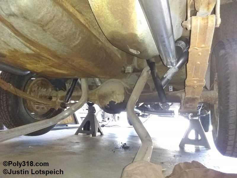
To prepare the 1956 Dodge chassis for the 8.8″ rear end, I performed the following steps:
- Place the front and rear chassis rails on jackstands high enough to work underneath the car. I place the rear jackstands on the side rails as far back toward the rear bumper as possible to allow room to work on the leaf spring shackles.
- Apply penetrating oil to the rear end u-bolt nuts/threads, shock mount nuts, front leaf spring mounting bracket nuts, front leaf spring eye bolts, leaf spring shackle nuts.
- Remove the brake hose from the chassis brake line.
- Remove the u-bolts, mounting plates, and shocks.
- With a floor jack placed under the left leaf spring until it just touches the spring, remove the front leaf spring mounting bracket. Lower the floor jack to the ground and pull out the jack so the left leaf spring and left side of the rear end rest on the ground.
- Repeat step 5 on the right side.
- At this point, the rear end may be slid/rolled forward on the ground to release any pressure on the leaf springs.
- Remove both shackles and leaf springs. The shackle bolts are usually extremely corroded and require prying and possibly using a hammer and drift to punch them out. Silicone spray can help.
- Remove the front leaf spring eye nut, bolt, and mounting brackets from the leaf spring.
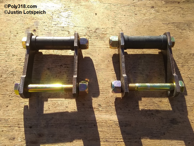
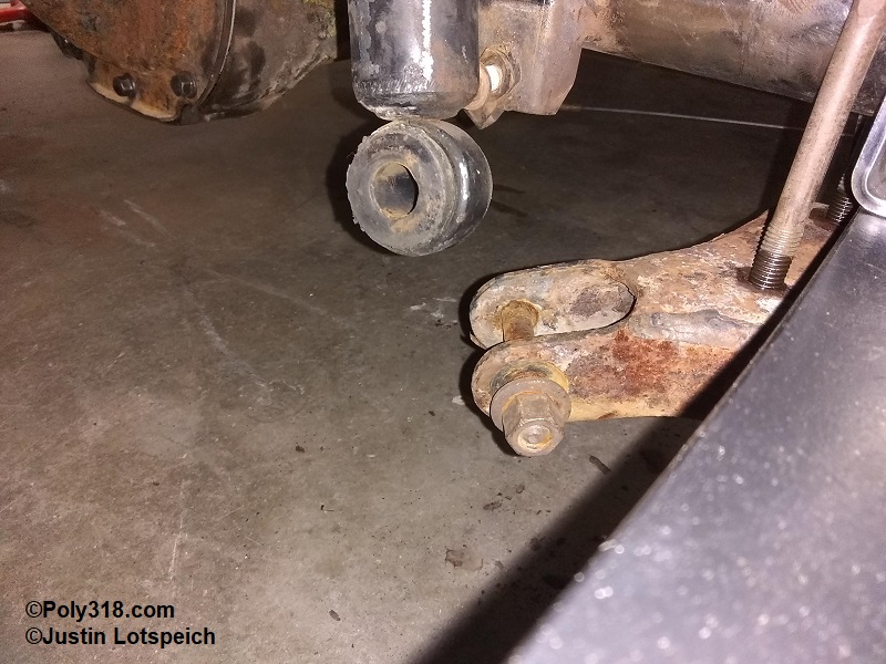
- My shackle bolts were heavily corroded, so I rebuilt them (Figure 2). I explain this process in the article on leaf springs and shackles.
Prepping the Ford 8.8″ Rear End
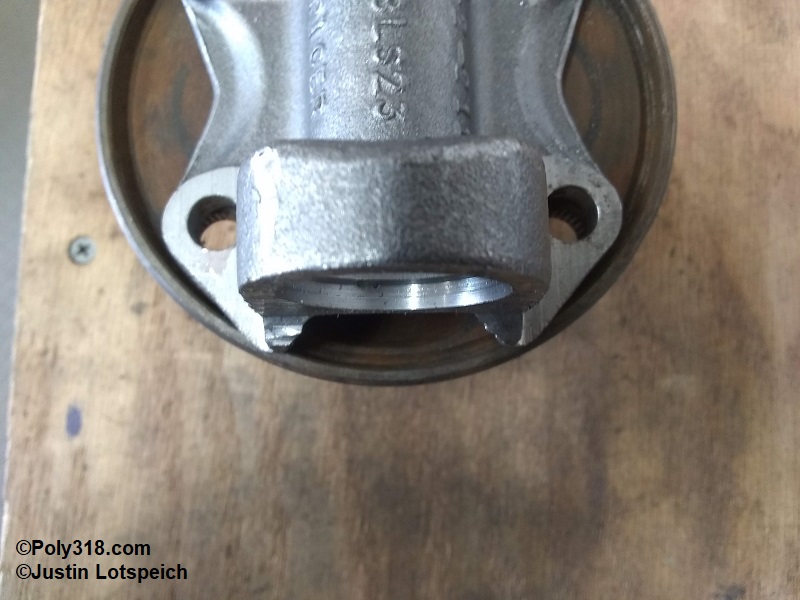
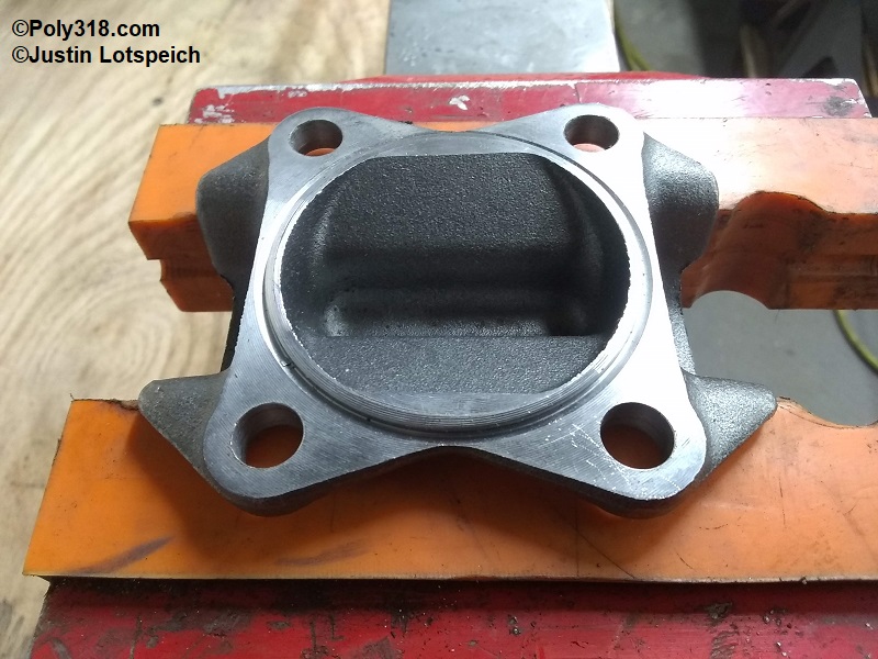
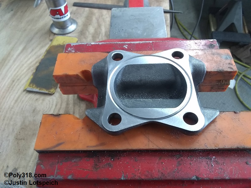
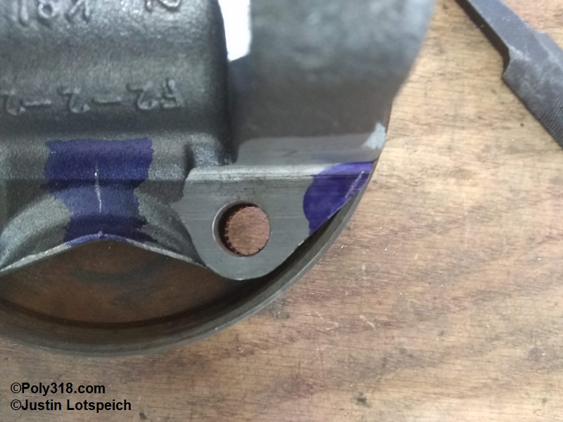
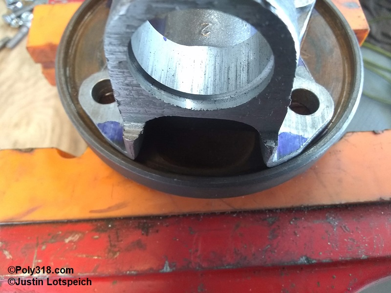
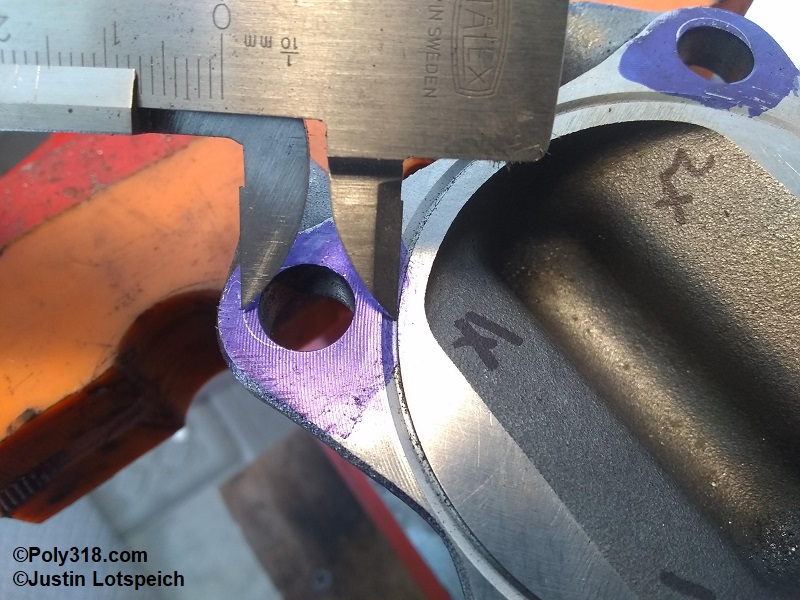
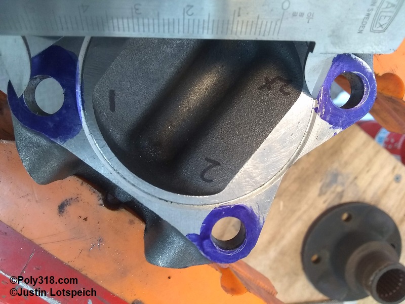
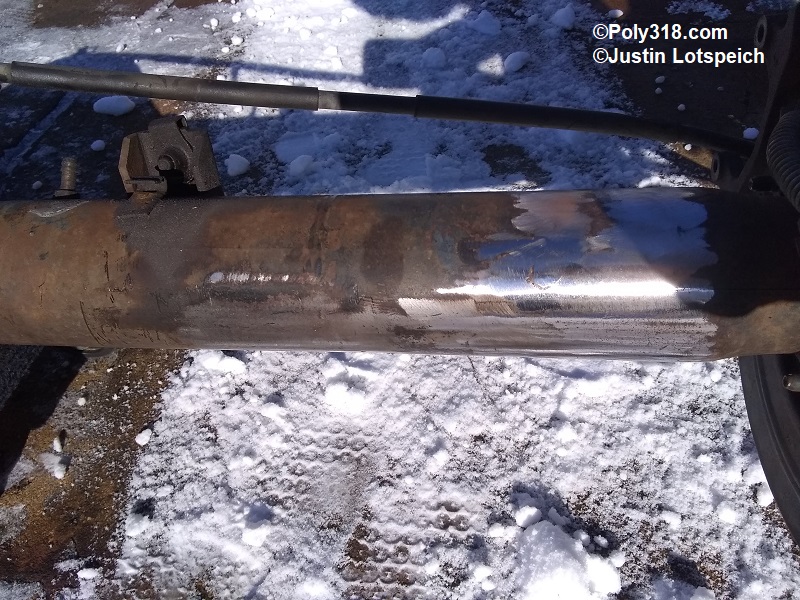
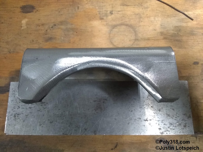
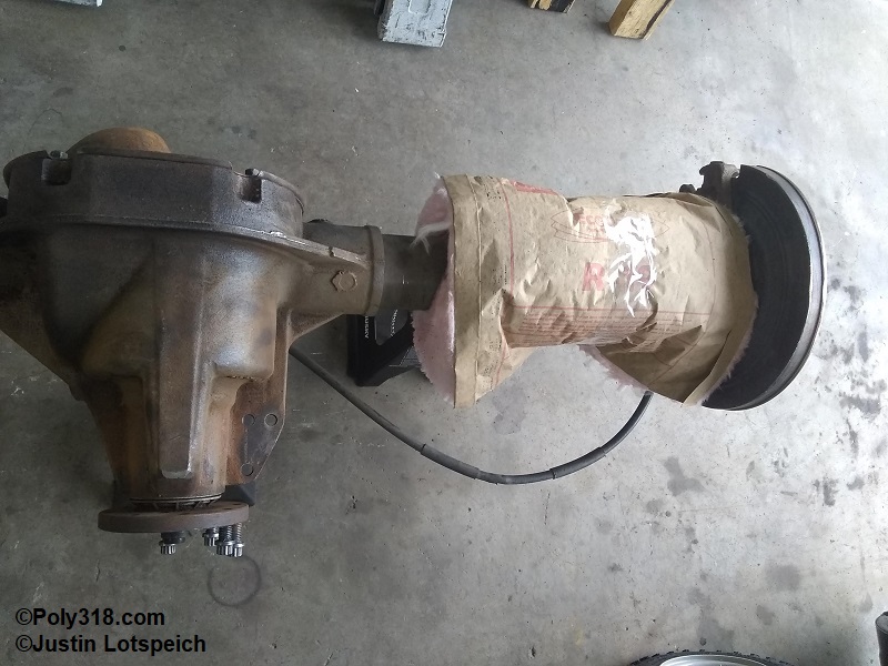
The 8.8″ leaf spring perch locations are too inbound and need to be removed. The link bar brackets interfere with the new spring perch locations and need to be removed. Using a cut-off wheel in an angle grinder, I cut off the spring perches and link bar brackets being careful not to cut into the rear end housing. Switching to an 80-grit sanding disc on the angle grinder and clean up the cuts until the housing is smooth and at down to bare metal from the original perch location toward the brakes to where the housing tapers to allow for welding on the new spring perches to clean metal (Figures 3a and 3b). I purchased a pair of spring perches for a 3″ diameter housing and massaged them with a sanding disc to fit the 8.8″ 3-1/4″ housing. The perches create a “T” joint against the housing, so to focus the weld bead at the center of the perch material’s thickness and keep the bead at a minimum width (less heat zone), I beveled the bracket edges at about 45° (Figure 3c).
Leaf Spring Consideration to Correct Factory Shackle and Spring Arch Geometry Flaws
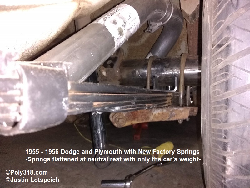
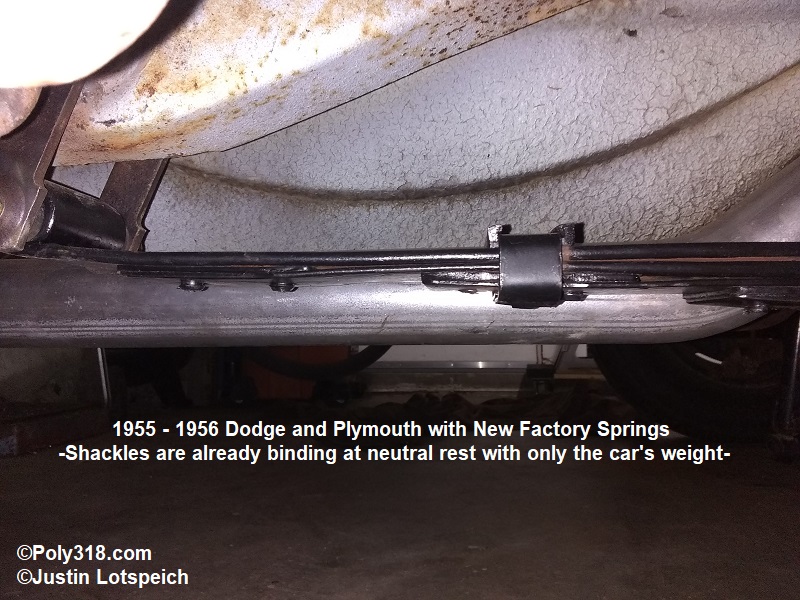
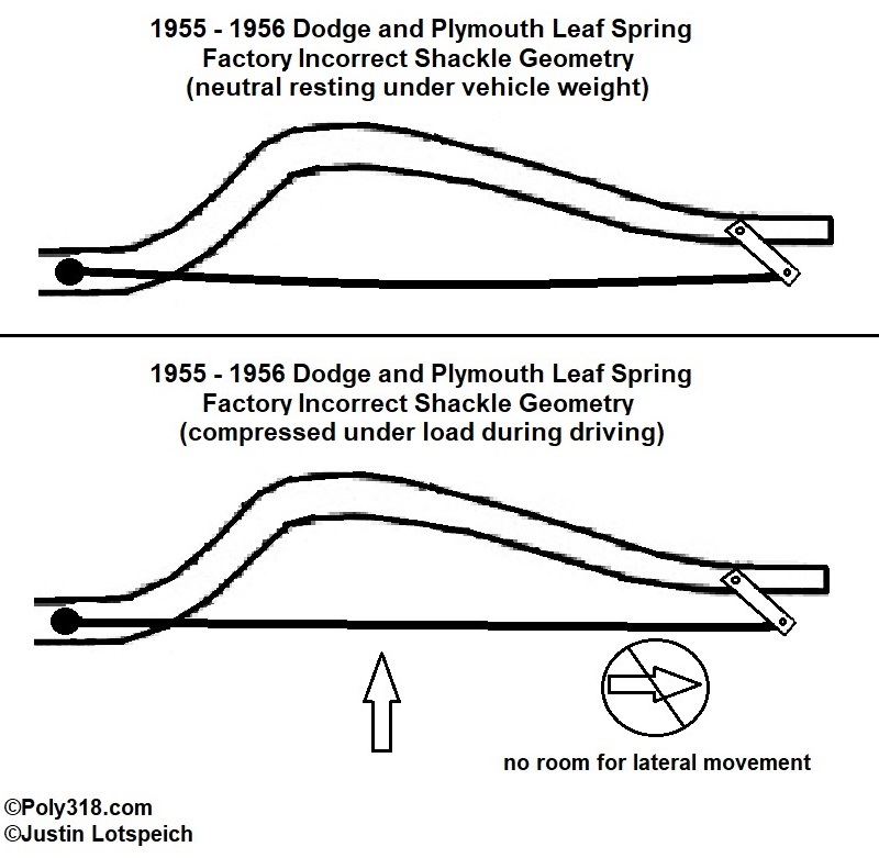
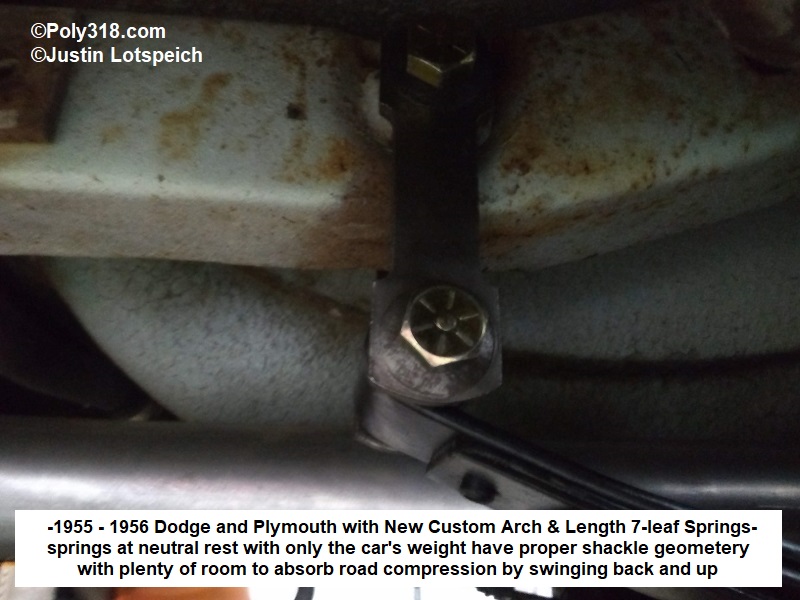
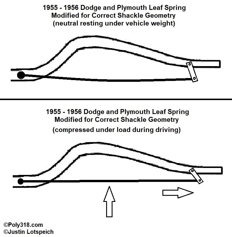
As I discuss at great length in the article on 1955 – 1956 Dodge and Plymouth leaf springs, 1955 – 1956 Dodge and Plymouth passenger cars have significant design flaws in their shackle geometry and load capacity. Depending on how you approach the shackle issue, either the leaf spring is too long eye-to-eye or the chassis shackle boss is placed too far forward. The front spring eye is fastened to the chassis to where it cannot move laterally and only rotate on the eye bolt. The rear spring eye should be hinged via the shackle, allowing the leaf spring to flatten and arch as the chassis is loaded and unloaded during driving. Figures 4a – 4b show stock 1955 – 1956 Dodge and Plymouth rear suspension neutral at rest under the vehicle’s weight. From the factory, the brand new springs rest almost flat with practically no arch. Notice the angle of the shackle is swung at a drastic angle back and up toward the chassis to where it is already binding, as in it has no room to swing back and up to absorb and therefore cushion additional load from passengers or during driving. The factory angle essentially fastens the rear eye to the chassis similar to the front, leading to more road vibrations/bumps being felt by the occupants since the bound shackle has no room to absorb additional loads as the spring desires to flatten out and become longer from eye to eye. At the same time as the shackle geometry issue, the the springs are too weak being flattened out where as passengers and luggage are loaded and as additional loads are pressed down onto the spring during driving, the ride bounces more as the spring is forced to go negative in arch and want to spring back flat (Figure 4c).
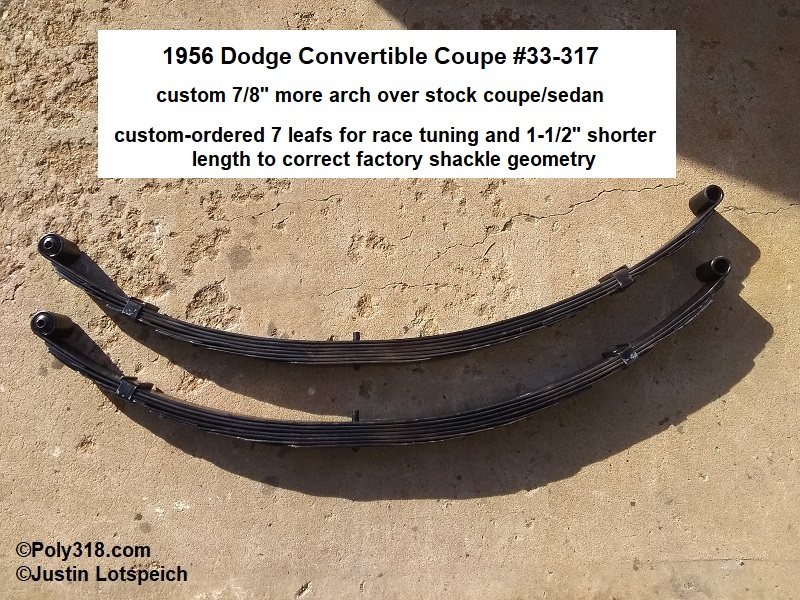
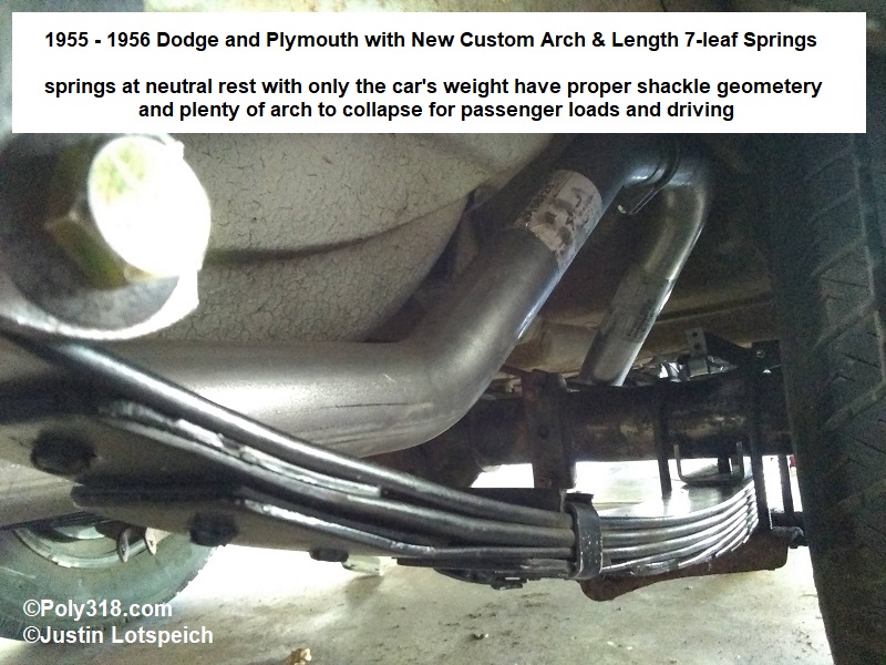
To correct the design flaws and improve the rear suspension, I had ESPO make a pair of custom spring shorter at 47-1/2″ eye-to-eye unloaded and with seven leafs for better spring rate with the second spring from the top extending under the first leaf’s eyes for better support (Figure 5a). I also had the spring made with 8-3/4″ free arch, 1″ more arch than the factory coupe/sedan spring. These modifications brought the shackle angle to a correct plumb orientation and allowed the spring to maintain a healthy arch as seen in Figures 5b – 5d. A crucial consideration here is that the shackle is almost plumb with a 1° negative angle (leaf-spring eye farther toward the rear than the chassis connection) so that the shackle more naturally wants to swing back and up under road loads. Note that with my custom 47-1/2″ spring design, I had to secure the shackle end first and then use a C-clamp to lightly compress the front spring eye bracket up against the chassis mounting bracket in order to start the four bolts.
Another benefit I designed into the new springs was increased ride height and therefore rake in the back. With new factory coupe/sedan springs, the front and rear rocker panel height off the floor were dead level at 10″. With my custom springs at 47-1/2″ eye-to-eye that pulled the rear eye about 1″ down toward the ground, 8-3/4″ free arch, and a seventh spring, the ride height raised 2″ over the stock configuration for a nice 2″ rake that fits the form and function of the hot rod.
Installing the 8.8″ Rear End
I acquired the following parts for the installation:
- Pair of new leaf springs (see Figure 5a and discussion above).
- Pair of heavy gauge 3″ or 3-1/4″ housing leaf spring perches. The 8.8″ Explorer housing is 3-1/4″ diameter, so I had to grind the 3″ perch bird’s mouth cuts slightly until they fit snugly around the 8.8″ housing.
- Eight Moog K7308 shackle bushings.
- Pair of Monroe 66859 gas shocks, which I selected from scouring parts catalogs after installing the 8.8″ rear end and measured the needed extended and compressed length. This particular shock was used on 1970 Dodge P300 vans for those wanting to cross reference.
- Eight new 3/8 bolts (Grade 8) and nylock nuts for the front leaf spring mounts.
- (2) axle seals, (1) pinion seal, (1) new pinion crush washer, (1) differential cover gasket, new gear oil, new parking brake shoes and hardware, and new brake pads.
I placed the 8.8″ under the chassis up on jackstands high up to where I could fit the leaf springs below them without the axle interfering. I installed the shackles to the leaf spring and chassis first. I swung the front of the leaf spring with attached bracket up where the bracket contacts the chassis flange and secured the bracket with two of the four 3/8″ bolts. Note that with the shorter 47-1/2″ custom springs, I had to use a C-clamp to lightly bring the spring bracket toward the chassis mounting bracket in order to get the nuts started.
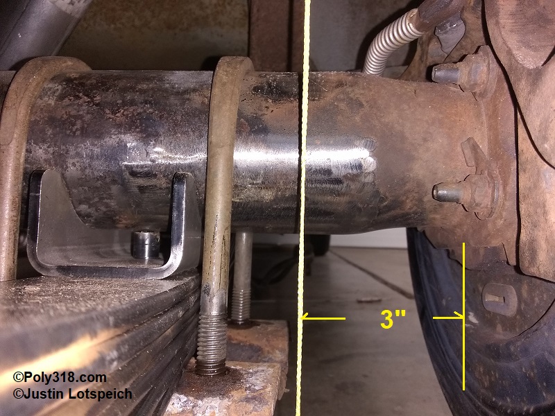
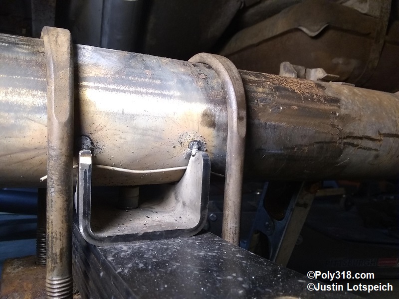
At this point, the leaf springs are installed and hanging. I placed the spring perches over the leaf spring studs and lowered the rear end onto the perches. For welding the perches, it is important to have a gap between the perch and housing about 10% the width of the perch material to allow for good weld penetration. To form this gap, I slide a piece of rebar tie-wire between the perch and housing (the photo I took was too blurry, but you can see the tie-wire gap in Figure 8a below). I attached a plumb bob to the outside of each frame rail just behind the rear axle in order to center the axle. For my chassis, I found that the outside frame rail plumb line to the inside of the axle flange is 3″ to center the axle (Figure 6a), although this measurement should be checked on the specific vehicle. I installed the u-bolts, mounting brackets, and nuts snuggling down the nuts enough to hold the rear end from rotating under its own weight but loose enough to move the pinion up or down using a pry bar or mallet.
Confirming the axle is still centered, I moved on to setting the pinion angle. The pinion angle is a complex measurement that I detail in another article that can be reviewed. After setting the pinion angle, I confirmed the axle was still centered using the plumb lines and placed a strong tack-weld at each corner of the spring perch to secure the perch to the housing (Figure 6b).
Setting Pinion Angle
While I wrote and entire article dedicated to the complexity of setting pinion angle, I cut to the 1956 Dodge swap here and don’t go through all the theory and equations. If the terminology and math below doesn’t make sense here, please review that longer article. With the Dakota front clip, new leaf springs, and Ford 8.8″, I was starting from scratch and had to set the transmission output shaft angle and rear pinion angle before I could weld the new spring perch pads to the axle housing. I also had no drive shaft and needed to measure that to have one made.
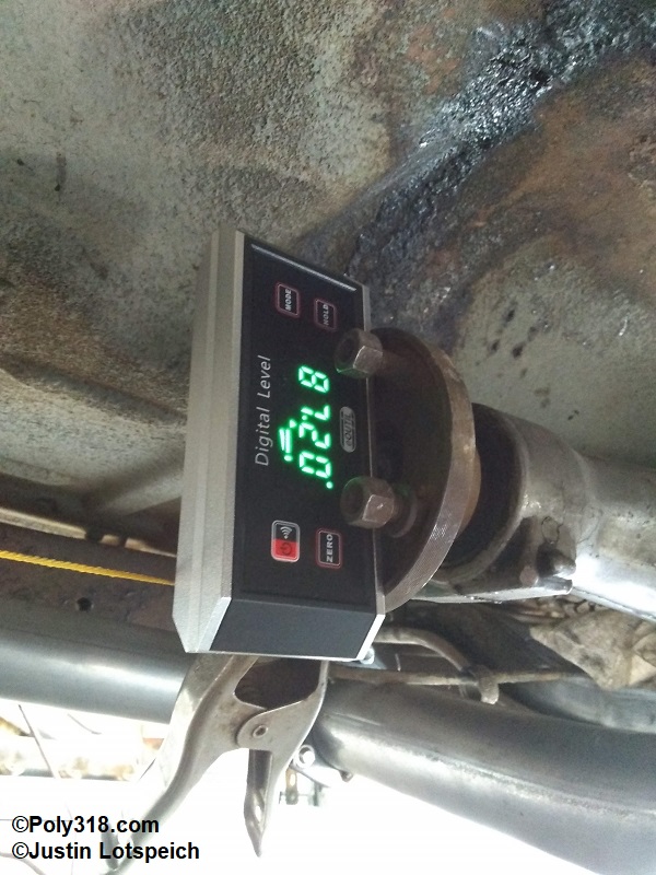
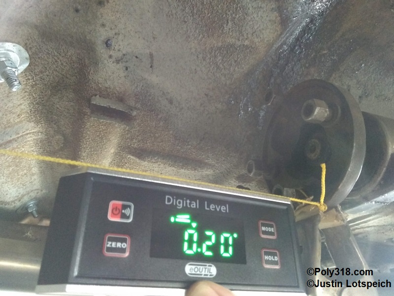
Since I fabricated the engine and transmission mounts, I was able to set the intake pad level that placed the output shaft at 2.8° negative slope when viewing from the left (driver) side of the car (Figure 7a). Note that the digital protractor is measuring based off 90° vertical, so 90 – 87.2 = 2.8°. With the rear axle u-bolts tightened just enough to hold the housing from rotating on its own but allowing me to rotate the housing using a mallet, I adjusted the pinion angle to 2.8° negative slope (nose up) in order to get my drive shaft angle. I measured out from the transmission output shaft center and clamped a string-line to the flange. I measured out from the pinion center the same distance as the output shaft flange and clamped the taut string-line to the pinion flange (Figure 7b). For this mock-up, the output shaft angle matches the pinion angle to mimic where the two will be with +- 1° of each other at a sustained 50 MPH driving down the road assuming 1° – 3° of axle wrap (I discuss axle wrap calculation in the longer article). I carefully brought the protractor up to the string and captured the drive shaft angle at 0.20° (Figure 7c). I’d ideally like a little more angle here, but I wasn’t able to raise the transmission any more before hitting the body tunnel or lower the rear axle (via longer shackles or more arch in the leaf springs) since the car was at the rake I desired. Now that I had the necessary angles, I did the math:
Output shaft: 2.8° negative slope (tail down)
Drive shaft: 0.20° negative slope (drive shaft down in the back)
Front U-joint operating angle: 2.8 – 0.20 = 2.6°
Armed with the front u-joint operating angle, I calculated where I needed to set the pinion angle. The custom rear leaf springs are stouter than stock, so I don’t anticipate more that 2° of axle wrap at a sustained 50 MPH. If I find that I get more axle wrap, I plan on fabricating traction bars that will allow me to lock out axle wrap. I did the pinion angle math:
Output shaft angle slope: negative (tail down)
Front U-joint operating angle: 2.6°
inion angle building in 2° axle warp: 2.6 – 2 = 0.6° negative slope (nose up)
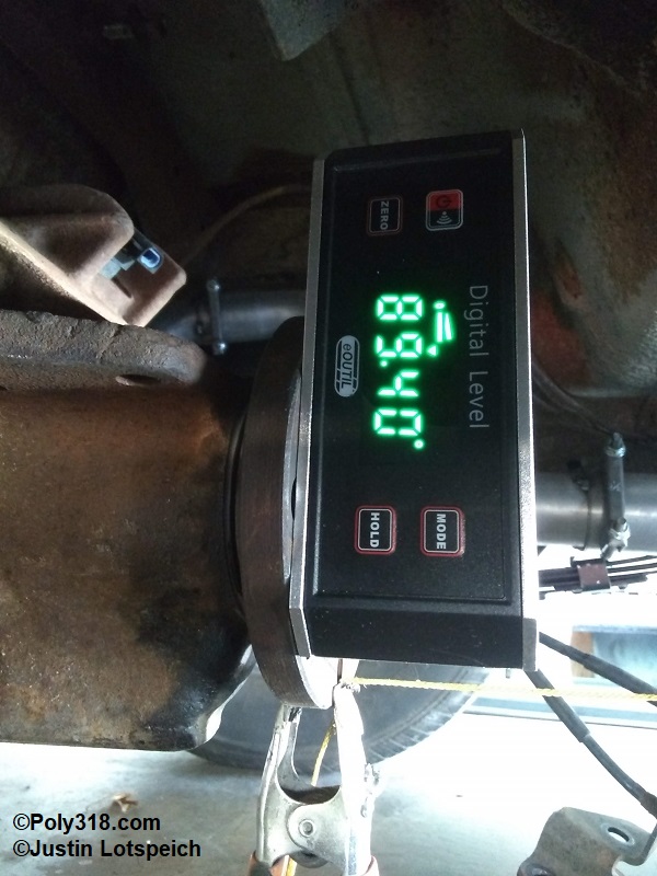
Using a mallet, I tapped the pinion until I had the flange set at 0.6° negative slope, nose up (Figure 7d). Note that as with the output shaft, the protractor is measuring from 90° vertical, so 90 – 89.4 = 0.60°. I snugged down the u-bolts and checked the angle again to find that the axle rotated slightly when the leaf spring flattened against the perch, so I loosened the u-bolts and adjusted the pinion angle until it remained at 0.60° with the u-bolts snugged down.
With all the angles calculated and the pinion angle set, the output shaft and pinion slopes match at negative slope (output shaft down, pinion nose up), the front U-joint operating angle will be 2.6° within Spicer’s drive shaft rpm allowances at the engine’s 6,500 redline and the vehicle’s likely track top speed of 110 MPH, and the pinion angle will be matched at sustained 50 MPH within +- 1° between 1.6° and 3.6° depending on the amount of axle wrap.
Welding the 8.8″ Spring Perches and Finishing the Housing.
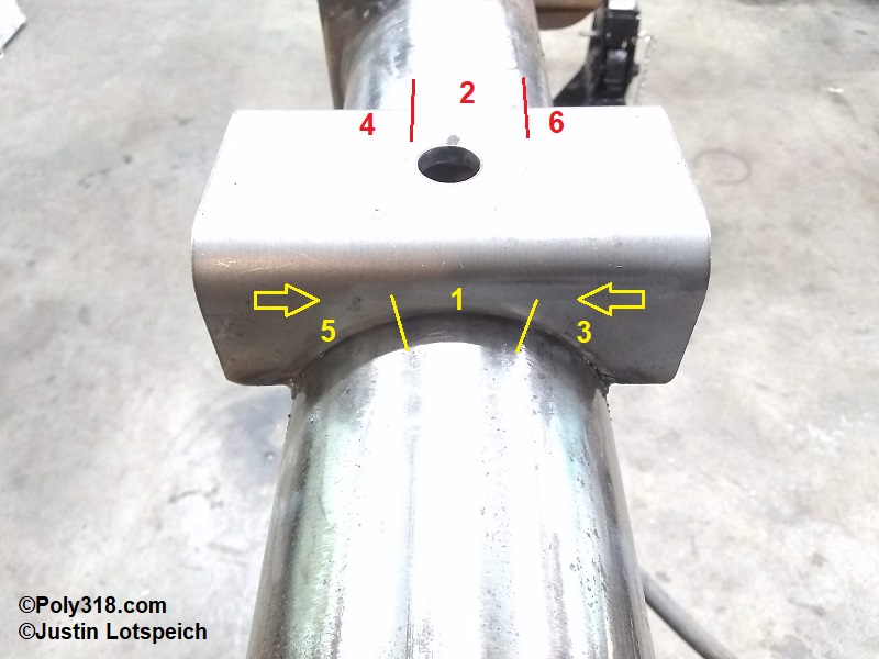
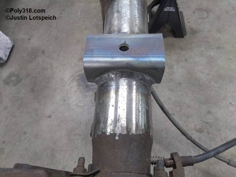
With the pinion angle set, I tack-welded the spring perch pads to the axle housing at the four corners in preparation for removing the housing to finish the welds (Figure 8a). After I removed the rear end and placed it on jackstands, I used pliers to remove or break off the tie-wire used for the gaps and brushed off any flux from the tack welds. I don’t have a jig bar of the proper diameter to run through the 8.8″ housing, so I opted for more involved approach. Since I had already drained the gear oil and knew I would be replacing all the seals, I left the axle assembly intact. With the housing positioned on the jack stands, I set up a laser pointer on a nearby surface and took pre-welding measurements from the laser down to the housing at three different points on each side of the center section as a baseline to gauge if the housing warps during welding. Focusing on one perch at a time, I preheated to 2,000°F the housing tube from the perch around the tube back up to the perch and preheated the perch itself. This action helps expand the steel’s molecular structure and equalize the heat zone to help offset shrinkage as the metal cools after welding. The key is to keep the heat relatively consistent in the material during the entire welding process. Using my 180A MIG, I placed a 1″ long bead at the center of the perch on both sides of the perch one directly after the other. From here, I used 1″ long back-step welds in an “X” pattern jumping from one side of the perch to the other side of the perch stopping only long enough to knock and wire brush off the flux. The reason I used an “X” pattern is to allow the bead I just placed to cool slightly so as to not overheat the material (thus limiting the heat affected zone), but I worked in a constant series of welds to keep the heat in the material to limit shrinkage due to repeated cooling between welds. For the welds at the ends of the perches, I wrapped around the corners and up the inside 1/4″. In Figure 8b, I number the weld sequence and placed arrows to show the direction of my back-stitch welds (melting the new bead into the previous bead), and Figure 8c shows the finished weld. As soon as I finished the first perch, I used the torch to heat around the housing and the perch to 2,000°F like I did for preheating to equalize the heat affected zone. I then wrapped the perch/housing in a piece of R19 fiberglass insulation to slow down the cooling process as long as practically possible to anneal the welds/heat affected zone more so than if I didn’t wrap the material (Figure 8d) . On prior experiments, I found that the housing wrapped in R19 fiberglass takes twice as long to cool to room temperature than an unwrapped housing, so it makes a bid difference. I repeated the preheating, welding, post-heating, and cooling processes on the other perch. After the housing cooled to ambient temperature, I removed the fiberglass insulation and took my laser measurements at the same points to confirm that the housing did not warp even 1/32″.
I’ve known hobbyists who have done none of my process and simply laid down a 4″ long bead on both sides of the perch, and I’ve known hobbyists who have done none of my process and laid down 1″ stitch welds allowing the material too cool for minutes between welds. Of these projects, I’ve seen some rear ends survive on the road, which I ascribe to luck more than the welding process, and I’ve seen others warped so badly that they ate up axle bearings within a thousand miles of use. Some may dismiss my process as overly anal, but it’s how I was taught in a body shop to limit steel fatigue and warping when welding suspension parts and frames where appropriate and when we didn’t have a jig and building one wasn’t economically feasible.
With the welding completed, I removed the calipers, rotors, emergency brake shoes/hardware, and axle shafts. I removed and replaced the axle seals, inspected the axle bearings (they were clean and undamaged), coated the bearings in fresh gear oil, and reinstalled the axle shafts. I removed the pinion flange, pinion seal, and discarded the crush washer. I installed a new crush washer and seal and reinstalled the pinion flange. I cleaned out the center section of residual gear oil/dust and installed the differential cover with a new gasket. At this point, before installing the emergency brakes, rotors, and calipers, I prepped, primed, and painted the housing, backing plates, and axle flanges with POR 15 chassis black (Figures 8e – 8f).
Shock Absorbers
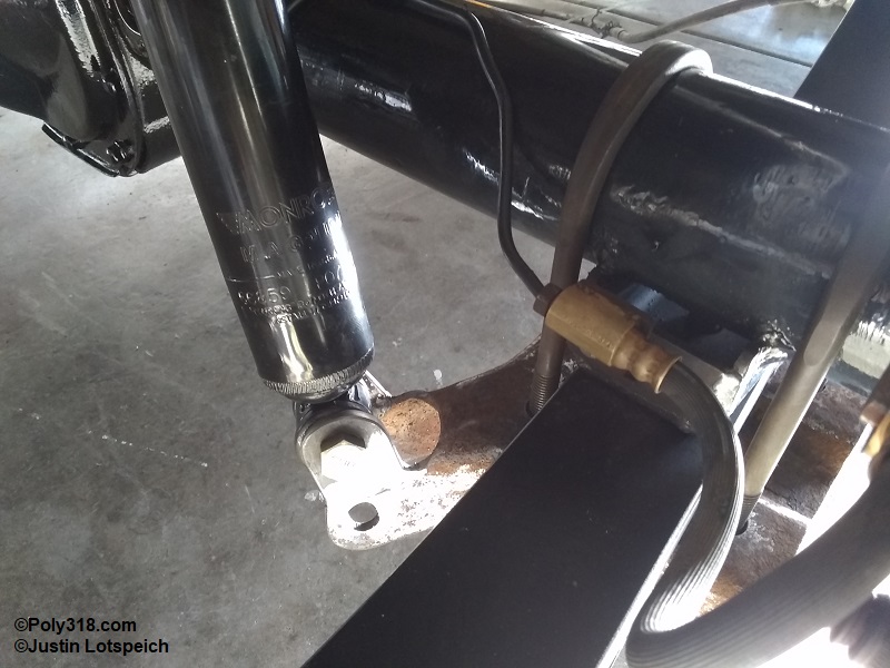
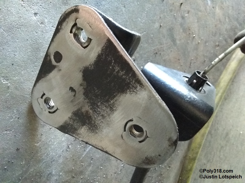
When dealing with the shock mounts, I couldn’t maintain the slick 8.8’s brake hose/line setup and place the shock mount on the perch like the original 1956 mount. The most obvious alternative was to make the 8.8″ shock mounts located on the plate work, but these turned out to be problematic. Figure 9a shows the factory 1956 Dodge shock in comparison to the 8.8″ shock mount that I will use. I measured the fully extended length needed for the shock from the chassis stud down to the factory 8.8″ mounting bracket hole with the axle dangling fully unloaded. Then I placed the car back on the ground and had four family members and friends sit in the car. I measured from shock mount to shock mount and subtracted another 3″ to allow plenty of room for suspension collapse during driving. The shortest measurement is the minimum collapse I need, and the longest measurement is the minimum extension I need. After spending a couple hours scouring online parts catalogs, I settled on the Monroe 66859 used on 1970 (and other year) Dodge P300 vans.
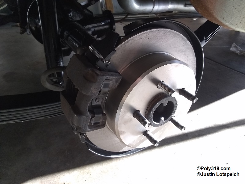
The next issue was the angle of the 8.8″ mounting ears compared to the angle of the shock coming down from the upper chassis mounts. Simply put, there was no way I could heat and bend the ears in a way that wouldn’t look hacked, so I settled on fabricating four new ears and welding them onto the plates. Figure 9b shows the new mounts, and figure 9c shows the brakes rebuilt aside from painting the rotor center chassis black.
Parking Brake System
With the 1956 parking brake located at the tail of the PowerFlite, the car no longer had a parking brake. I suppose some people would just ditch the parking brake, but I want one as a mechanical fail-safe and for parking on hills/mountains. Luckily, the 8.8″ disc brake rear ends have a slick mechanical parking brake setup that uses a set of small brake shoes that ride inside the rotor, which acts as the brake drum. The factory cables from each side join just in front of the axle assembly and continue as a single 1/8″ diameter cable up to the factory parking brake pedal assembly. When I pulled the rear axle assembly from the donor car, I cut the parking cable just as it came out of the floor and took all the cable and bracket system except for the pedal assembly. The single cable has two factory splices, and the forward most coupler is necessary for repurposing.
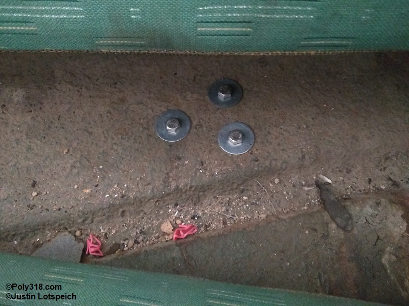
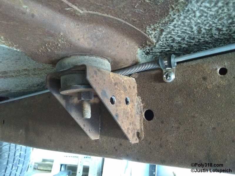
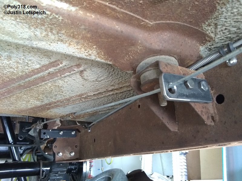
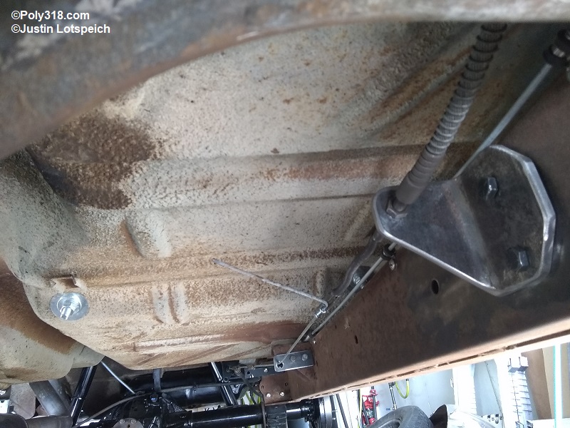
When fabricating the parking brake system, I started from the rear and work forward. To begin, I expanded the new parking brake shoe adjuster on each side until the rotor wouldn’t slide on and then backed off the adjuster until the rotor just slid and seated onto the hub. This position is good for fabrication and won’t create parking-brake drag after the new shoes and rotors scuff into each other. Ford used a couple different rear mounting brackets for the cables depending on the year of the Explorer. The 2001 Explorer incorporates the bracket into the left rear strut mount. I had multiple obstacles to avoid when considering mounting and cable routing including the exhaust over the rear end, rear brake hose, front leaf-spring mount and exhaust bracket, muffler, middle body mount bracket, and the two-into-one cable coupler clearance from the floorboard. The suitable location I found to mount the bracket through trial and error was on the underside of the floorboard under the rear seat with a slight angle toward the left frame rail to bring the cable back toward the frame rail so it would align with the 1956 Dodge hand-lever cable and clear the exhaust head pipe. I hammered and spot welded 3/8″ nuts into the large factory bracket holes to create threaded bosses, drilled through the floor, and fastened the bracket using 3/8″ bolts, lock washers, and fender washers (Figures 10a – 10c).
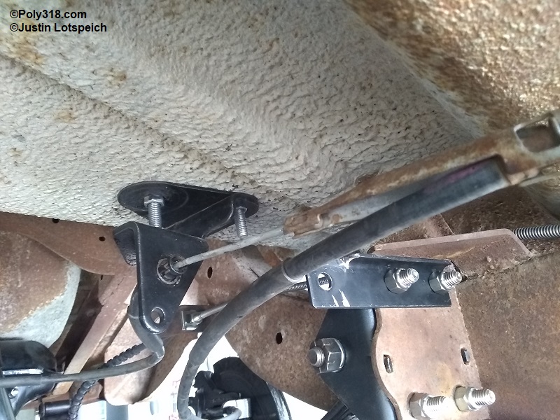
The next consideration was bringing the single 8.8″ parking cable down in elevation to about halfway on the frame rail and 2-1/2″ off the frame rail from that point forward. To secure the cable in this route, I fabricated a bracket from 3/16″ steel strap that mounts to the middle body mount bracket using two 5/16″ bolts/nuts. I drilled a 3/8″ hole in this bracket, heavily chamfered both sides, and used a sanding drum in a die grinder to polish the bore and chamferes into a smooth rounded edge to allow the cable to slide without damage (Figure 10d – 10e); in comparison, the Ford Explorer uses a 3/16″ wire hoop that sticks into the frame rail, but this wire bracket was too long for my configuration.
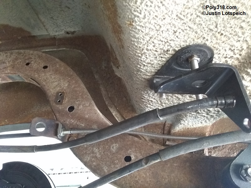
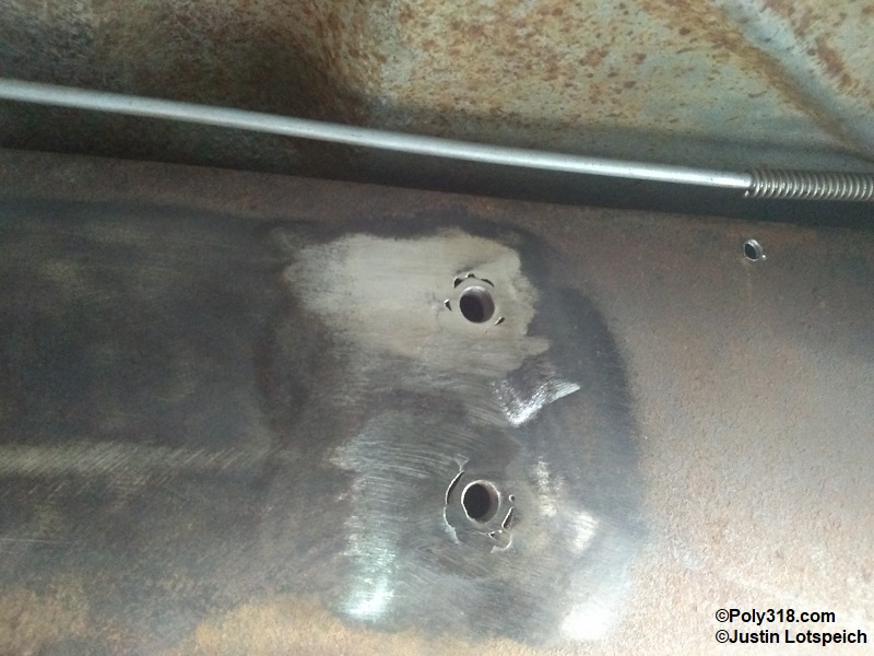
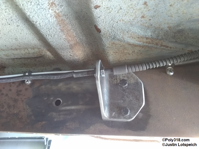
The final bracket secures the 1956 hand-lever cable adjuster end and bears the force of the tension when the parking brake is applied. To avoid any future issues with the bracket flexing and to eliminate the need for gusseting the bracket, I built it from 3″ x 3″ x 1/4″ angle iron and contoured the shape for aesthetics. The bracket includes two 3/8″ mounting holes and a 3/8″ hole through which the cable adjuster runs. I located the bracket laterally to where the hand-lever cable routes away from the master cylinder brake lines and in an aesthetically pleasing way in the engine bay. It is important to place the bracket where the final hand-lever adjuster lands about halfway in its threads to allow for plenty of adjustment. The tension on the parking brake system would eventually strip out the holes if I simply drilled and tapped the inside of the frame rail, so I drilled the two mounting holes and welded 3/8″ nuts into the frame rails for fortified bosses (Figures 10f – 10g).
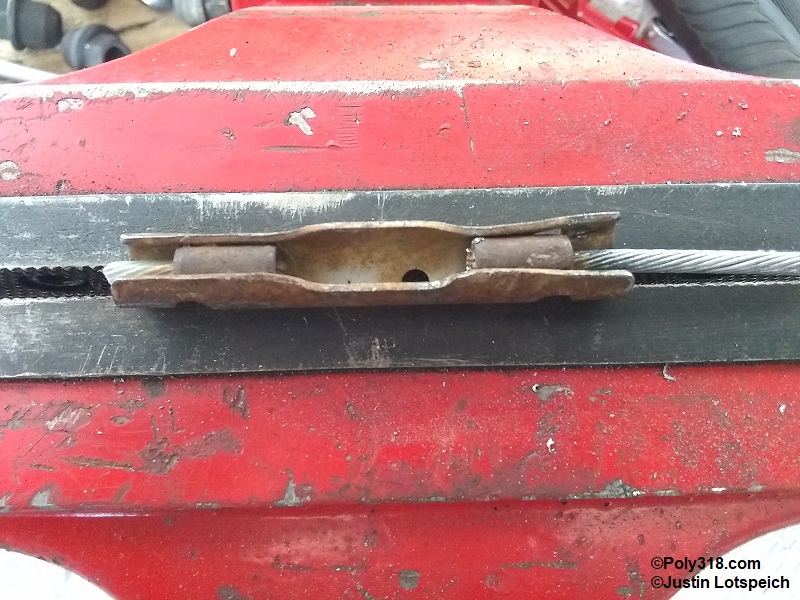
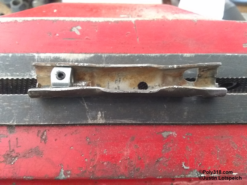
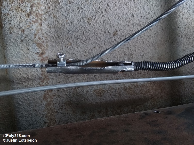
Connecting the 8.8″ cable to the 1956 cable in a way that allowed me to easily split the connection at a later time was the final hurdle. With my front bracket in its location, I had to cut the 8.8″ cable behind the front factory splice, so I devised a way to repurpose the factory coupler (Figure 10h). I used a cold chisel to lightly spread the coupler and drive out the factory ferrules. I massaged the openings using a hammer and drift on the bench vice to where a 1/8″ shaft collar fit snugly against the stop on one end and the 1956 cable ball ferrule fit snugly against the stop on the other end (Figure 10i). I installed the hand-lever cable into the chassis bracket with the adjuster nut choked all the way forward against the cable housing, which is the loosest adjustment. After sliding the 8.8″ cable through the collar/coupler and pulling it taught by hand, I secured the set screw that I had replaced with a hardened hex-head #6-32 machine screw so I could get good torque onto the cable compared to the wimpy 1/16″ Allen head set screw included with the collar (Figure 10j). Using a wrench, I threaded the adjuster stop nut in toward the back of the car to take out the slack from the cable system until I reached about the midpoint where the rear wheels locked up with the hand lever about halfway through its travel. Note that the photos show the 8.8″ cable running wild at the connection, which I will cut off and cap with heat shrink wire insulation after I have road tested and know I don’t need to make any major adjustments to the design. To disconnect the joint, I simply have to move the adjuster jam nut all the way forward, which allows enough slack to remove the 1956 ball ferrule from the coupler. Figure 10k shows the finished parking brake system from the front back.
Drive Shaft
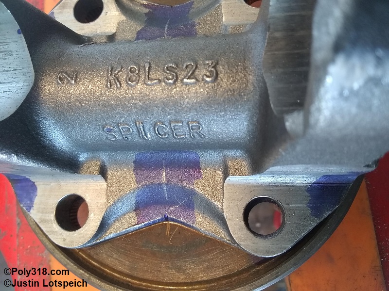
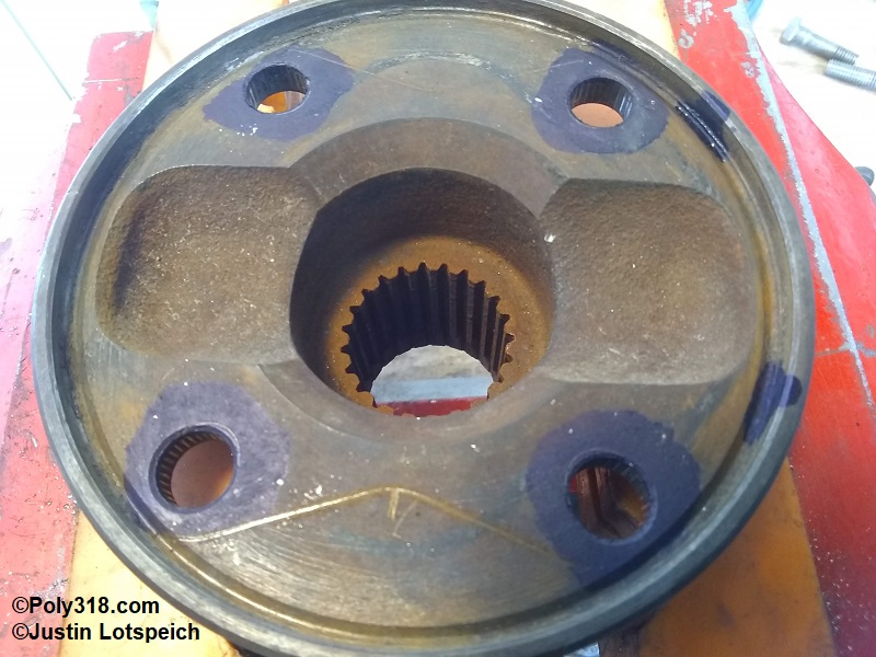
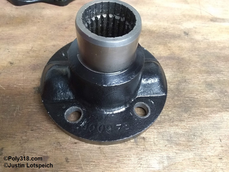
Now that the 8.8″ is installed along with a TorqueFlite 727, the factory 1956 Dodge ball-and- trunnion driveshaft isn’t going to work, nor would I want to run a vintage ball-and-trunnion on anything with decent torque. Pulling a tape measure from the face of the transmission output shaft flange to the face of the 8.8″ pinion flange, I measured 58-1/2″, which I provided to the driveline shop who calculated in all the necessary flanges and the slip yoke tolerances.
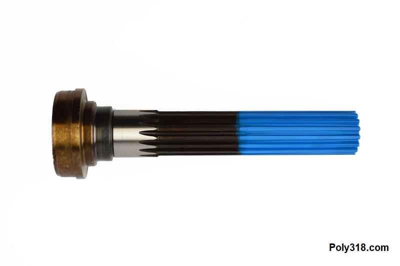
I did a great deal of research on the parts necessary for a slip-yoke drive shaft and confirmed the design with my local custom driveline shop that ended up building my drive shaft (photos forthcoming), but some variables come into play with the type of flange on the transmission output shaft and rear end pinion flange that one should confirm independently from the parts I list below since Mopar used different diameter flanges over the years. For example, the 1963 – 1965 A/LA/B/RB 727 output flange I’m using has a 3.25″ bolt circle and a 3-15/16″ diameter outer curb that originally kept the ball-and-trunnion flange captured and centered since neither the output flange nor the ball-and-trunnion flange has a male/female pilot. Currently available flange yokes (as of 2021) limit my options to the 1310 u-joint series, which are plenty strong for the vast majority of street-strip cars. According to Spicer, the cold-forged solid 5-1310X u-joint (no external greasing provision) is rated for 800 lb.ft. continuous load (like wide open throttle down the drag strip) and 1,600 lb.ft. of short-term load (like launching off the starting line). The 5-178X with its grease galleries is rated at 400 lb.ft. continuous, 800 lb.ft. short term loads. I’ve searched high and low for a 1330 or 1350 option to no avail, so if anyone reading this article knows of a 1330 or 1350 option that will fit or nearly fit the above output flange size parameters, please shoot me an email so I can update options here. At least for my build, I’ll never come close to 800 lb.ft. continuous or short-term, so I’m not worried about needing a 1330 or 1350 even though I use 1350 for the rear components for added security since they don’t really cost more. Of note, I think the 904s (V8 and S6) with fixed output shaft flanges may have used a smaller flange on their smaller output shafts since I’ve run across people online discussing a 2-7/8″ bolt circle flange, but I haven’t been able to confirm for myself since I don’t have a 904 output flange.
Parts List from Transmission to Rear End (in progress with build photos to come):
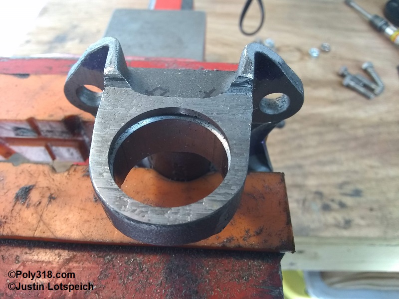
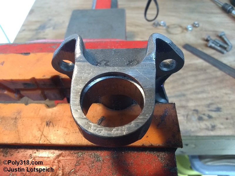
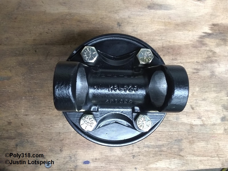
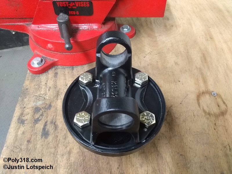
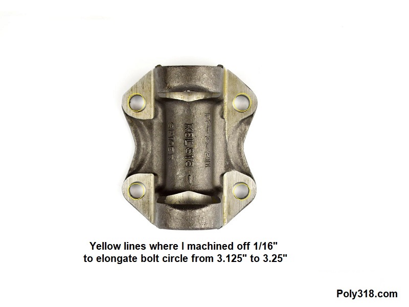
- Front Flange Yoke (to bolt onto the transmission output flange): Spicer 2-2-459 (1310 series, 3.125″ bolt circle, 4 bolt holes at .375″ diameter, 3.875″ outside circle, Figure 11a). This is the only suitable, available flange yoke I can find, and I had to use a carbide ball bit in an pneumatic die grinder to very slightly and carefully elongate the holes outward 1/16″ each for the flange to slip onto the 3.25″ bolt circle (Figure 11b). Note that the old Spicer 2-2-1769 in their catalog that is a nearly perfect fit is long since out of production. There is also a 2-2-389 flange yoke available with a 3.125″ bolt circle, but there isn’t sufficient material around the bolt holes to elongate them without weakening the flange beyond compared to the 2-2-459 flange yoke.
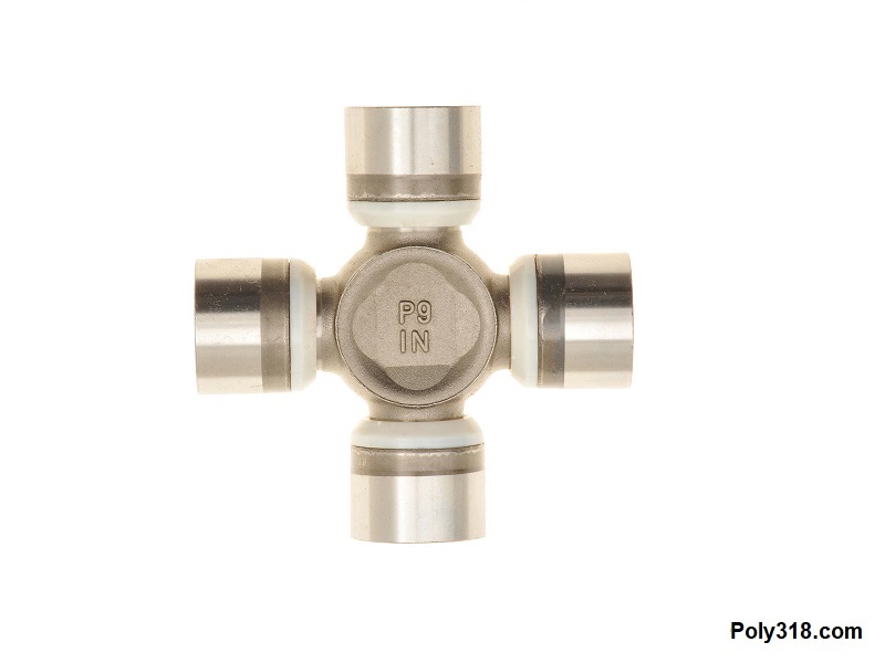
- Front Universal Joint: Spicer 5-1310X (1310 series, cold-forged, no grease galleries, Figure 11c)
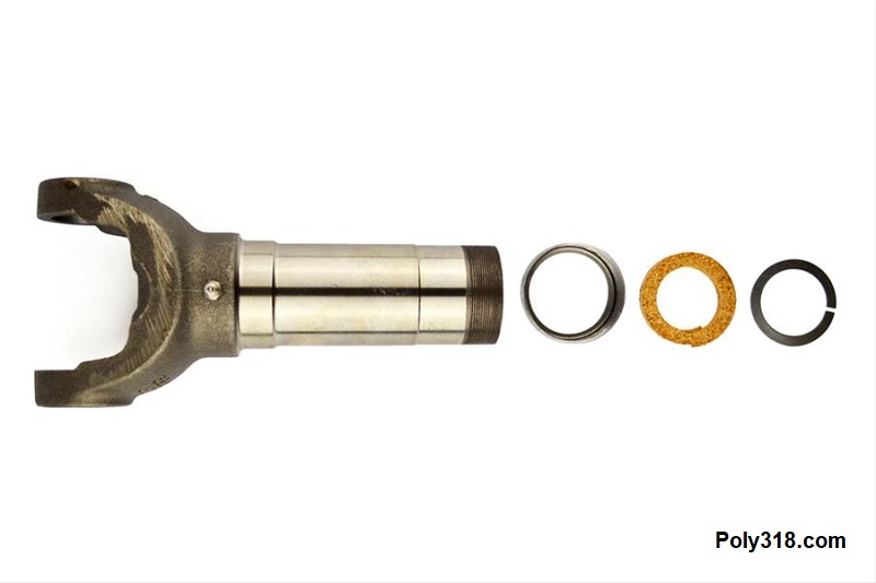
- Slip Yoke: Spicer 2-3-6061KX (1310 series, 1.5″ diameter x 16 female spline, 6.875″ from center joint to end, Figure 11d)
- Midship Shaft: Spicer 3-53-1531 (1.5″ diameter x 16 male spline, 6.58″ long splines, for 3″ x .083 tube, Figure 11e)
- Tube: 3″ x .083″ (long enough with the vehicle level on the ground at neutral rest under its own weight to allow the midship shaft to slide into the slip yoke leaving 1″ of free space for lateral movement before bottoming out)
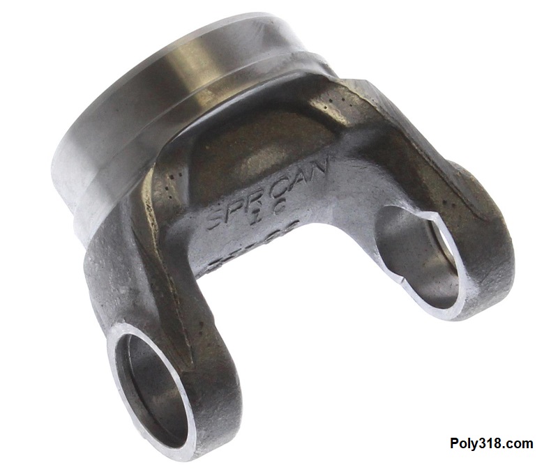
- Rear Tube Yoke: Spicer 3-28-57 (1350 series, for 3″ x .083″ tube, Figure 11f)
- Note: The rear tube yoke may require a different u-joint series depending on the rear end pinion flange. For example, if the pinion flange requires a 7290 u-joint, use a 7290 tube yoke.
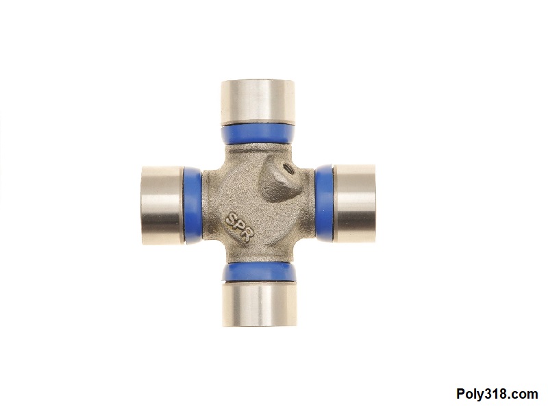
- Rear Universal Joint: Spicer 5-178X (1350 series, greasable, Figure 11g)
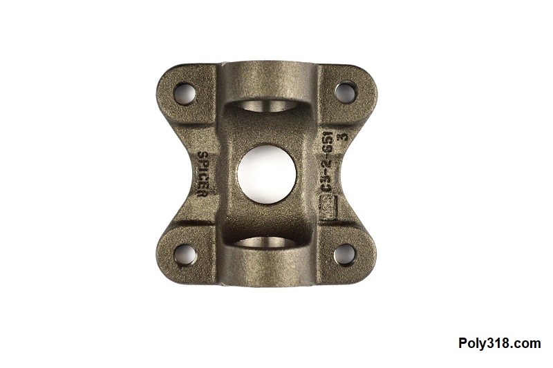
- Rear Flange Yoke: Spicer 3-2-1619 (1350 series, 4.25″ bolt center, 4 bolts holes at .472″ diameter, 2″ diameter pilot, Figure 11h)
- Note: This flange is only necessary when connecting the drive shaft to a version of the Ford 8.8″ with a flat pinion flange.
Modifying the Transmission Output Flange and Front Drive Shaft Flange Yoke
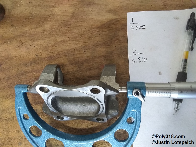
There are three issues with the output flange and Spicer 2-2-459 flange yoke: first, the output flange has a 3.25″ bolt circle when the Spicer flange has a 3.125″ bolt circle. Second, the output flange has a well diameter of 3.94″ when the Spicer flange has an outside circle of 4.10″ despite being advertised as a 3.875″ (Figure 12). Third, the Spicer flange has a male pilot on the backside that doesn’t allow the flange to rest flat on the output flange (Figure 13). To make the two flanges work, the stud holes need to be elongated, the Spricer flange perimeter needs to be carefully fitted into the output flange well, and the pilot on the backside of the Spicer flange needs to be machined off.
As soon as I received the Spicer flange, I realized I would not be able to elongate the stud holes outward enough to match the output flange’s bolt circle since there would be little material left around the holes to where the material could crack and tear away under a high-torque situation like launching at the drag strip with slicks. The only solution was to press out the output flange studs, elongate the holes inward to match the Spicer’s smaller bolt circle, and use bolts instead of studs. This solution wouldn’t have any negative impact since the Spicer flange would be centered and pinned in place inside the output flange well.
I addressed the pilot on the backside since I needed to remove it before I could start machining the Spicer flange to fit inside the output flange well. I used the angle grinder with a 60-grit sanding disc to knock down most of the pilot, used a file to bring the pilot flush with the rest of the flange, and then used a machinist’s straight edge with sandpaper and oil to sand the flange until I had an even sanding pattern across the surface (Figure 14). I wish I had a mill, which would have made the process much quicker.
Before I began modifying the Spicer flange, I took some measurements with a couple mics to gauge how I should go about the modifications. I found that the outside of the towers were not cast perfectly symmetrical, so using a lathe wouldn’t machine things on center, and the small lathe I have wouldn’t expand enough to securing clamp the flange anyway. I decided to modify the flange using an angle grinder to knock down the bulk and then a hand file to fine tune the fit. While measuring, I also found that one size of the flange was slightly wider by .028″ than the other (Figure 15). I scribed a control line on both sides of the flange, miked from the widest part of the tower to that benchmark, and filed the long side evenly to where both sides matched.
I pressed the studs out of the output flange and centered the Spicer flange over the output flange. Using a pair of vernier calipers, I marked the Spricer flange where I would take down the bulk of the material before fine tuning the finish with a file (Figure 16). After I sanded to that line and carefully filed the while repeatedly checking with the vernier calipers to ensure I was staying centered on my control lines until the Spicer flange sat down snugly into the output flange well with no sideways movement (Figure 17). Precision down to the thousandth of an inch is key here since any offset will cause the driveshaft to rotate in an ellipse that will create vibrations. The driveshaft builder can address some offset with balancing, but my goal is to be dead on.
The next problem to address was the bolt holes. To confirm one last time that the Spicer flange was centered in the output flange well, I secured the Spicer flange with the backside facing up in a vice, set the output flange down on it, and scribed the output flange holes onto the backside of the Spicer flange. Using vernier calipers, I check the distance from the scribed line to the closest pilot wall (Figure 18) and then checked in an “X” pattern from the scribed line to the farthest diagonal pilot wall, which proved the Spicer flange was centered (Figures 19).
Figure 20 shows how the output flange has a larger bolt circle than the Spicer flange. I scribed the Spicer flange bolt holes onto the output flange (Figure 21) and used a carbide bit in a pneumatic die grinder to carefully elongate the output flange holes inward just enough for 3/8″ bolts to very snugly slid through.
With the modifications completed, I sanded and filed the sharp edges from my modifications and that the factory left on the Spicer flange since they present stress risers where cracks are more likely to form (Figures 22 – 23). After wire-wheeling the flanges and cleaning off residual oil, I finished the flanges with primer and chassis black paint (Figures 24 – 27).