Converting a Drive Shaft:
Ball and Trunnion to Slip Yoke
Background
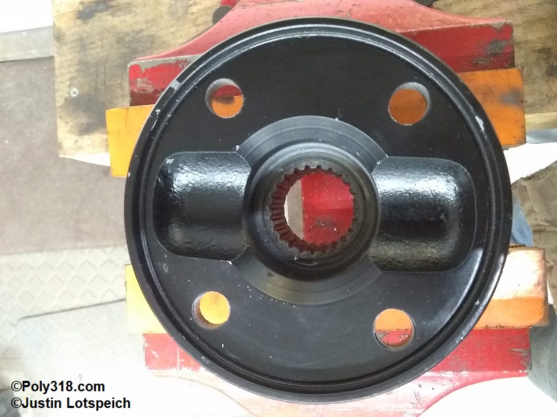
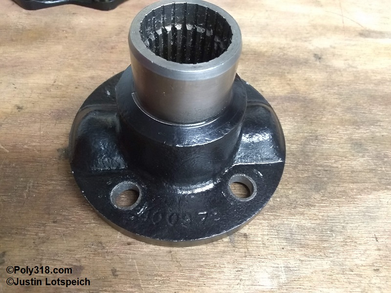
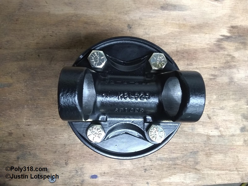
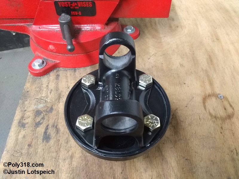
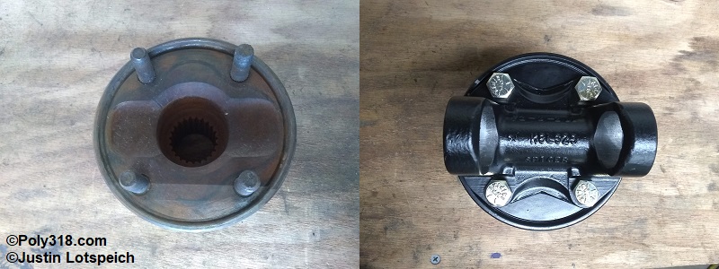
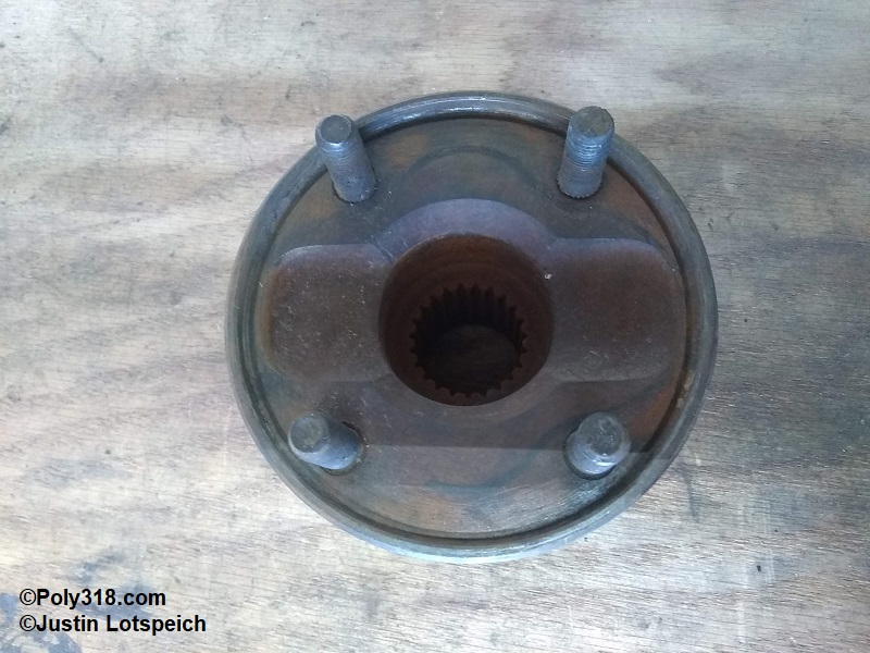
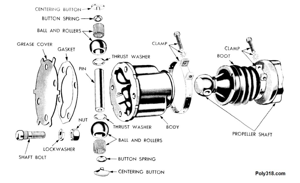
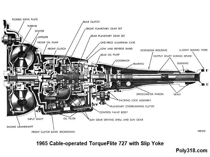
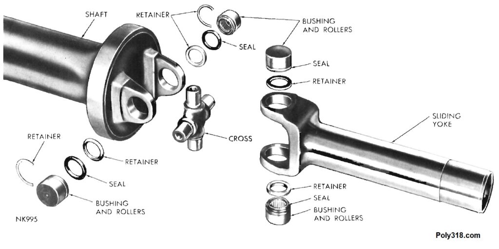
An issue for both stock and performance A, LA, B, and RB Mopars running a 1962 – 1965 TorqueFlite 727 cable-operated transmission is the antiquated ball-and-trunnion drive-shaft design. 1962 – 1964 TorqueFlite transmissions, like their cast-iron TorqueFlite and PowerFlite ancestors, used a splined output shaft with a flange bolted onto the end (Figure 1a). The ball-and-trunnion flange yoke on the drive shaft bolted to this transmission flange (Figure 1b – 1c). Some 1965 TorqueFlites maintained this design, but in 1965 Mopar moved many to a design where a slip yoke slides on the output shaft splines like later 727s (Figure 2a – 2b). As an aside, the 1962 TorqueFlite 727 kept the parking/emergency brake on the transmission and has a different configuration, although I believe my modification below will work on the 1962 brake hub bolt pattern. For stock cars, the ball and trunnion rebuild and replacement parts are becoming difficult and expensive to source along with driveline shops willing to take on the project for those who cannot perform their own work; for performance cars, the ball-and-trunnion coupled with its smaller 2.5″ drive-shaft tube is an inherently weak design compared to slip yokes with universal joints even though they took a beating behind Max Wedge 426 cars when brand new. Since I already needed a new driveshaft after installing a poly 390 stroker and Ford 8.8″ rear axle in my 1956 Dodge coupe, I decided to convert the driveshaft to a slip-yoke but ran into issues piecing together available parts, which I list below.
Converting from Ball and Trunnion to Slip Yoke
There are two options for 1962 – 1965 TorqueFlite cable-operated transmissions to go from ball and trunnion to slip yoke:
Option 1: Swap in a slip-yoke 1965 cable-operated 727 or swap in a 1965 727 cable-operated A/LA/B/RB slip-yoke output shaft and tail housing.
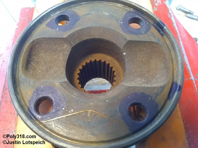
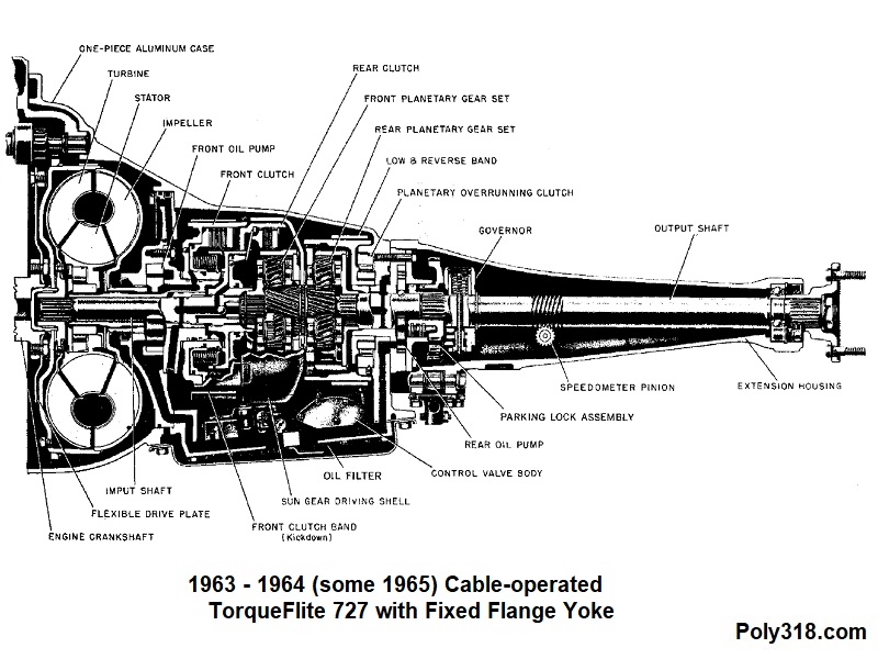
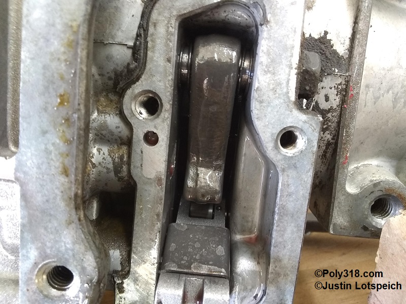
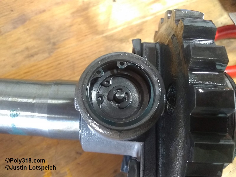
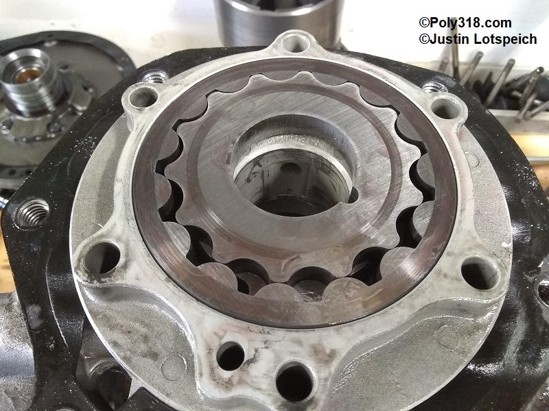
While a relatively straightforward-sounding option, the output shaft and tail housing swap requires taking the transmission completely apart, replacing the output shaft, and installing all the transmission parts with the matching tail housing within tolerances adjusting thrust washers as necessary, which may be out of the realm of mechanical ability and/or affordability for some people. Aside from the cost of new gaskets, possibly new thrust washers, and paying someone for people who don’t do the work themselves, donor slip-yoke 1965 727s are becoming difficult to locate and expensive since they are a one-off year and have been sought after by car modifiers and racer since their invention due to the slip-yoke. A reader might ask, “Why not just swap in any slip-yoke 727 output shaft and tail housing from 1965 – 1989? Why only 1965?” 1963 – 1965 727s include a separate cable-operated parking pawl that works a sprag fastened to the output shaft (Figures 3a and 3b). (1962 727s while cable operated shifting did not have a parking provision on the output shaft). 1962 – 1965 727s also had a rear pump located in the front of the tail housing with provisions for the inner gear and governor on the output shaft (Figure 3c). 1966 – 1989 slip-yoke 727 output shafts and tail housings do not have the necessary provisions for the rear pump and cable-operated parking and, therefore, do not interchange with 1962 – 1965. Even after this output shaft and tail housing swap, a driveline shop would need to build a new drive shaft to replace the ball-and-trunnion unit anyway.
Option 2: Maintain the fixed output shaft flange yoke on the 1963 – 1965 transmission and build a slip-yoke drive shaft using quality parts such as Spicer.
Having a driveline shop add a slip-yoke into a new drive shaft is likely the most affordable and easiest way to delete the ball and trunnion and is just as strong as converting the transmission to a slip-yoke output shaft if using a properly sized midship shaft. The output shaft conversion detailed in Option 1 above requires a new drive shaft anyway, so the slip-yoke addition just means having to pay for only two additional parts: the front flange yoke and the midship shaft, although the cost of the midship shaft is partially offset since it replaces the front tube yoke needed on a slip-yoke transmission.
Building a Slip-yoke Drive Shaft
I have done a great deal of research on the parts necessary for a slip-yoke drive shaft and confirmed the design with my local custom driveline shop that ended up building my drive shaft (photos forthcoming), but some variables come into play with the type of flange on the transmission output shaft and rear end pinion flange that one should confirm independently from the parts I list below since Mopar used different diameter flanges over the years. For example, the 1963 – 1965 A/LA/B/RB 727 output flange I’m using in my 1956 Dodge coupe has a 3.25″ bolt circle and a 3-15/16″ diameter outer curb that originally kept the ball-and-trunnion flange captured and centered since neither the output flange nor the ball-and-trunnion flange has a male/female pilot. Currently available flange yokes (as of 2021) limit our options to the 1310 u-joint series, which are plenty strong for the vast majority of street-strip cars. According to Spicer, the cold-forged solid 5-1310X u-joint (no external greasing provision) is rated for 800 lb.ft. continuous load (like wide open throttle down the drag strip) and 1,600 lb.ft. of short-term load (like launching off the starting line). The 5-178X with its grease galleries is rated at 400 lb.ft. continuous, 800 lb.ft. short term loads. I’ve searched high and low for a 1330 or 1350 option to no avail, so if anyone reading this article knows of a 1330 or 1350 option that will fit or nearly fit the above output flange size parameters, please shoot me an email so I can update options here. At least for my build, I’ll never come close to 800 lb.ft. continuous or short-term, so I’m not worried about needing a 1330 or 1350 even though I use 1350 for the rear components for added security since they don’t really cost more. Of note, I think the 904s (V8 and S6) with fixed output shaft flange may have used a smaller flange on their smaller output shafts since I’ve run across people online discussing a 2-7/8″ bolt circle flange, but I haven’t been able to confirm for myself since I don’t have a 904 output flange.
For factory Mopar conversions for those interested in the comparison, the 1310 is on a similar strength level as a 7260 (“small joint”), and the 1330 is on the same strength level as a 7290 (“big joint”). The 1350 is stronger than the 1310/7260/1330/7290 at 1,200 continuous and 2,200 short-term lb.ft. load.
The last consideration is drive-shaft tube diameter and gauge. Many ball-and-trunnion Mopars used a 2.5″ tube, which is worth upgrading to 3″ x .083″ wall tube when having a new drive shaft built. If one desires a 2.5″ tube, flanges and midship shafts are available.
In the build sheet below, I include the rear flange yoke to go from a 1350 u-joint to a Ford 8.8″ rear end I am using in the 1956 Dodge, but rear ends such as the Mopar 8.75″ and Ford 9″ do not require an additional flange yoke since the u-joint secures to the pinion flange.
Parts List from Transmission to Rear End (in progress with build photos to come):
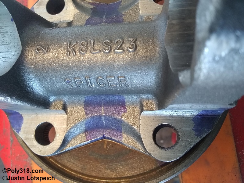
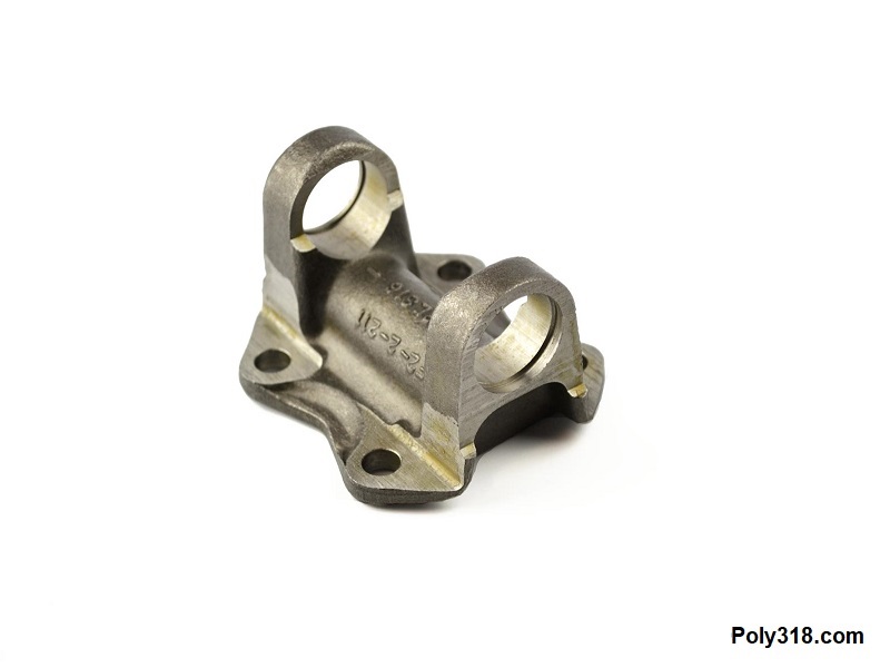
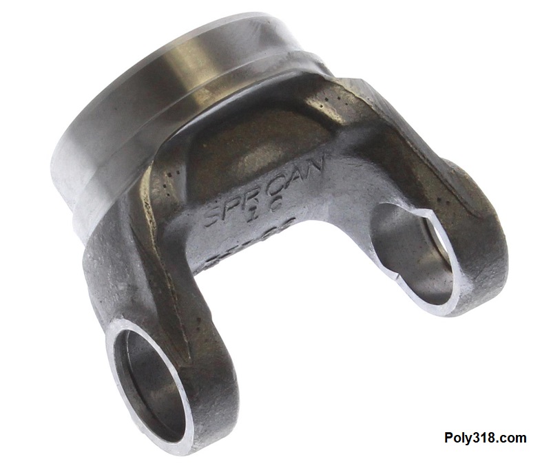
- Front Flange Yoke (to bolt onto the transmission output flange): Spicer 2-2-459 (1310 series, 3.125″ bolt circle, 4 bolt holes at .375″ diameter, 3.875″ outside circle, Figure 6). This is the only suitable, available flange yoke I can find, and I had to modify both the flange yoke and transmission output flange to make the setup work, which I detail in the next section after going through the parts list. Note that the old Spicer 2-2-1769 in their catalog that is a nearly perfect fit is long since out of production with no reliable source. There is also a 2-2-389 flange yoke available with a 3.125″ bolt circle, but the 2-2-459 flange yoke is a better candidate.
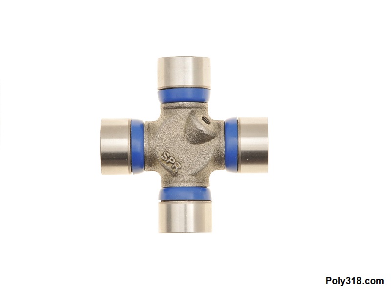
- Front Universal Joint: Spicer 5-1310X (1310 series, cold-forged, no grease galleries, Figure 7)
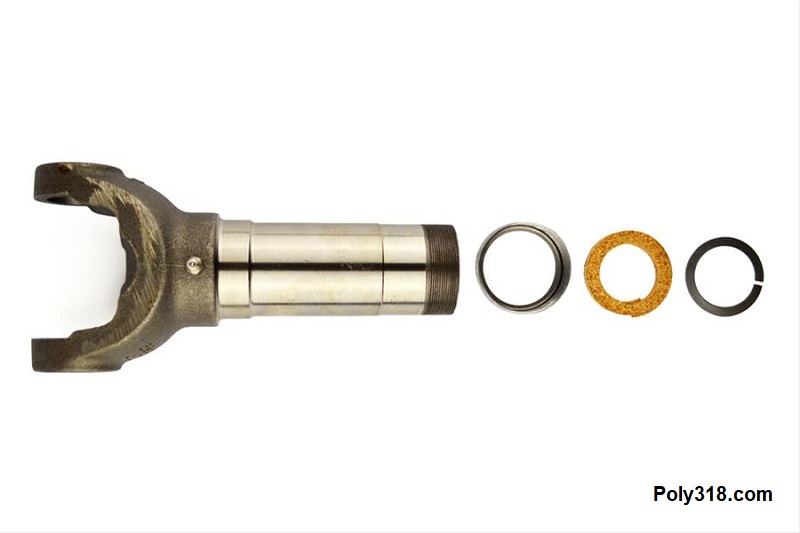
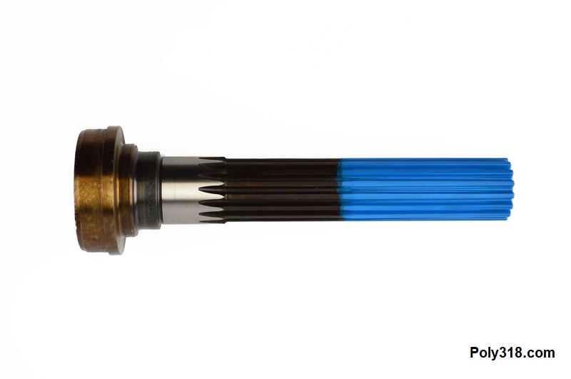
- Slip Yoke: Spicer 2-3-6061KX (1310 series, 1.5″ diameter x 16 female spline, 6.875″ from center joint to end, Figure 8)
- Midship Shaft: Spicer 3-53-1531 (1.5″ diameter x 16 male spline, 6.58″ long splines, for 3″ x .083 tube, Figure 9)
- Tube: 3″ x .083″ (long enough with the vehicle level on the ground at neutral rest under its own weight to allow the midship shaft to slide into the slip yoke leaving 1″ of free space for lateral movement before bottoming out)
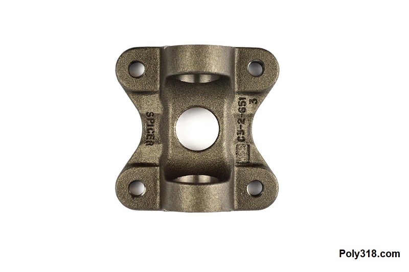
- Rear Tube Yoke: Spicer 3-28-57 (1350 series, for 3″ x .083″ tube, Figure 10)
- Note: The rear tube yoke may require a different u-joint series depending on the rear end pinion flange. For example, if the pinion flange requires a 7290 u-joint, use a 7290 tube yoke.
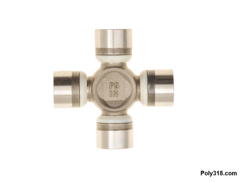
- Rear Universal Joint: Spicer 5-178X (1350 series, greasable, Figure 11)
- Rear Flange Yoke: Spicer 3-2-1619 (1350 series, 4.25″ bolt center, 4 bolts holes at .472″ diameter, 2″ diameter pilot, Figure 12)
- Note: This flange is only necessary when connecting the drive shaft to a version of the Ford 8.8″ with a flat pinion flange.
Modifying the Transmission Output Flange and Front Drive Shaft Flange Yoke
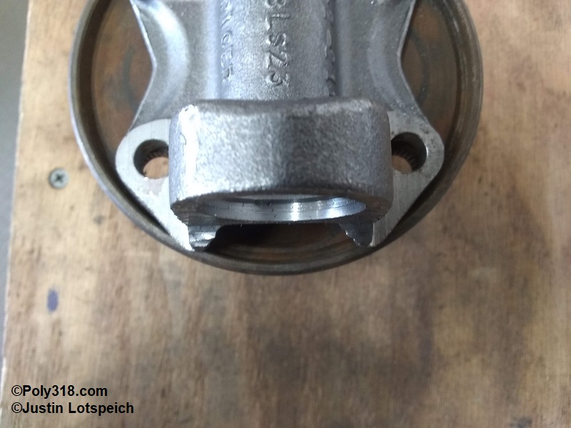
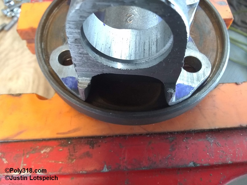
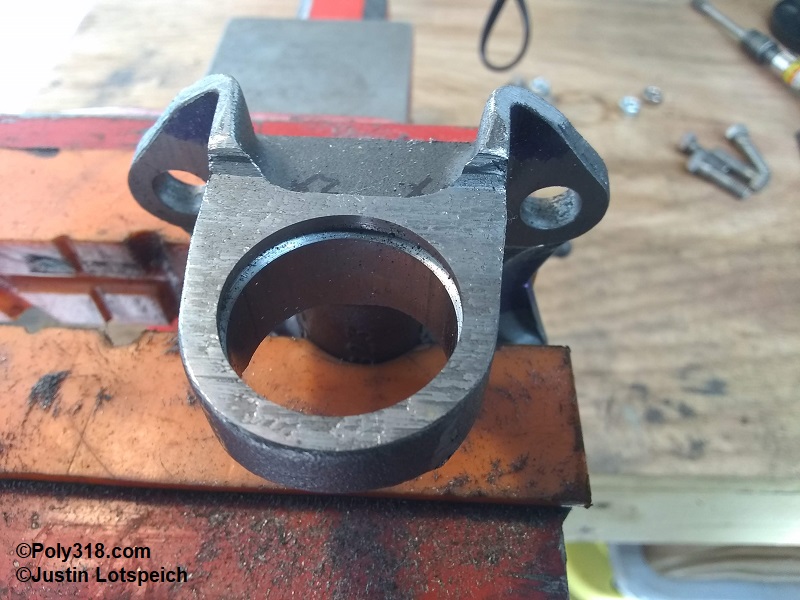
There are three issues with the output flange and Spicer 2-2-459 flange yoke: first, the output flange has a 3.25″ bolt circle when the Spicer flange has a 3.125″ bolt circle. Second, the output flange has an well diameter of 3.94″ when the Spicer flange has an outside circle of 4.10″ despite being advertised as a 3.875″ (Figure 13). Third, the Spicer flange has a male pilot on the backside that doesn’t allow the flange to rest flat on the output flange (Figure 14). To make the two flanges work, the stud holes need to be elongated, the Spricer flange perimeter needs to be carefully fitted into the output flange well, and the pilot on the backside of the Spicer flange needs to be machined off.
As soon as I received the Spicer flange, I realized I would not be able to elongate the stud holes outward enough to match the output flange’s bolt circle since there would be little material left around the holes to where the material could crack and tear away under a high-torque situation like launching at the drag strip with slicks. The only solution was to press out the output flange studs, elongate the holes inward to match the Spicer’s smaller bolt circle, and use bolts instead of studs. This solution wouldn’t have any negative impact since the Spicer flange would be centered and pinned in place inside the output flange well.
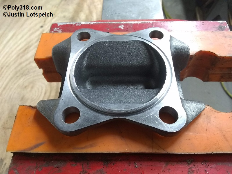
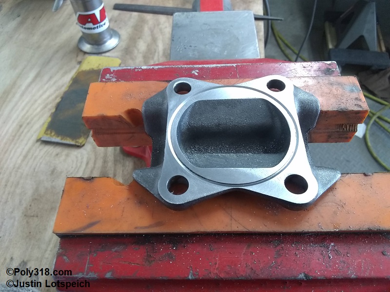
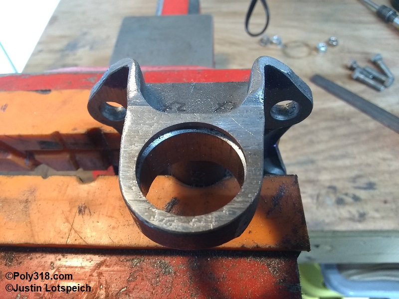
I addressed the pilot on the backside since I needed to remove it before I could start machining the Spicer flange to fit inside the output flange well. I used the angle grinder with a 60-grit sanding disc to knock down most of the pilot, used a file to bring the pilot flush with the rest of the flange, and then used a machinist’s straight edge with sandpaper and oil to sand the flange until I had an even sanding pattern across the surface (Figure 15). I wish I had a mill, which would have made the process much quicker.
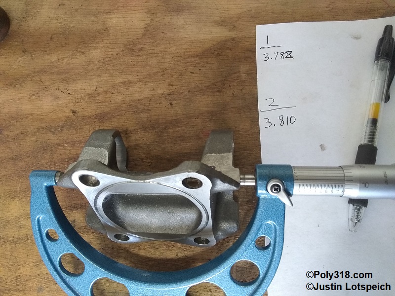
Before I began modifying the Spicer flange, I took some measurements with a couple mics to gauge how I should go about the modifications. I found that the outside of the towers were not cast perfectly symmetrical, so using a lathe wouldn’t machine things on center, and the small lathe I have wouldn’t expand enough to securing clamp the flange anyway. I decided to modify the flange using an angle grinder to knock down the bulk and then a hand file to fine tune the fit. While measuring, I also found that one size of the flange was slightly wider by .028″ than the other (Figure 16). I scribed a control line on both sides of the flange, miked from the widest part of the tower to that benchmark, and filed the long side evenly to where both sides matched.
I pressed the studs out of the output flange and centered the Spicer flange over the output flange. Using a pair of vernier calipers, I marked the Spricer flange where I would take down the bulk of the material before fine tuning the finish with a file (Figure 17). After I sanded to that line and carefully filed the while repeatedly checking with the vernier calipers to ensure I was staying centered on my control lines until the Spicer flange sat down snugly into the output flange well with no sideways movement (Figure 18). Precision down to the thousandth of an inch is key here since any offset will cause the driveshaft to rotate in an ellipse that will create vibrations. The driveshaft builder can address some offset with balancing, but my goal is to be dead on.
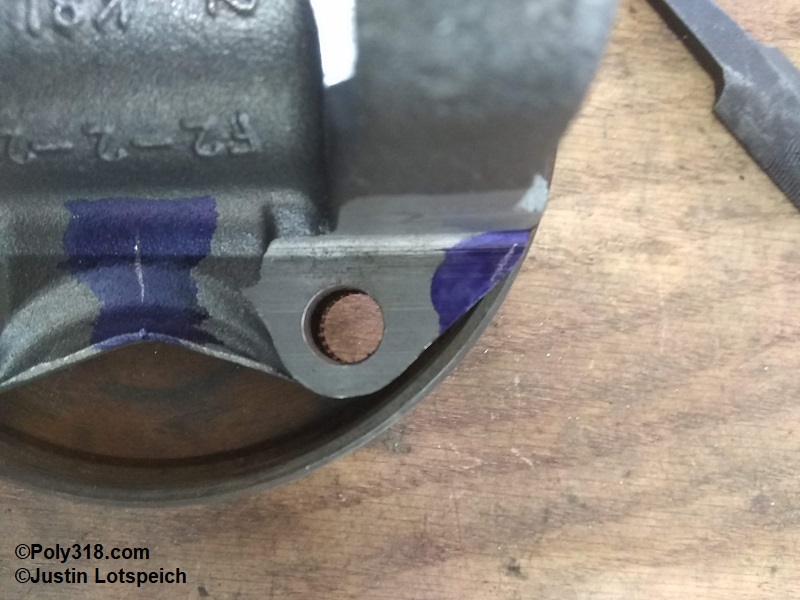
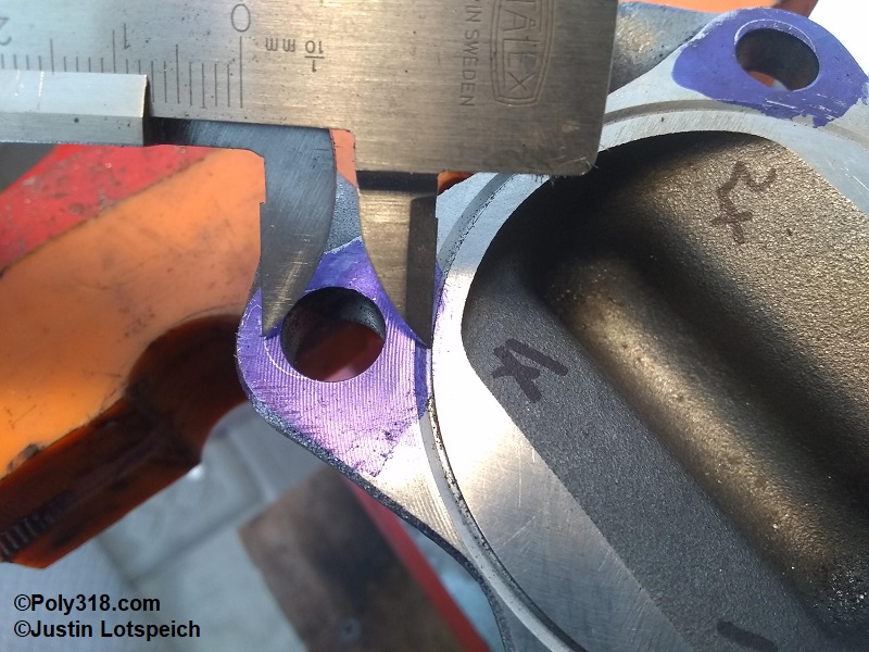
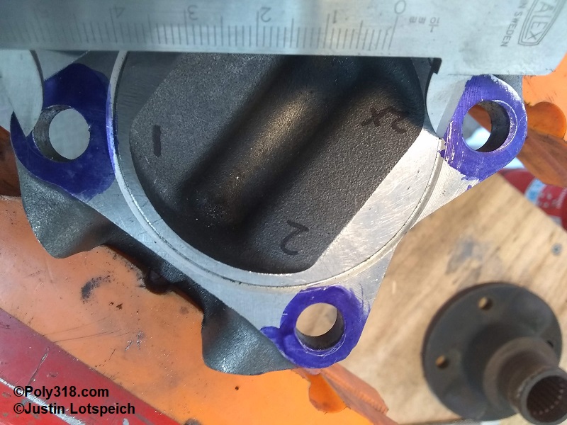
The next problem to address was the bolt holes. To confirm one last time that the Spicer flange was centered in the output flange well, I secured the Spicer flange with the backside facing up in a vice, set the output flange down on it, and scribed the output flange holes onto the backside of the Spicer flange. Using vernier calipers, I check the distance from the scribed line to the closest pilot wall (Figure 19) and then checked in an “X” pattern from the scribed line to the farthest diagonal pilot wall, which proved the Spicer flange was centered (Figures 20).
Figure 21 shows how the output flange has a larger bolt circle than the Spicer flange. I scribed the Spicer flange bolt holes onto the output flange (Figure 22) and used a carbide bit in a pneumatic die grinder to carefully elongate the output flange holes inward just enough for 3/8″ bolts to very snugly slid through.
With the modifications completed, I sanded and filed the sharp edges from my modifications and that the factory left on the Spicer flange since they present stress risers where cracks are more likely to form (Figures 23 – 25). After wire-wheeling the flanges and cleaning off residual oil, I finished the flanges with primer and chassis black paint (Figures 25 – 28).