Engine Lifter Inspection,
Blueprinting, Disassembly,
Cleaning, Assembly
Introduction
An often-overlooked process during engine building or changing a camshaft and lifters is inspecting, blueprinting, disassembling, and cleaning lifters. As part of my engine builder’s series working on an A-block poly 390 stroker, I cover the process in this article. It is wise to never trust any factory assembled precision internal engine part like lifters and to instead confirm tolerances and clean them prior to installation. One expects that manufacturers of precision engine components maintain the highest standards of machining and assembly, particularly with USA-made parts, but examples in this video show that standards can be low.
From about 2000 – 2020, there had been many reports from machinists, engine builders, and users of flat-tappet mechanical and hydraulic lifters failing and flattening camshafts. While some issues stemmed from problems with lifter foot hardness, many of the issues were likely from people using incorrect oil with inadequate ZDDP, incorrect valve lash/preload, problematic camshaft/lifter break-in procedures, or a combination of these builder/user errors. Inspecting, blueprinting, and cleaning lifters is an easy way to remove one more variable from potential lifter, camshaft, bearing, and journal damage and failure. While I use a hydraulic flat-tappet lifter in this video, much of the procedure applies to mechanical flat-tappet and roller lifters that can be disassembled.
At the end of this article, I provide a video where I review five different flat-tappet lifters that are eye-opening since a USA cast, machined, and assembled lifter ends up being of terrible quality compared to a likely imported lifter. Quality lifters may be purchased through reputable retailers such as Summit Racing, Jegs, and Rock Auto. I highly recommend never purchasing anything from Hughes Engines, which I review in another video.
Lifter Quality and Damage
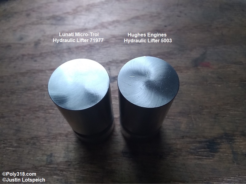
Lifters come in different levels of quality, demonstrated here by comparing the Lunati Micro-Trol 71977 hydraulic lifters I work on in this article to a set of Hughes Engines 5003 hydraulic lifters I received for an engine build (Figure 1a). According to Lunati’s technical support and Top Line Automotive who makes Hylift Johnson lifter bodies, both these Lunati and Hughes Engines models use the USA-cast and machined Hylift Johnson body. The Lunati foot has a clean, uniform finish like quality lifters should with no gouges or other blemishes. A machinist’s pick drawn across the foot and around the edge does not catch. The exterior of the body is smooth with no pitting, gouges, or nicks.
In stark contrast, the Hughes foot has a terrible finish with deep gouges that a pick easily catches and an extremely problematic nicked edge (top center) that protrudes to where the body is outside diameter tolerance and drags when placed in a lifter bore. If the lifters look like these Hughes lifters out of the box, do not bother further inspection and cleaning since they should be resurfaced or discarded.
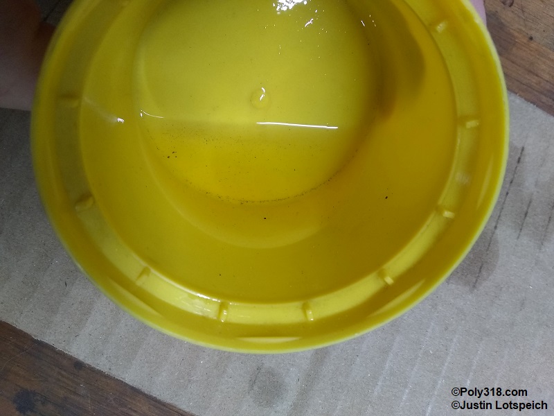
Trusting that a manufacturer used high standards of cleanliness when assembling lifters is an unnecessary risk. I disassembled three of the Hughes 5003 lifters pouring the assembly oil into a clean container (Figure 1b). There were visible contaminants in the internal assembly shown in the photo. This debris from only three lifters would either remain in the lifters where it could wear the components or would be flushed into the engine’s oiling system where it could cause damage to bearings and journals before being caught in the pan or oil filter. If I had not disassembled the lifters, I would have never known.
In contrast, after disassembling all sixteen Lunati lifters I found no debris in the assembly oil.
Lifter Inspection
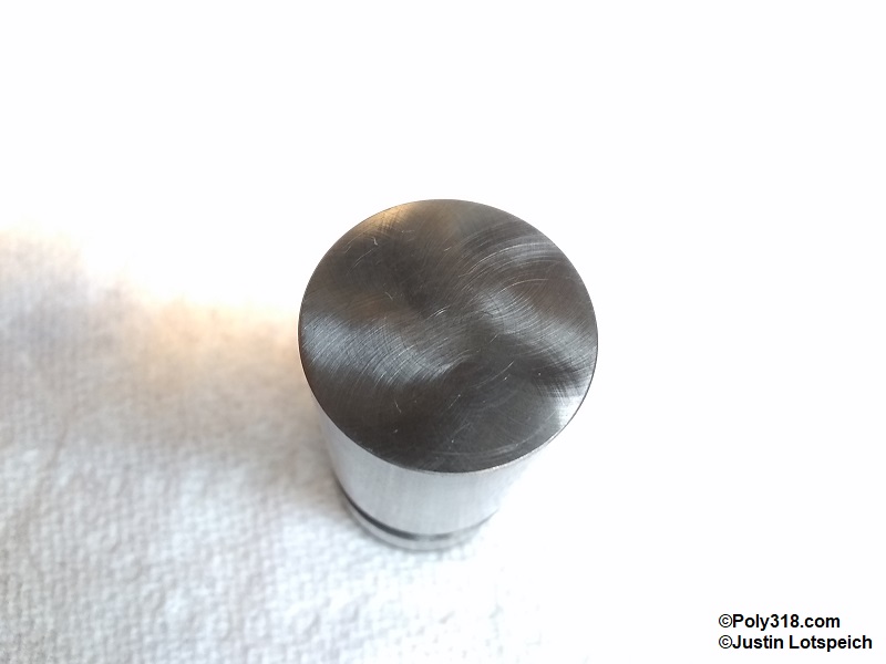
To begin the inspection, look at the foot for a uniform, smooth finish free of gouges and nicks (Figure 2a). The machined pattern can vary from a flower, machine-turned, to a swirl. Light scuff marks often in rings from sliding along the assembly conveyor equipment are acceptable, but a mechanic’s pick should not catch when drawn across the foot. There should be a uniform, smooth chamfer on the edge free of nicks and raised material. Any raised material on the edge chamfer may be smoothed with 600-grit emery cloth wet with WD-40, but the sanding should be even around the entire perimeter to not sand in a flat spot. Do not sand the foot surface when easing the chamfer since it will modify the crown, which I discuss in a following section.
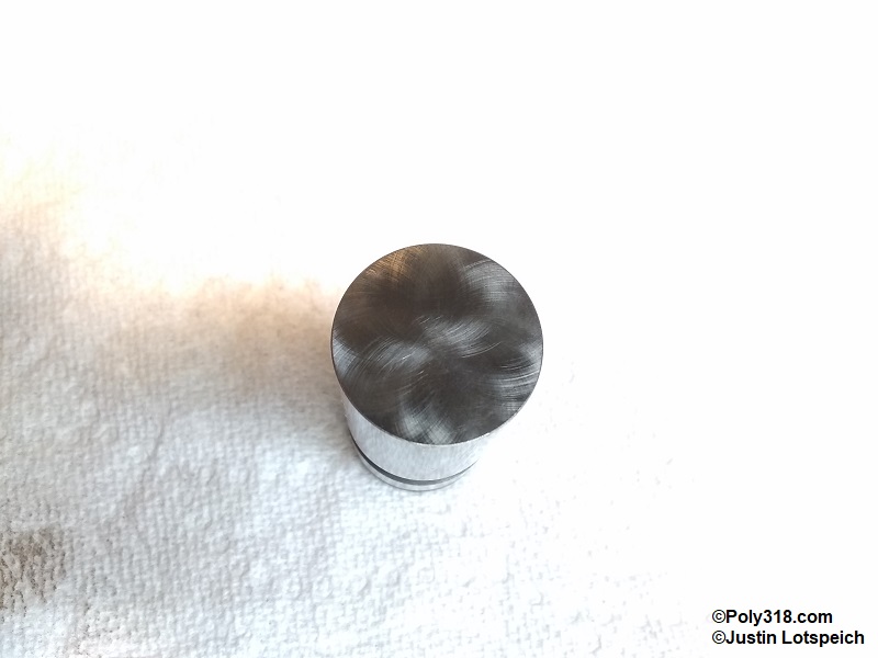
Figure 2b shows a Howards lifter I have with a quality swirl pattern finish just as a comparison to the Lunati’s flower pattern. Notice the light ring scuff mark around the outside of the foot, which is from the lifter moving down the assembly line. These types of scuff marks are normal and are not dug into the metal. Do not attempt to remove them using emery cloth since sanding will damage the crown.
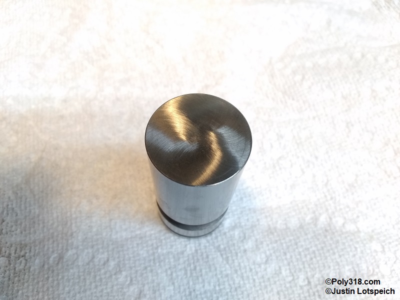
Figure 2c shows one of the Lunati lifters in the set with normal light ring scuff marks from moving down the assembly line. A mechanic’s pick does not catch on them, and they will not create any issue when run in an engine.
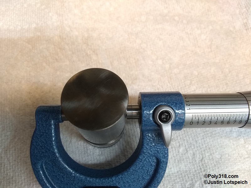
After inspecting the foot, use a micrometer to measure the diameter at the top, center, and bottom of the body, which should all match to show an evenly round lifter (Figure 2d). Compare the measurement to the engine manual specification.
All sixteen of these lifters measured 0.9040″ within tolerance of 0.9040″ – 0.9045″. Lifters that fall outside tolerance should be discarded.
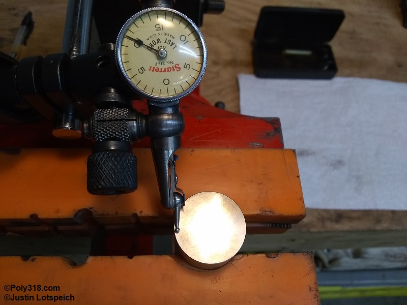
The next step checks the crown of the foot (check the engine manual since some engines like Buick nail heads have little to no crown). Most flat-tappet lifters want between 0.002″ – 0.003″ of crown height compared to the perimeter of the foot. Most camshaft lobes have between 0.0007″ – 0.002″ of taper across the face. The lifter crown and cam lobe taper work together to make the connection just off center of the foot and lobe to constantly spin the lifter. Secure the lifter and set up a dial test indicator in the middle of the foot touching the surface (Figure 2e). Zero out the gauge.
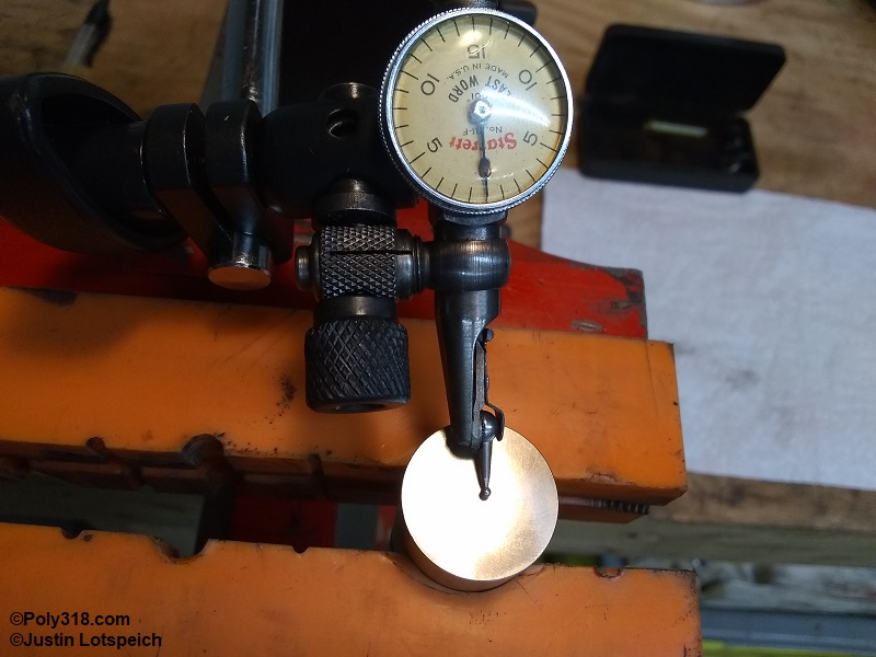
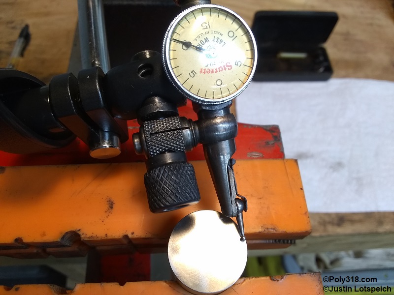
Gently swing the base arm to the side until the indicator rests just before the chamfered edge (Figure 2f). Write down the measurement, which is the crown height and in the case of these lifters a hair under 0.0020″. All lifters from this set measured the same.
Gently swing the base arm to the other side until the indicator rests just before the chamfered edge (Figure 2g). Write down the measurement, which for this set matched the other side. If the measurements do not match, reset the gauge to zero in the center and recheck the perimeters. If the second measurements don’t match, either have the lifter resurfaced or discard; using a lifter with an uneven crown may result in the lifter catching on the camshaft lobe where it may stop spinning and will flatten.
Lifter Disassembly
It is crucial to keep all components of the individual lifter together during disassembly and cleaning because the factory uses different minutely sized internal components for each lifter body to maintain specifications. Do not simply disassemble all the lifters and throw the parts into the same container; mixing up components will result in inconsistent lifter performance across the set that will result in uneven cylinder performance.
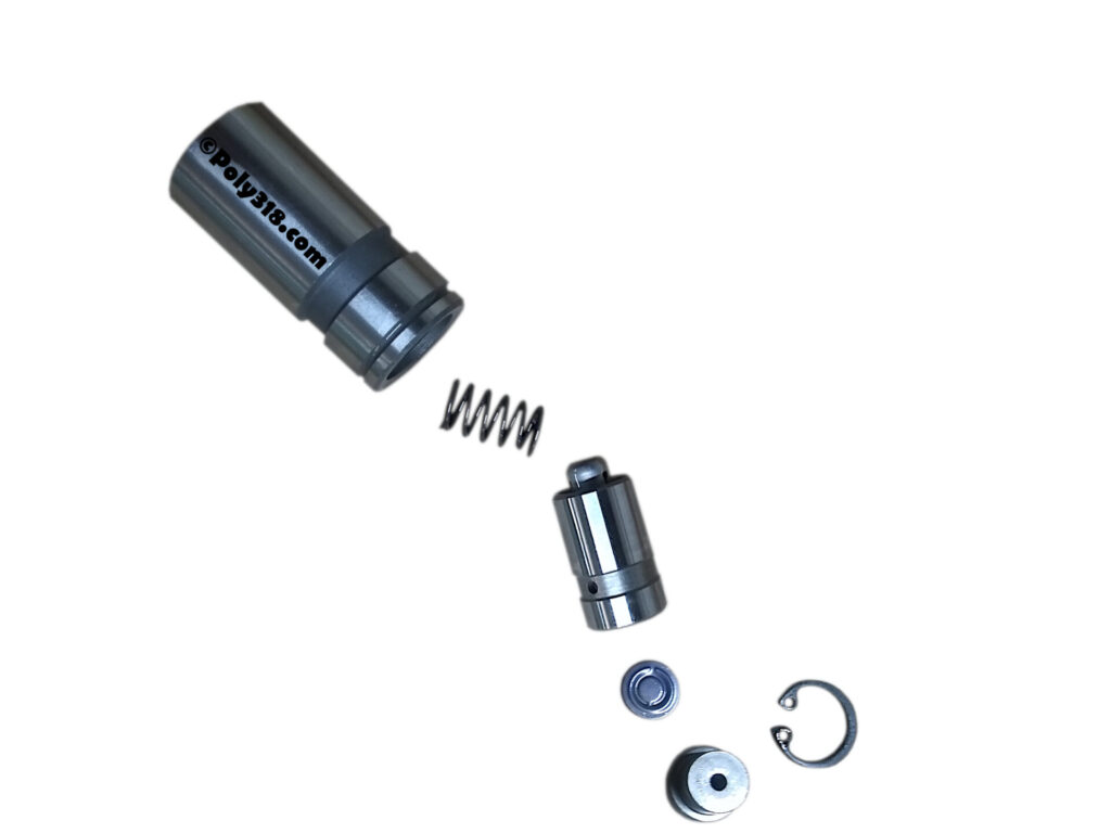
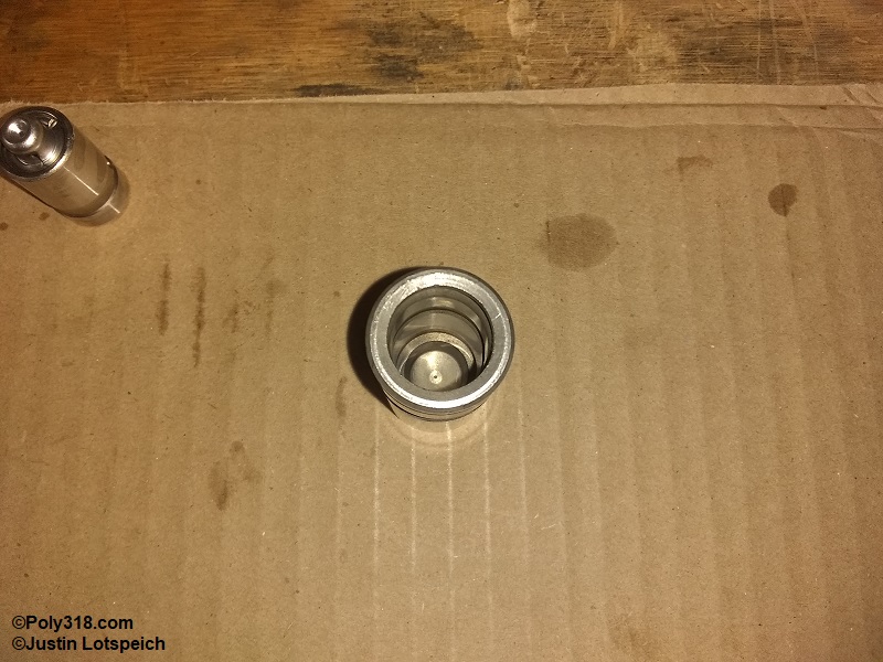
Secure the lifter in a soft-jaw bench vise. These Lunati lifters use a snap-ring, but other retainers include wire clips and sheet-metal inserts (Figure 3a). Using snap-ring pliers or a small screwdriver, remove the retainer. Note that sheet-metal inserts do well in not allowing the lifter to come apart but are a cheap alternative to snap-rings. The sheet-metal retainer must be bent up in the middle to remove it requiring a new retainer for assembly, whereas the snap-ring or wire clips may be reused.
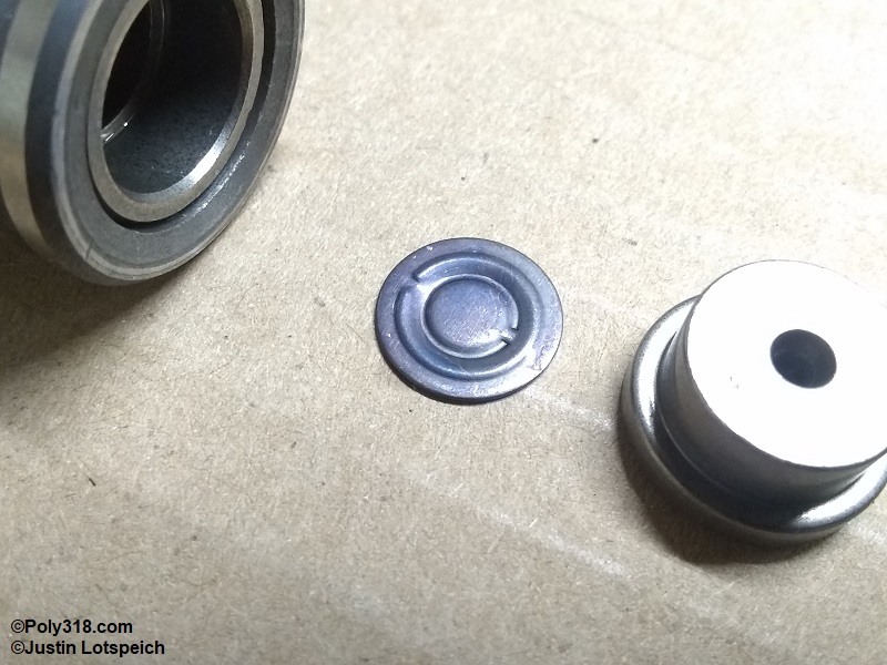
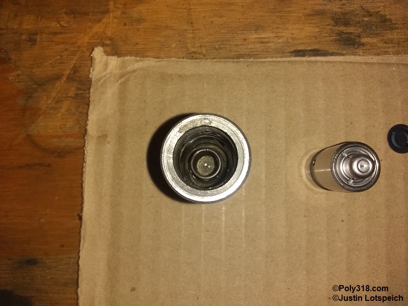
Using a magnet, very slowly lift the plunger cup out of the body until the metering valve is visible (Figure 3b). Stop and inspect the metering valve to see if it has a unique shape that has an “up” side and a “down” side. If the valve flips before the position can be confirmed, plan on carefully checking another lifter during the next disassembly.
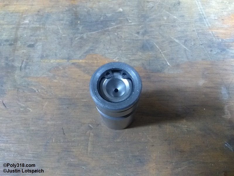
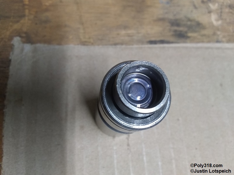
For these Lunati lifters, the metering valve has a large-diameter bead and a small-diameter bead with ridges on opposite sides of the valve (Figure 3c). The ridge of the large-diameter bead faces up, like in the image, toward the plunger cup. While I am not a lifter engineer and do not know if the valve must be placed in this position to function properly, all sixteen valves were in this position and will be reinstalled in the same position. Many valves are flat discs and can be installed with either side up.
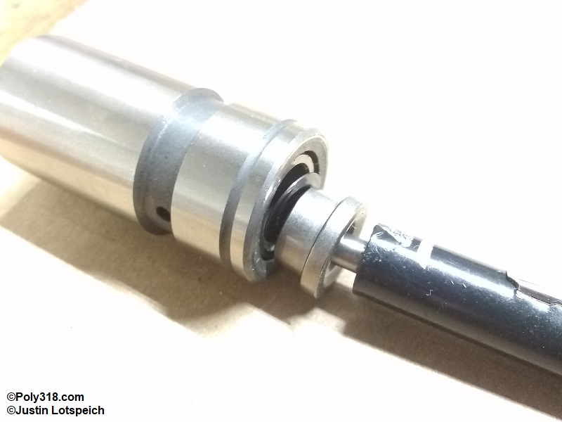
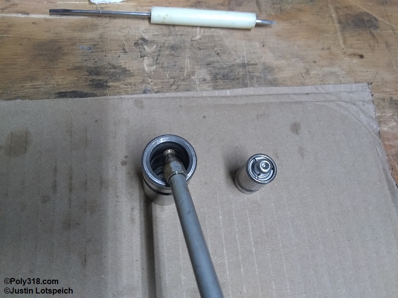
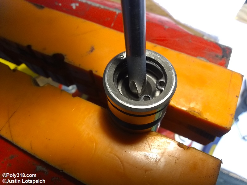
The plunger will often be stuck firmly in the body due to suction and will not drop out when overturned. Sometimes, the plunger will lift out by jambing a finger into the plunger and lifting up. However, I almost always have to use a tool. I slide two short pieces of 1/4″ vacuum hose over snap-ring pliers to protect the plunger’s bore wall, insert the pliers into the bore, tighten the pliers against the wall, and lift out the plunger (Figure 3d). Invert the lifter body over a container to pour out the assembly fluid and the plunger spring.
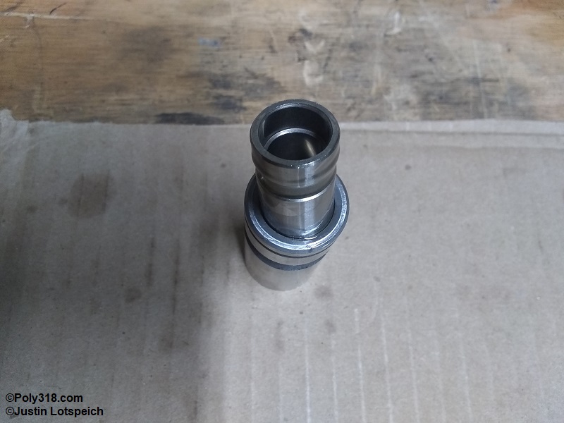
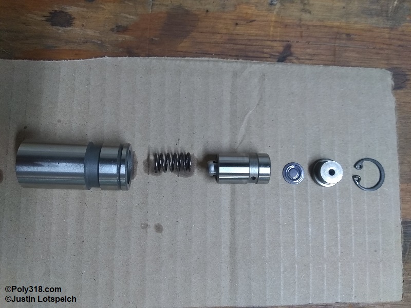
Figure 3e shows the disassembled lifter ready for cleaning including the body, plunger spring, plunger, metering valve, plunger cup, and retainer snap-ring. These parts must be kept together as a unit for each lifter and should not be mixed up with other lifter components.
Lifter Cleaning
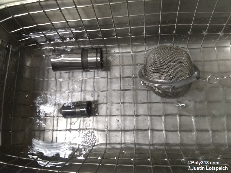
As with most engine internal components, I use a heated ultrasonic cleaner with new mineral spirits heated to 90°F (Figure 4a). This method takes only three minutes per lifter to fully clean the parts. After removing the parts, set them on a few clean paper towels to drain, and then blow them off well with compressed air. It is okay if there is solvent residue on the components. Set the components aside at the clean assembly area.
Closely inspect the body bore for any burrs or raised edges that may cause the plunger to hang up (Figure 4b). Inspect the plunger exterior for similar. If any burrs or raised edges exist, knock them down with 600-grit emery cloth wet with WD-40 and clean the part again. These Lunati lifters had no issues.
Lifter Assembly
The assembly area should be wiped of debris and blown off well with compressed air. Lay out the parts in an assembly line, and obtain motor oil or WD-40 for assembly oil. Place a few drops of oil down the side of the body bore. Do not fill the bore full of oil but just enough to lubricate the plunger (Figure 5a). Drop in the plunger spring, and ensure it is centered down in its well (Figure 5b).
- Place a few drops of assembly oil on the outside of the plunger.
- Gently drop the plunger into the body, and spin it a couple rotations to spread the oil and to ensure the plunger seats on the spring.
- Drop the metering valve into the plunger being careful it is positioned with the correct side up. In this case, the large diameter ridge faces up.
- Place a single drop of oil on top of the metering valve.
- Drop the plunger cup atop the metering valve (Figure 5c).
- Secure the lifter in a clean, soft-jaw bench vise.
- Slide the retainer, in this case a snap-ring, over a clean Phillips screwdriver.
- Press down on the plunger cup enough to clear the retainer groove, and install the retainer. This process may require using a small flathead screwdriver to chase the retainer around into place. The retainer should be an extremely tight fit.
- Once the retainer is secured in place, compress the plunger a couple times. The plunger should smoothly move up and down with strong resistance from the spring. If the plunger sticks or does not return up against the retainer, there is an issue requiring diagnosis (Figure 5d). Look for any metal shavings from the retainer and blow off as necessary.
- If the plunger operates properly, remove the lifter, wipe off the body, and box or bag it until installation into the engine. Do not soak the lifter in oil or bench prime it. The assembly oil protects the internal components until the oil system is primed prior to startup.
Conclusion
Inspecting, blueprinting, cleaning, and assembling lifters is a straightforward and important part of engine building or changing a camshaft and lifters. Without completing the process, one cannot know for certain that the lifters are within tolerance, free of issues, and clean. I produced a video with the above process, and in another video I review five different lifter brands that might be worth viewing: