Classic Dodge, Plymouth, Chrysler, & DeSoto Brake System Upgrades
Introduction
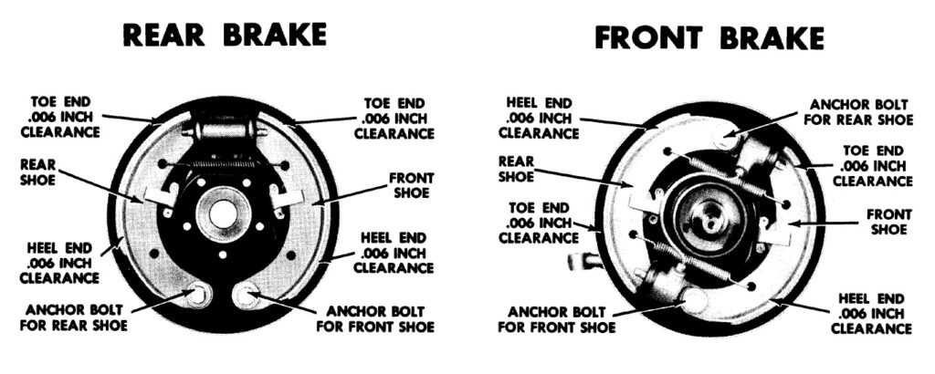
Without going into detail covering all the pitfalls of the design, the factory 1955 – 1956 Dodge, Plymouth, Chrysler, DeSoto along with other Forward Look hydraulic brake systems are antiquated and inferior to modern alternatives. For those putting around town, a properly working and adjusted factory system works just fine, although the single-reservoir master cylinder lacks the safety feature of a dual-reservoir and the cars lack the safety of a proportioning valve; for anyone accustomed to any drag or road-course racing or curvy highway driving with higher speeds and frequency of braking, the factory system very quickly heats up, fades, and stops gripping no matter how hard you are standing on the brake pedal. I wrote this article in the context that I replaced my 1956 Dodge coupe’s factory rear end with a Ford Explorer 8.8″ disc-brake 3:73:1 posi assembly and the front brakes with large Dodge Dakota disc brakes when I clipped the car with Dakota independent front suspension. With four-wheel disc brakes, anticipated 1/4 mile trap speeds of 110 MPH with the 390 stroker poly A-block, and driving in the Rocky Mountains, it was only logical to tear out the factory master cylinder, hard lines, and hoses and design and fabricate a completely new system. While I detail the entire system design and fabrication in this article, the section regarding the master cylinder and proportioning valve is applicable to those wanting to upgrade the master cylinder to a dual-reservoir configuration for a fail-safe or when converting the front brakes to disc.
Dual Reservoir Master Cylinder Upgrade Options
Fortunately, after doing some good old catalog searching and looking up available specs and bolt-pattern dimensions for master cylinders, we have two options for classic Mopars including 1955 – 1956. The first consideration when selecting a master cylinder is the type of brakes on the car; the next consideration is the aesthetic style of the master cylinder.
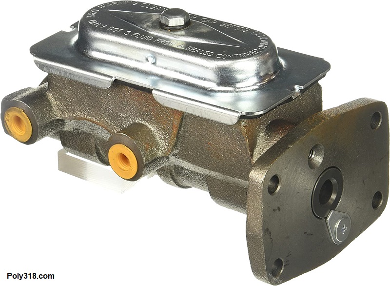
- Cars with four wheel drum or disc brakes: Best supported by a even dual-reservoir master that supplies the same volume of fluid to both the front and rear circuits since both circuits will use similar amounts of fluid over time when the wheel cylinders or calipers require additional fluid as the brake shoes/drums or pads/rotors wear. An attractive option that bolts right up to the classic Mopar firewall and works with at least the 1955 – 1956 factory pedal pushrod is a Raybestos MC36221 (Figure 1a) used on four wheel drum brake 1967 – 1970 Mopars (use a 1969 Dodge Coronet RB440 as a parts search for other brands). This master has a period-correct bolt-on cap, takes a 9/16″-20 male flare nut for the rear brake line and a 1/2″-20 male flare nut for the front brake line, and has a 1.00″ piston bore. This master has 10 psi residual valves in both the front and rear circuits that need removing for disc brake circuits, which I discuss in the “residual valve” section below. Since my car has four wheel disc brakes and I wanted a more 1960’s period look, I went with this master.
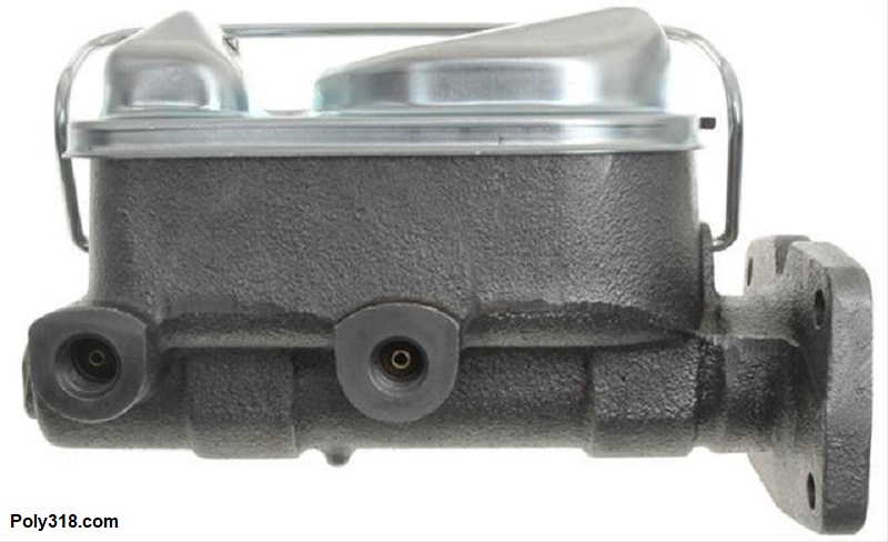
- Front disc and rear drum: Best supported by an uneven dual-reservoir master that has a larger front brake fluid capacity than the rear (note that while counterintuitive, the rear reservoir is the larger reservoir piped to the front brakes). The reasoning here is that as the front brake pads and rotors wear, more fluid is pulled from the master to fill the growing caliper piston bore compared to the volume needed to fill the piston bore of the drum brake wheel cylinders. Rather than elongate the entire master body, Mopar simply offset the wall separating the two reservoirs. An even master cylinder like above can be used on a front disc/rear drum system, but it requires the owner to more frequently check the reservoir fluid level as the brake pads and rotors wear to ensure the front circuit doesn’t run low enough to start sucking air. An option that bolts right up to classic Mopars firewalls and works with at least the 1955 – 1956 factory pedal pushrod is a Raybestos MC36307 (Figure 1b) used on front disc/rear drum 1971 – 1974 Mopars (use a 1974 Dodge Coronet RB440 as a search for other brands). This master says 1970’s much more than the above version, but it’s more compact and attractive than the 1970’s Corvette-style master used in most universal kits. It takes a 9/16″-20 male flare nut for the rear brake line and a 1/2″-20 male flare nut for the front brake line. It has a piston bore of 1.031″ and will have a very slightly harder pedal feel than the above even-reservoir master. This master has no residual valve in the front circuit and a 10 psi residual valve in the rear circuit (see the “residual valve” section below for more details).
Proportioning, Residual, Metering, Pressure Differential, and Combination Valves
There’s plenty of confusion out there regarding proportioning, residual, metering, pressure differential, and combination valves in a brake system that I hope to clear up quickly for our discussion:
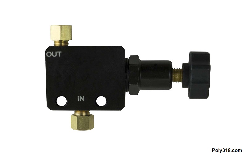
Proportioning Valve: The purpose of a proportioning valve is to regulate the amount–as in the proportion–of pressure applied to the front and rear brake circuits only under panic stops. These valves can be incorporated into a combination valve or can be in-line and adjustable (Figure 2a). A lot of people online, and I’ve even read it in magazines, mistakenly think this valve regulates pressure all the time, which isn’t true. When the brake pedal is mashed quickly and hard, the spiking line pressure to the rear circuit trips the proportioning valve that in turn decreases the line pressure to the rear circuit to keep the rear wheels rolling rather than locking up and potentially causing the rear end to fishtail or spin out. A proportioning valve is a wise safety device to install on four wheel drum, four wheel disc, or disc front/drum rear systems to assist with emergency stops.
Residual Valve: A residual valve is a type of shutoff valve that locks a preset amount of pressure into the circuit downstream the valve. The valve is either incorporated into the master cylinder, incorporated into the combination valve, or added in-line (Figure 2b). As the braking force is removed from the master cylinder, the pressurized fluid in the lines/wheel cylinders/calipers bleeds off into the master cylinder reservoir(s). Without a residual valve, the line pressure goes to 0 psi, and in some cases the fluid in the system can drain back into the master via gravity. The residual valve allows pressure to bleed off down to a preset amount at which point the valve shuts, locking in some pressure.
There’s a lot of confusion out there about whether a system requires residual valves. The fact is that for all-wheel disc brake systems with the master cylinder mounted at an elevation above all the calipers, no residual valve is necessary since the fluid will not gravity drain back into the master; for systems with either all-wheel disc or front disc/rear drum when the master cylinder is mounted at an elevation below any caliper–common on some pre-1960 pickup trucks and cars–the disc brake circuit(s) require a 2 psi residual valve. The 2 psi is not enough to cause the brake pads to drag but is enough to stop the fluid from gravity draining back into the master cylinder, which is the only reason to use a 2 psi residual valve on a disc brake circuit. It won’t hurt anything to run a 2 psi residual valve on a disc brake circuit when the master is higher in elevation than the calipers, but it’s unnecessary.
The rule is easier to remember for drum brakes: all drum brake circuits requires a 10 psi residual valve no matter at what elevation the master cylinder is mounted. The physics necessitating the residual valve is that drum brakes by design have more tension and moving parts with clearance tolerances built in (wheel cylinder, springs, and shoes) than a disc brake caliper. Without a residual valve, the tension in the drum brake system will compress the wheel cylinder and force a very small amount of fluid back to the master. The volume isn’t enough to overflow the master cylinder, but it unloads the system to where the next time the pedal is compressed, the system is both delayed in applying the shoes to the drums and may require the driver pump the pedal to bring it back up since the first push is wasted on expanding the wheel cylinders enough to take up the slack in the springs and shoes before they contact the drum. On top of the issue with unloading the brakes, the lack of a residual valve on a drum circuit with the master cylinder mounted at an elevation below the wheel cylinder can allow fluid to gravity drain back into the master. Keeping 10 psi in the circuit is enough preload for quicker friction application when the brake pedal is used, stops gravity draining on low master configurations, yet isn’t enough to drag the brakes.
When designing the brake system, the master cylinder’s residual valve configuration is a crucial factor. In the case of the above two options using my design as an example, I used a drum/drum master cylinder that had 10 psi residual valves in both the front and rear circuits, yet I was using four wheel disc brakes. If I kept those residual valves, the disc brake calipers and pads would have applied an excessive 10 psi at all times to where the brakes would drag at all times. On the opposite side, if the above disc/drum master cylinder were used on a four wheel drum system, the front drum brakes would receive only 2 psi at all times, which is not enough to keep the drum brakes preloaded.
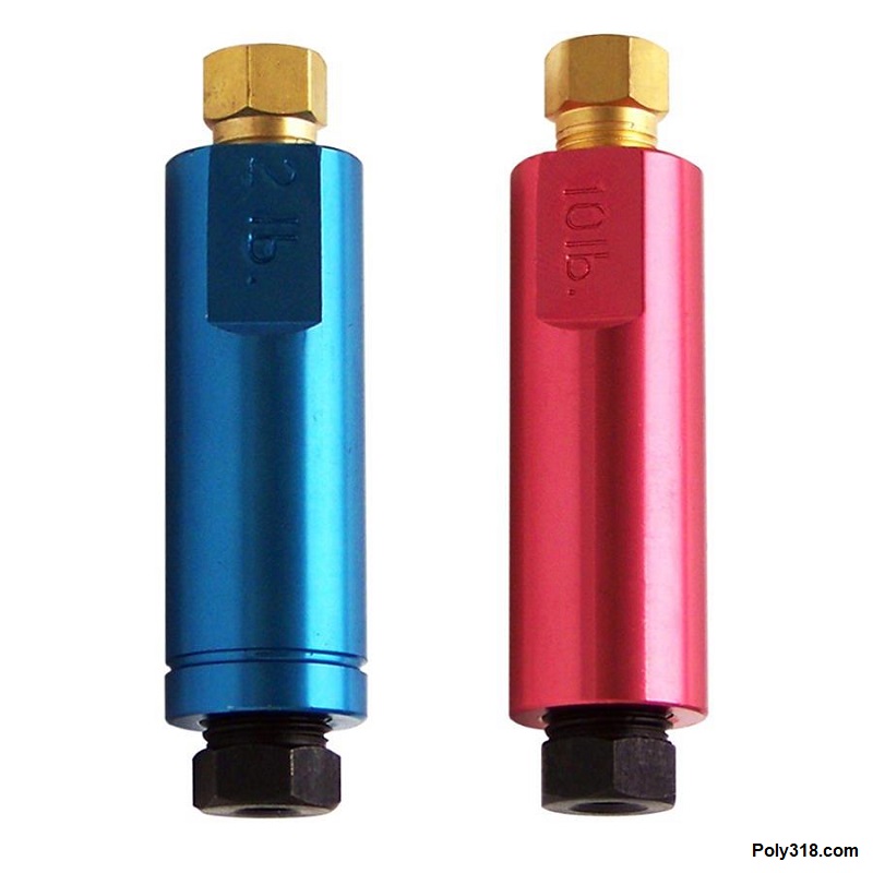
(common 2 psi and 10 psi shown)
Metering Valve: A metering valve is used only in front disc/rear drum systems to regulate line pressure at the start of braking and is most often incorporated into the combination valve, although stand-alone in-line units are available. As the master-cylinder piston is compressed by the pedal pushrod, the metering valve delays pressure to the front disc brakes up to a preset psi to allow full rear drum line pressure to apply the rear brakes that take a longer amount of time than the front disc brake calipers and pads. Once the rear shoes begin applying pressure to the drums and the line pressure increases to a preset psi, the metering valve moves to allow pressure to flow to the front disc circuit. Without a metering valve in a front disc/rear drum system, the braking from front to rear will be unbalanced causing harsher body diving in the front during hard braking and more wear to the front pads and rotors over time since the rear brakes are not functioning as often as they should.
The other function of the metering valve is to lock out a circuit in the even of a leak.
Distribution Block: A distribution block is a chunk of metal (usually brass or aluminum) that takes the single front and single rear feeder lines coming from the master cylinder and splits them into different configurations; the block can include a port for the brake light switch. For classic cars, the most common configuration is to take the single rear feeder line from the master to a single rear feeder line out to the rear brakes and to take a single front feeder from the master and come out of the block with two separate branch lines for the left front and right front brakes. Some modern vehicles use single-in/dual-out for both the front and rear circuits or have even more ports to run to specialized components and sensors.
Brake Pressure Differential Valve and Switch: This valve serves two purposes. The primary purpose that can benefit classic cars is once one circuit (front or rear) losses pressure, the valve trips, locks out the leaking circuit, and diverts the fluid from the both master cylinder reservoirs to the healthy circuit. Without the valve locking out the leaking circuit, that circuit’s reservoir would drain. If one wants this safety feature, the pressure differential switch must be left but does not need to be wired.
While not applicable to classic cars unless the owner wants to add an indicator light, the secondary purpose of the brake pressure differential valve is to trip a plunger switch that illuminates a dash light and throws an ECM code if either the front or rear circuit losses pressure. This is not a brake light switch that closes when pressure is applied but a switch that closes when the valve trips to one side and engages the switch’s plunger.
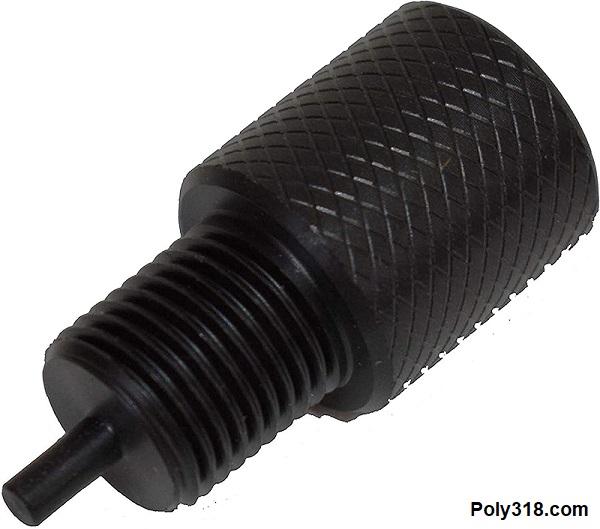
Extremely important for bleeding systems with a pressure differential valve, the switch must be temporarily replaced with the bleeding tool (Figure 2c) that locks the differential valve in neutral (untripped) position for the fluid to properly flow during bleeding. If the tool is not used, the valve will see no signal from a dry circuit and can easily trip and lock out that circuit thinking there is a leak. The unit must be dismantled to reset the valve, which adds a lot of time to bleeding the system. Once bleeding is completed, the metal tool can either be left in to delete the pressure differential function by locking the valve in neutral, or it can be replaced with the switch to keep the safety function.
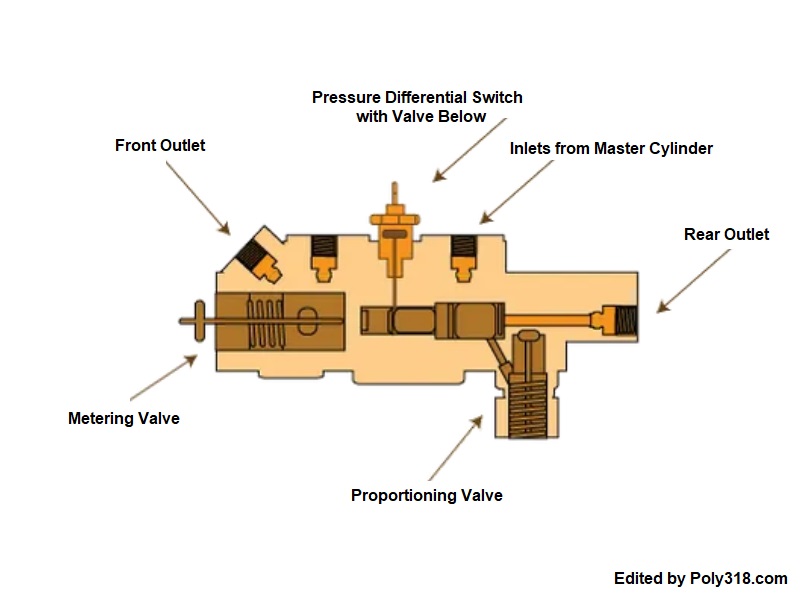
Combination “Combo” Valves: We now come to the almighty combination valve, which can mystify people–but keep in mind that not all combo valves are created equal, and there are different styles. The combo valve combines multiple valves and functions as a distribution block to simply the system (Figure 2d). It’s also an aesthetically appealing and cheaper alternative to having multiple aftermarket in-line valves and tee fittings. When selecting a combo valve, all the following elements of the master cylinder and system requirements must be taken into account:
Four Wheel Drum Combo Valve
- Include residual valves if not in the master, proportioning valve, and optional brake pressure differential valve and switch.
- Should not include a metering valve.
Front Disc/Rear Drum Combo Valve
- Include a rear 10 psi residual valve if not in the master, proportioning valve, metering valve, and optional brake pressure differential valve and switch.
- Should include 2 psi residual valve for front discs if master is mounted below the caliper elevation and does not include a residual valve. Otherwise, no 2 psi residual necessary for the disc circuit.
Four Wheel Disc Combo Valve
- Include proportioning valve and optional brake pressure differential valve and switch.
- Should not include the metering valve.
- Should include 2 psi residual valves if master is mounted below the caliper elevation and does not include residual valves. Otherwise, no 2 psi residual necessary.
Brake System Plumbing
Terminology: To clarify the terminology I use in this article since terms are often incorrectly thrown around, the hard metal that carries the pressurized brake fluid is called “line.” The flexible reinforced rubber that carries pressurized brake fluid is called “hose.” While people use the term “tubing” thinking it is interchangeable with the hard line, there is no “tubing” in an automotive brake system since tubing that carries fluid is flexible and un-reinforced for low-pressure purposes like vinyl tubing; metal “tubing” is used for structural purposes like a chassis or roll cage and does not carry fluids.
Routing: The most common brake line routing for our classic cars is a single feeder line coming out of the master cylinder that tees into two separate branch lines running to the left and right front wheel brake hoses and a single feeder line coming out of the master cylinder that runs to the rear end brake hose and then tees off to branches for each wheel cylinder or caliper brake hose. Somewhere in this system–whether in the master cylinder like many factory single-reservoir master cylinders, a combination valve, a distribution block, or in the front or rear circuit–lies the brake light switch. Lines should be routed for the most practical protection from moving/shifting parts, rub points, road debris, exhaust heat, and to limit flexing. For example, it’s unwise to run brake lines on the bottom of the frame rail/crossmembers, across parts that move such as the body, or too close to headers/exhaust manifolds unless they have adequate inner and outer ceramic coating to greatly reduce the heat.
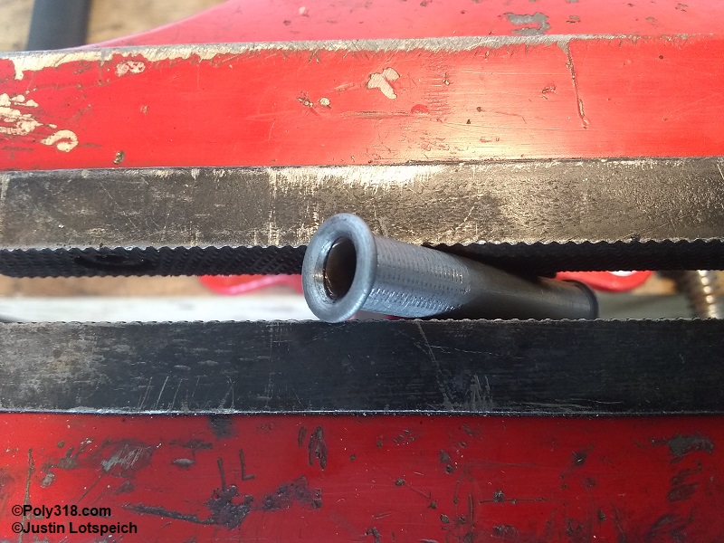
Line Protection and Fastening: Brake lines–aside from those designed to provided some flexibility like those between the master cylinder and chassis–should be well supported using strong clamps. I prefer using Adel clamps since they provide strong support, protect the line in a rubber sleeve, and are aesthetically appealing, but there are different steel clamps available including the factory type that snap into holes in the chassis. Sections of line that move around sensitive components like the engine and suspension should be supported more often than sections more secure and less likely to flex such as those running along the frame rail from the front to rear of the vehicle. To assist with protection around likely rub points or areas that may be damaged from tools or moving parts, coiled line protector often called gravel guard that slides over the line before finishing the flares is a wise addition. Gravel guard is available for the most popular line sizes including 3/16″ – 3/8″.
Line Material: Brake line comes in multiple materials including zinc-plated mild steel, stainless steel, poly-vinyl fluorine (PVF) coated mild steel, and copper-nickel plated mild steel. Pure soft copper line like that used for oil pressure gauges or refrigerator water dispensers should never be used for automotive brakes since it cracks easily with work hardening from vibrations and flexing and is extremely easy to damaged. Mopar, as with the vast majority of automotive manufacturers to this day, used mild steel zinc plated tubing, which is also the most common type restorers and builder use and what I prefer since it is strong, produces clean bends and flares without the need for expensive equipment, holds up well to the elements, and looks “normal” and period-correct. When it comes to brake line material, I think the adage of why reinvent the wheel applies.
Stainless steel line may seem appealing since it is the best option at resisting damage and corrosion, but beware of the pitfalls. Stainless lines require expensive specialized equipment to properly create double-inverted-flares due to the alloy’s hardness. I once experimented with 3/16″ stainless line that I got for a song at a swap meet, and I’ll never use it again. Bending the 3/16″ line wasn’t an issue with the type of hand bender I use, but flaring the line shattered my quality KD flaring die and destroyed the flaring tool tip when it cut in a deep groove when I made the inverted flare. That stainless line experiment ended up costing me a new KD flaring die and flaring tip. Even with the necessary tooling to flare stainless line, the connection between the master cylinder and the chassis can be problematic since the stainless alloy is much harder and therefore more rigid than mild steel, so it’s more prone to cracks from work hardening as the master cylinder and chassis move somewhat independently. For a visual, if you take a straight length of 3/16″ mild-steel line and 3/16″ stainless line and bend them back and forth repeatedly the same degree, the stainless line will crack before the mild steel. Work hardening applies to automotive brakes because each time the brake pedal is pressed, especially on manual systems without a power booster that require more pedal pressure, the master cylinder flexes at the firewall and pulls/pushes the brake lines up and down that are attached to the master and again down at the chassis. Normal vibration and bumps on the road also shake/sway the body at a different rate than the chassis due to the rubber body mounts, and this movement also flexes the lines attached to the master cylinder and chassis. Mild steel tubing, especially when using a loop in the line from the master cylinder to the chassis, handles these flexing dynamics better than stainless steel that will work harden quicker. Many systems that use stainless lines deal with this work-hardening issue by using reinforced hydraulic hose (e.g. braided stainless or high-pressure AN hose) to run from the master cylinder to the chassis, but these hoses definitely don’t look period-correct for classic builds.
In recent years, PVF-coated and copper-nickel plated line has been pushed by large automotive supply store chains as “the leading DIY alternative to zinc-plated,” but there’s a lot of hype with little benefit compared to the downsides. PVF-coated line sounds like a great idea and might one day develop into a superior line, but as of now I wouldn’t use it. I’ve run across PVF-coated brake lines at the salvage yard with troubling deep corrosion (not just surface rust) between the PVF and steel where water got in at the flares or nicks in the coating. Copper-nickel plated lines are made from a softer steel allow and are easier to damage during installation and from road debris than zinc-plated. While only my aesthetic opinion, I think copper-nickel plated line looks awkward on automobiles made after about 1925 since there is very little visible and unpainted copper or brass used, especially on 1950’s – 1960’s Mopars, aside from water and oil fittings and the oil pressure gauge copper line. Seeing a bunch of copper lines running in the engine compartment and underneath the vehicle looks out of place to me, but the main reason I wouldn’t use the copper-nickel plated line is the danger of picking up a tear from a rock or other road debris where zinc-plated line wouldn’t suffer damage.
Line Diameter: The most common line size for automotive brakes is 3/16″, which can be used throughout the entire system. Some systems with rear drum brakes use a 1/4″ feeder line to run from the master cylinder back to the rear end brake hose and then tee into 3/16″ branch lines on the housing for each wheel cylinder. There’s nothing incorrect with using a 1/4″ line in this way, but a 3/16″ line is perfectly suitable and was often used by the factory.
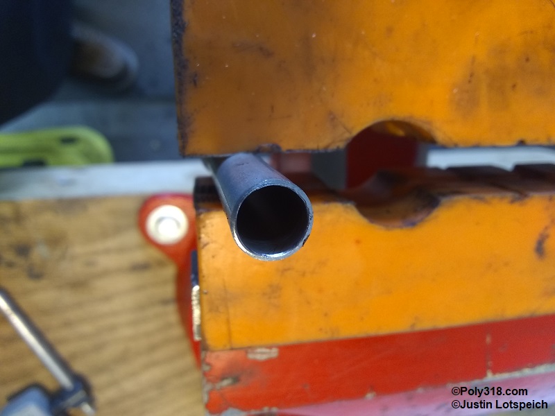
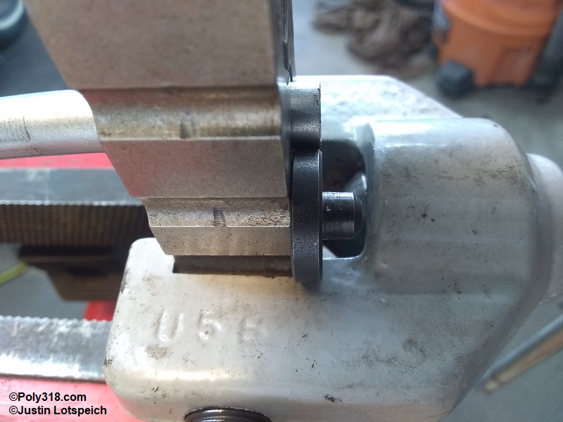
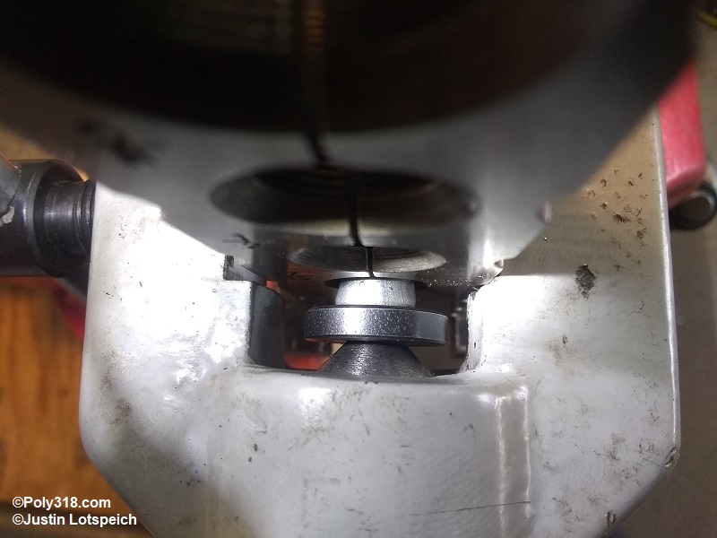
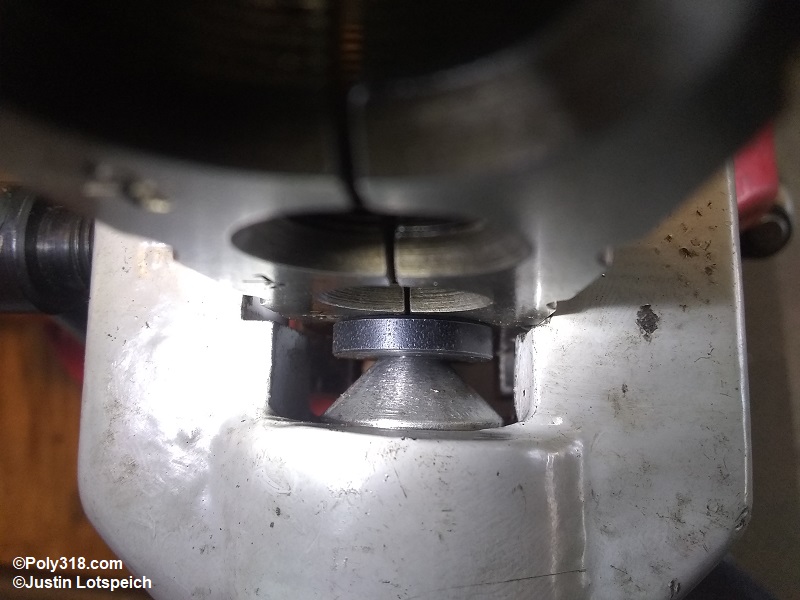
Creating 45 Degree Double Inverted Flares
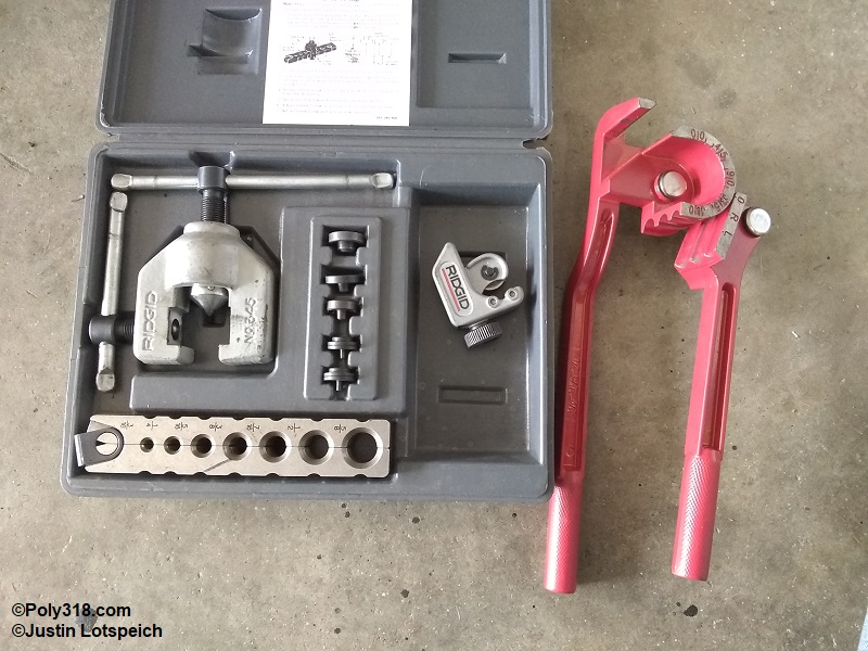
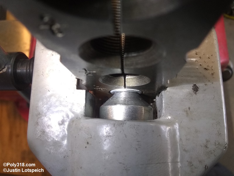
Before getting into fabricating the system and lines, I want to explain how I create double inverted flares. The tool I use is a Rigid model 345, which does a great job clamping the line without decreasing its diameter and producing flares (Figure 3a). To create a double-inverted flare, I first ream the inside of the line to remove the lip from the cutting wheel (Figure 3b). I slide the line through the clamping tool allowing the line to stick out of the beveled side of the tool about 1/4″ and slide the flaring tool over the clamp from the hinged side. I then secure the clamping tool in a bench vice down at the hinged side. Holding the die backwards up against the clamp, twist/slide the line in or out until it is flush with the die (Figure 3c). Insert the die into the line, bring the flaring tool up to the die, and turn the tool until the flaring cone just touches the die without pushing the line in to center the tool. Tighten the side screw of the tool very tight against the clamp to compress the line. I place a drop of oil onto the tip of the flaring cone and die, which helps keep the cone from galling. Tighten the cone to fold the line until the die seats firmly against the clamp (Figures 3d – 3e). Back off the cone enough to remove the die, and run the cone in tight against the line to produce the inverted flare (Figure 3f). After removing the flaring tool and line from the clamp, I use a wire brush to clean off the flare and line where it rode in the clamp and inspect the flare for proper form (Figure 3g). After both ends are flared and brushed off, I blow compressed air through the line to clean out any debris.
Fabricating the Master Cylinder, Combo Valve, and Feeder Line System
I’ve spent a lot of time going over all the different elements of the brake system in preparation for describing how I went about designing and building an updated system for my 1956 Dodge coupe. Note that I don’t discuss power brake boosters because I am not using one on this build. I prefer a harder pedal feel in classic cars since it helps with delicate situations on curvy roads or road course tracks, and it makes for a cleaner engine compartment. The 1″ bore master cylinder I’m using coupled with the 1956 Dodge pedal ratio is also plenty manageable without a power booster.
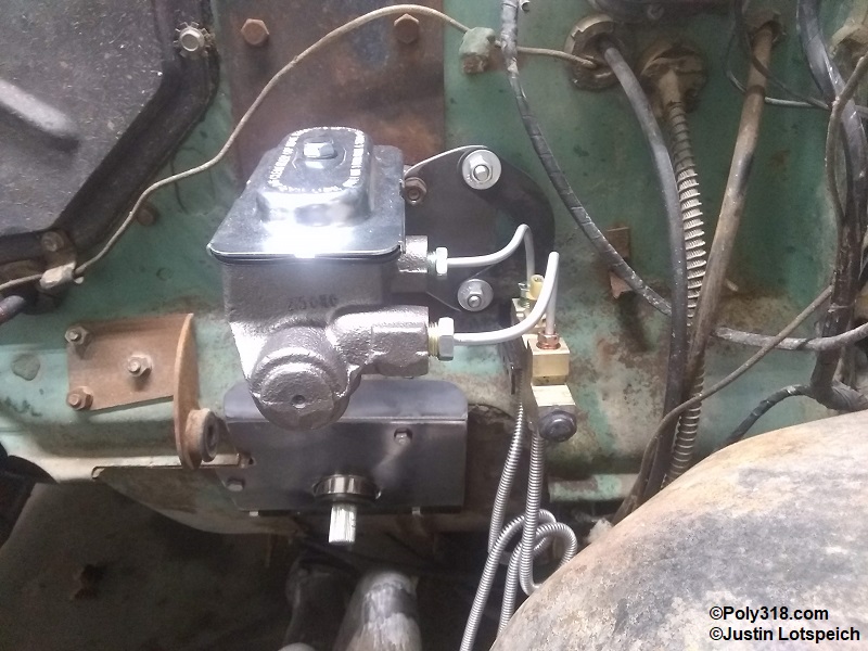
Master Cylinder: With the four wheel disc brakes and wanting a 1960’s look under the hood, I went with the even reservoir master cylinder MC36221. To address the 10 psi residual valves incorporated into the master cylinder, I gently screwed a #8 wood screw into each of the exit ports which eventually bottom out and push the inner copper cone out of the port (I neglected to photograph this step). I removed and discarded the rubber residual valve behind the cone and push the cone back into the port. Now the master has no residual valves. After removing the 1956 factory master, I bolted up the new master (I will bench bleed it at a later point after fabricating the system). Note that the metal tab on the mounting flange is used only for packaging to keep the piston from popping out and should be removed and discarded for the final installation.
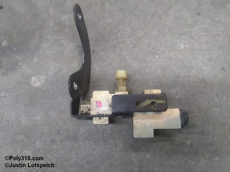
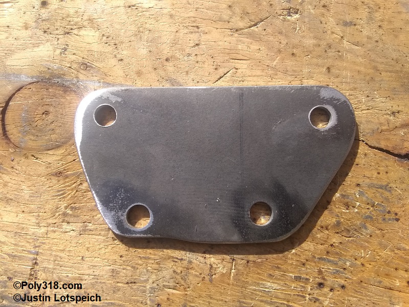
Combination Valve: After much research using parts catalogs for vehicles from the 1970s onward and inspecting vehicles at my local salvage yards, I settled on the combination valve used on 1997 Jeep Grand Cherokees with front disc and rear drum (Figure 4a). The combo valve includes the distribution block with a configuration of one inlet in and two out for the front and one inlet in and one out for the rear. The ports use 3/8″-24 and 1/2″-20 double inverted flare fittings. The combo valve has a preset proportioning valve. The combo valve does not include residual valves or a metering valve, which I don’t need or want for four wheel disc brakes with the master cylinder mounted to the firewall. The combo valve includes a brake pressure differential valve that I locked out with a metal bleeder tool I describe in the “pressure differential valve” section above. This unit can be purchased new, but they are $80; I pulled the photographed one at the salvage yard for $8. The combo valve also includes a mounting bracket that originally attached to the Jeep’s brake booster, so to attach it to the 1956 Dodge I build a bracket out of 1/8″ steel plate that attaches to the mater cylinder mounting studs (Figure 4b).
Feeder Lines from Master Cylinder to Combo Valve: I bent up short feeder lines from the master to the combo valve using the tubing bender (Figures 4c). The rear circuit, which is the front port on the master and combo valve, takes a 9/16″-20 male inverted flare nut at the master and a 3/8″-24 male inverted flare nut at the combo valve. The front circuit, which is the rear port on the master and combo valve, takes a 1/2″-20 male inverted flare nut at the master and a 1/2″-20 male inverted flare nut at the combo valve.
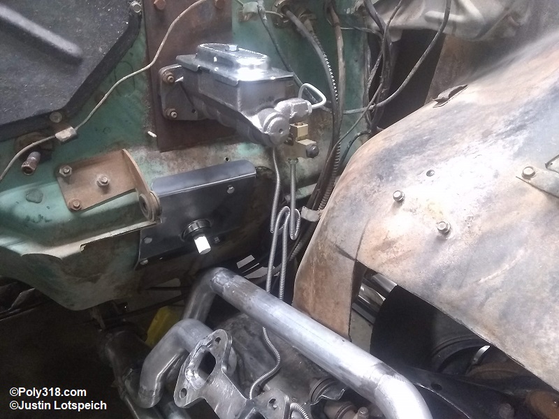
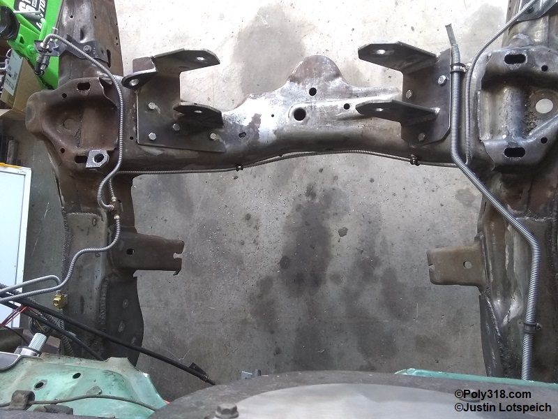
Feeder Lines from Combo Valve to the Chassis: These feeder lines take special consideration since they are attached to the body and chassis and receive the most amount of flexing in the system. The optimal configuration uses a loop in the lines that provides additional length of line allowing flexibility without straining and work-hardening the lines and connections. Quality 3/16″ line is easy to bend in these loops without kinking, and I placed a piece of 1-1/2″ metal exhaust tubing (pvc would work too) in a vice as a form and wrapped the lines around it. I paid attention to the direction of the loops in order to give each line clearance from each other, the firewall, and the inner fender (Figure 4d). I routed the front circuit feeder down to the frame rail and over to a 3-way 3/8″-24 double inverted flare tee fitting with an integrated bracket for mounting to the chassis (Figure 4e). I routed the rear circuit from the combo valve down to a 2-way 3/8″-24 double inverted flare and single 1/8″ NPT tee fitting with an integrated bracket for mounting to the chassis (Figure 4f). When I was happy with the routing, I installed the appropriate nuts for the combo valve ends and flared the lines. The front circuit combo valve outlet port (the rear port) takes a 1/2″-20 male flare nut, and the rear circuit outlet port (the front port) takes a 3/8″-24 male flare nut. With one end of each line flared, I slid on stainless steel gravel guard, installed the 3/8″-24 nuts for the chassis tees, and flared the ends. The final step for the feeder lines was to mark the chassis at the tee brackets and drill and tap the holes for 1/4″ bolts to hold the brackets.

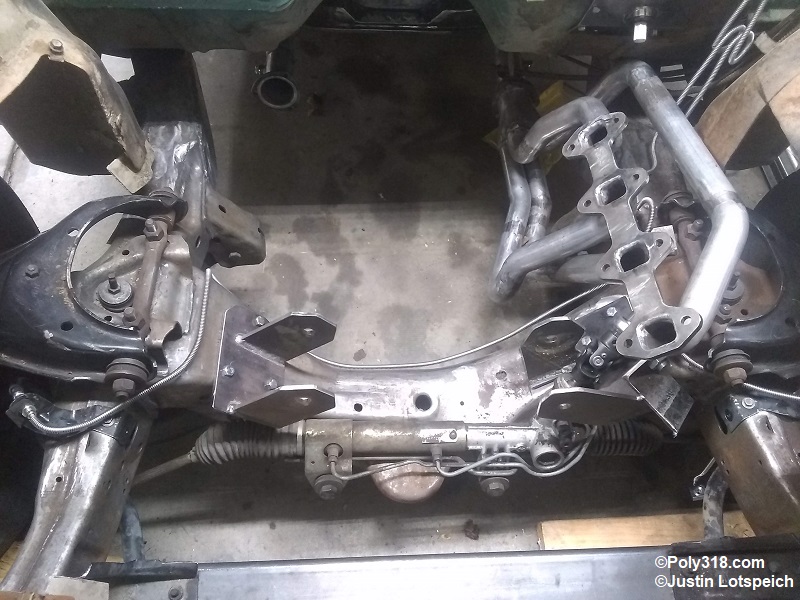
Front Branch Lines: From the chassis tee where the feeder connects, I ran a branch line to the left front caliper brake hose and another to the right front caliper brake hose taking the right branch behind the front engine crossmember and up over it at the right frame rail (Figure 4g). This routing best protects the lines versus running them on the front of or underneath the crossmember. I utilized the Dakota caliper hose brackets and routed the branch lines to them. Once I was happy with the routing, I installed a 3/8″-24 nut onto and flared each end, slid on gravel guard, installed 3/8″-24 nuts, and flared the ends. I installed the lines, placed enough Adel clamps to secure the lines, and drilled and tapped the chassis for 1/4″ bolts to hold the clamps (Figures 4h).
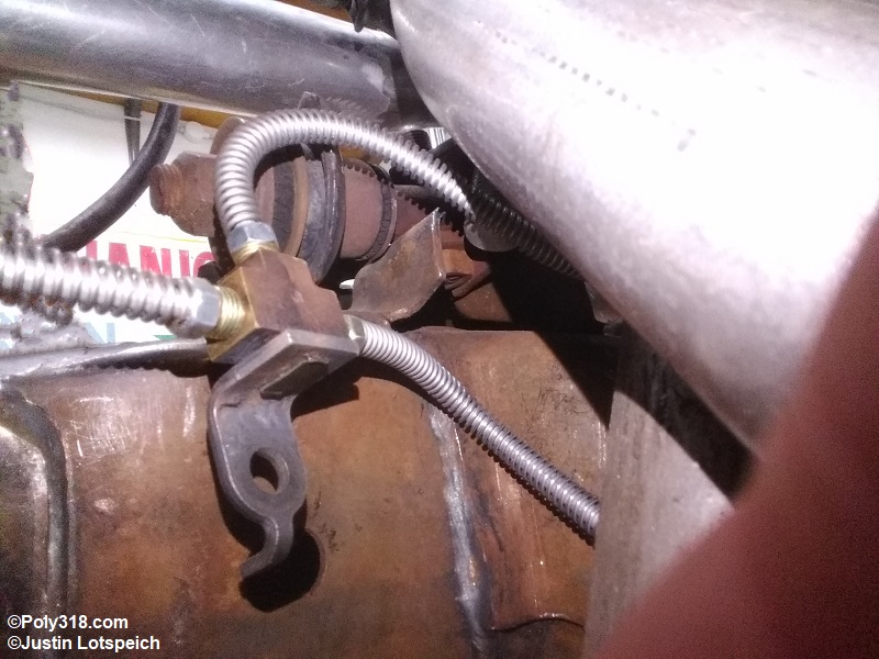
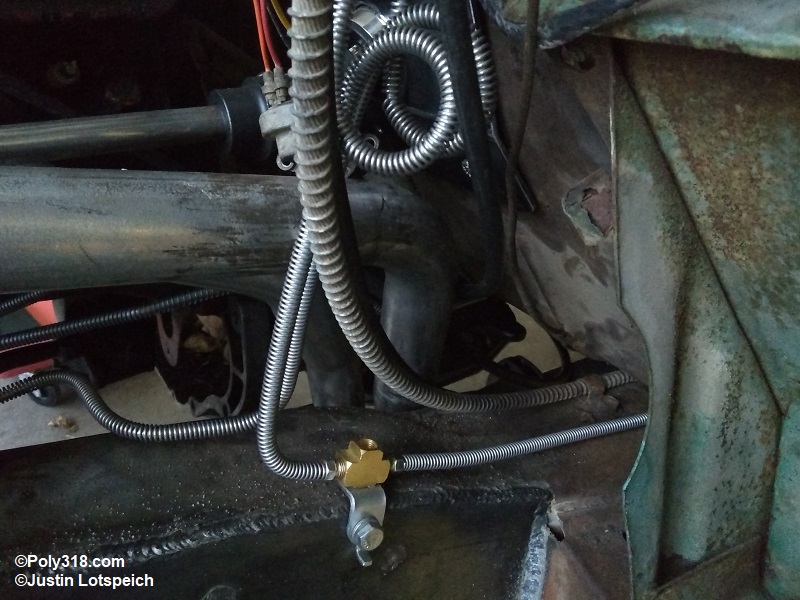
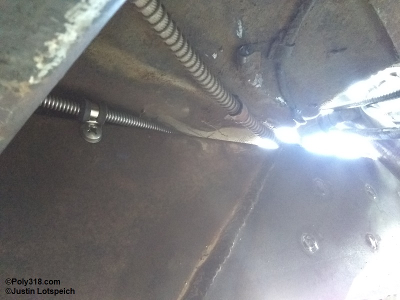
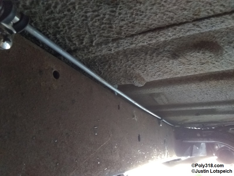
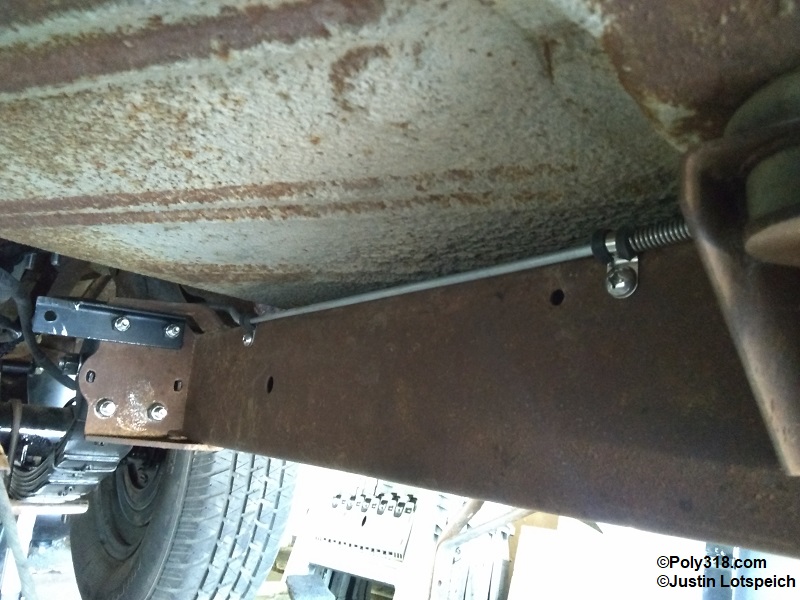
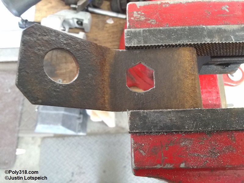
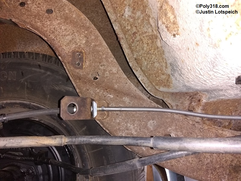
Rear Branch Line: The chassis tee for the rear branch has three functions: One port connects the feeder line from the combo valve, another the rear feeder line, and the 1/8″ NPT port connects the brake light switch (Figure 4i). I took the rear feeder line back on top of the frame rail and jogged it over to the inside top of the frame rail just behind the transmission crossmember (Figure 4j). I ran the line through the middle body mount back to the front leaf-spring perch (Figure 4k). Before the leaf-spring perch, I jogged the line toward the outside of the frame rail and then straight back (Figure 4l). With the Ford 8.8″ brake hose installed, I played around with the best routing of the hose. I removed the 1956 Dodge brake-hose bracket, drilled a new hole, and shaped the hole using hand files to match the Ford 8.8″ hose end to keep the hose locked and from spinning in the bracket (Figure 4m). I installed the bracket onto the brake hose, scribed the mounting holes onto the frame rail, and drilled and tapped the frame rail for 5/16″ bolts. After fastening the bracket, I ran the rear brake branch line to the hose and cut the line to length (Figure 4n). The rear branch line has three spots that require protecting from rubbing at the front, the middle body mount, and the rear. I placed Adel clamps to secure the line and to hold the gravel guard in place and scribed the Adel clamp holes onto the frame rail. After removing the branch line, I installed a 3/8″-24 nut and flared one end of the line. I cut three lengths of gravel guard and slid them onto the line in the appropriate order, installed the 3/8″-24 nut, and flared the end. I drilled and tapped the frame rail for 1/4″ bolts, installed the branch line, and secured it with the Adel clamps.
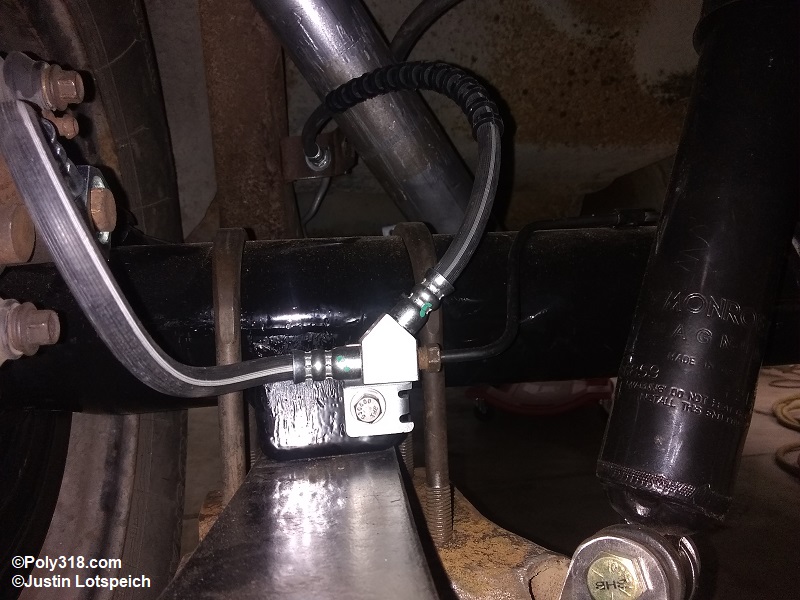
Rear End Branch Lines: The Ford 8.8″ uses a three-way brake hose that connects to the rear feeder line and runs to the axle housing where both the right wheel branch line and the left wheel caliper hose attaches (Figure 4o). The right wheel branch line was in perfect condition, so I cleaned it and reused it. For those using vintage rear ends with drum brakes, the brake hose typically attaches to the rear feeder line and has a tee fitting with two 3/8″-24 double inverted flare ports. From that tee, a length of 3/16″ line runs to the left wheel and another length to the right wheel. For damaged lines or lines with damaged nuts, I bend up new branch lines that follow the factory route to use the factory mounting tabs usually welded to the axle housing. Using gravel guard for about 6″ at the wheel cylinder connections is a good practice to protect the lines from damage since wrenches and sockets are used in this area for the wheel cylinder and backing plate fasteners.
Conclusion
After I fabricated the entire system and ensured all the lines were blown out with compressed air, I removed the master cylinder and bench bled it. After installing the master cylinder and connecting and adjusting the brake pedal pushrod, I bled entire system using a vacuum bleeder and finishing with traditional pedal bleeding. A vacuum bleeder isn’t necessary, but the $30 for a vacuum bleeder is well worth the saved time and ability for one person to bleed the system up to the final step of requiring an assistant to pedal bleed. Remember that if using a combination valve with a pressure differential switch, a metal or plastic bleeder tool should be installed in place of the pressure differential switch to stop the valve from tripping necessitating taking apart the valve to reset it. I hope that this article provides some ideas and information for others interested in upgrading or refurbishing their brake systems. I also wrote an article on upgrading the fuel system that includes fuel line routing and fabrication for those interested.