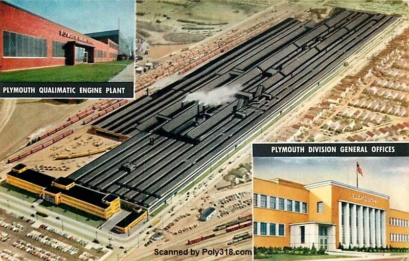
A-block Qualimatic Engine Plant:
Dawn of a New V8
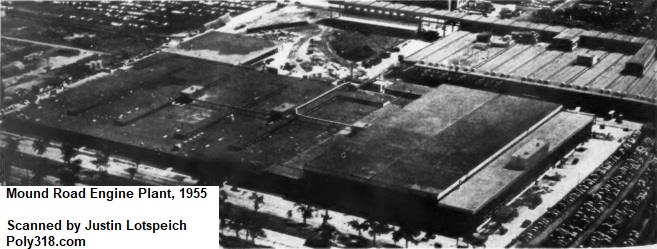
Mound Road Engine Plant, Detroit, Michigan
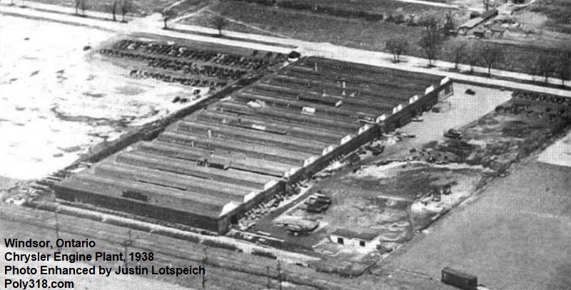
Windsor Engine Plant, Ontario, Canada

Introduction
Let us go then, you and I, for a tour of the Plymouth A-block design team’s drafting tables and engine manufacturing plant. “Who were the men and women who designed and built the poly A-block engine and plant,” I wondered. Not a single internet source provided credible information, but most provided what I would find is inaccurate information and assumptions. The search for answers led me into a huge historical research project that took me to obscure publications, factory documentation, designer notes, period manufacturing magazines, period equipment advertisements, and the Stellantis (formerly Chrysler) historical archives. Much of the content surprised me, particularly with how revolutionary the A-block and its engine plant designs were in the automotive manufacturing industry.
A misconception that is perpetuated online without evidence is that Plymouth designed the A-block engine as a cheap alternative to the Chrysler, DeSoto, and Dodge Hemis, but this myth is not supported by historical documentation written by Plymouth executives and the very people who designed the A-block, engine plant, and manufacturing equipment. The myth in fact confuses the A-block with the polyspherical heads Chrysler and Dodge designed to fit on their Hemi shortblocks (DeSoto never used a poly head). These Chrysler and Dodge poly heads were indeed designed as a cheaper production and servicing alternative to the Hemi heads while being able to use the Hemi shortblocks already in production, but they have nothing to do with the Plymouth A-block aside from the general polyspherical combustion chamber shape. I discuss myth busting other misconceptions in the history and myth page.
In reality, rather than wanting a cheap engine, Plymouth spent the most money ever for the time on developing the A-block engine, production processes, and plant. Three major considerations according to the A-block design team led to the development of the A-block and its American and Canadian factories. First, Chrysler Corporation had enough experience with the Hemi to know its design, production, and consumer limitations and desired to develop an entirely new V8 engine using current technology and tooling practices; Plymouth by not having its own V8 was the natural division to lead the new V8 program. Second, Plymouth wanted to remove human error from critical processes, such as torquing of fasteners that prior to the A-block had been done by hand and had led to delay in production and warranty issues. Third, Plymouth wanted to improve plant safety and quality of the work environment by implementing new air-filtration technology; removing almost all lift trucks (as in fork lifts) from the floor; and automating the most strenuous assembly lines and processes, such as fastening components with impact wrenches for many hours and lifting heavy parts on the block, cylinder head, and crankshaft production lines. The design team soon realized it was a natural conclusion to automate almost the entire process. While Plymouth does not specifically call out the economic reasons, it isn’t hard to see that automating more parts of the system saves money through increased production speed and efficiency; eliminating production workers; decreasing waste from human error; and decreasing warranty issues from human error during production.
I spent many months researching for this article and many more writing it, and I used whatever literature I could locate. Unfortunately, many of the factory photographs come from aged publications badly discolored or microfiche with poor resolution and brightness. I worked with Photoshop to lighten and clarify the images as much as possible, but photo details are still often lacking, and I have been unable to locate other hard copies for scanning. Some photos were so badly darkened I couldn’t even use them. I will continue to search for cleaner hard copies of the documents I found, but I highly doubt I will ever find them since they are obscure documents published in small quantities for internal or industry consumption, and some of the documents have been lost by those publications still in business due to fires and server crashes in the 1980s and 1990s.
Beginning Development of the A-block Engine Program
The first thing I cannot emphasis enough is that there was very little linear planning to the A-block program. What I mean is that while I lay out sections in this article by category for ease of reading as if we could map them on a timeline independent of the other sections, in reality the A-block program was revolutionary in that the engine, production methods, plant facility, and equipment were designed simultaneously and influenced by feedback from everyone involved from Plymouth leadership to the foremen training on the new production equipment. Prior to the A-block, the conventional method designed the engine first, followed by the production methods, then the equipment, ending with the facility. For reasons I cover throughout this article, the A-block design team ditched this conventional way of building a new engine. In early January, 1954, Chrysler Corporation demanded that the new Plymouth V8 A-block would be in full production by fall 1955 ready for use in 1956 models, which was criticized by many outsiders and doubted by many in Plymouth as an impossible task. It was January 1, 1954, and not a single engine, plant, or equipment blueprint existed. The engine would have to be in full-capacity production by October 15, 1955 at a staggering 150 engines per hour, leaving the Plymouth design team, equipment manufacturers, construction workers, and the production worker training team a little over twenty months to design, produce, and build the engine and plant and train the supervisors, maintenance worker, and production workers in time to pilot the assembly line at 50 engines per hour by a deadline of August 15, 1955.
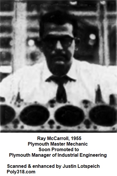
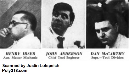
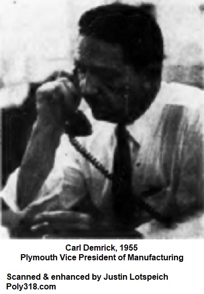
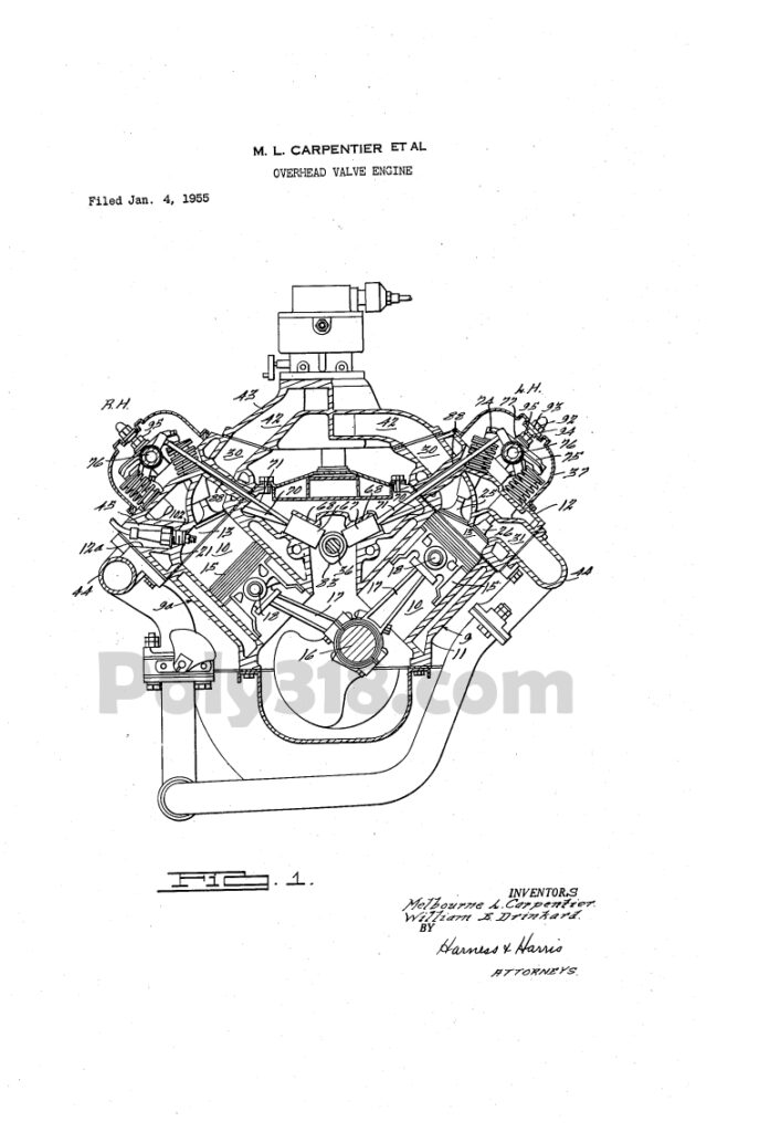
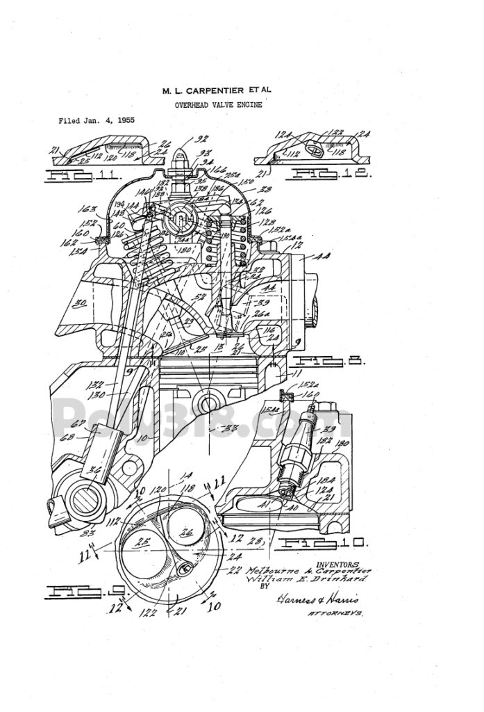
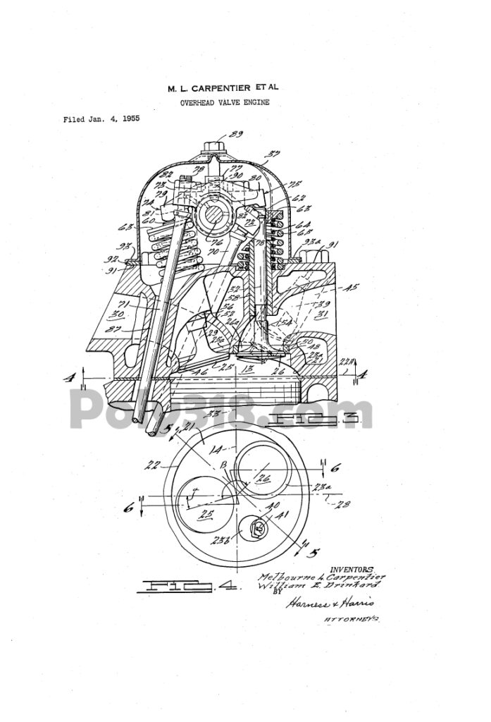
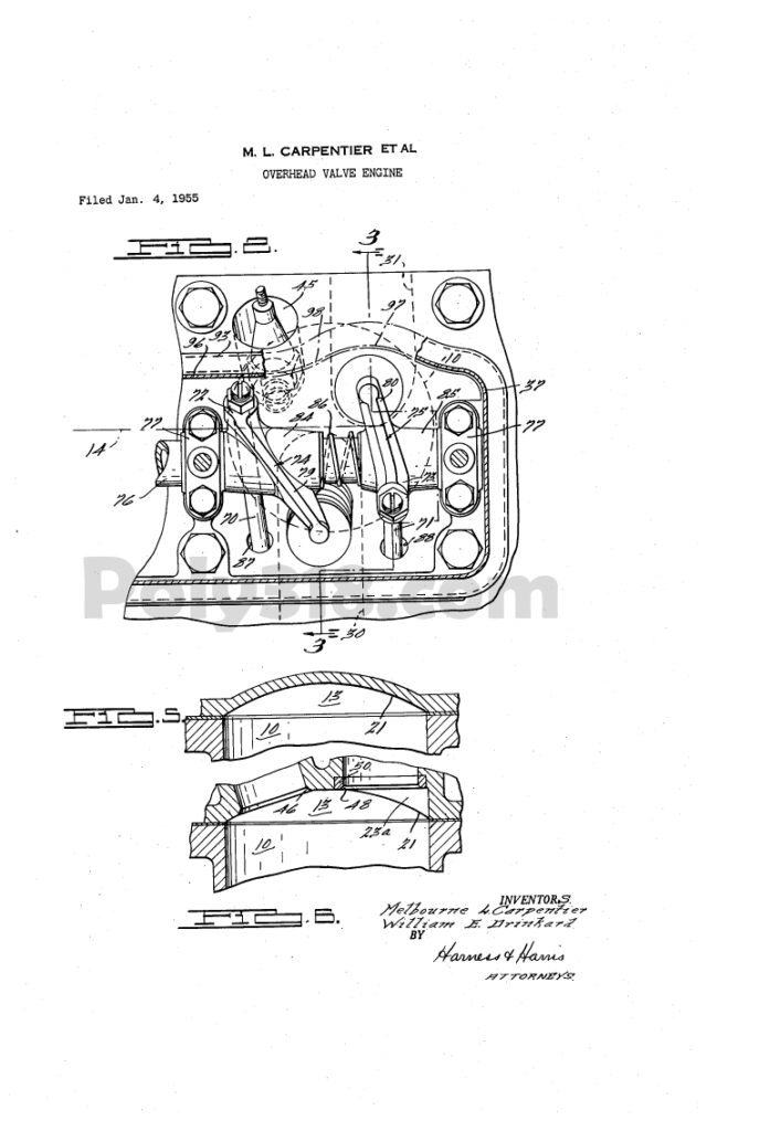
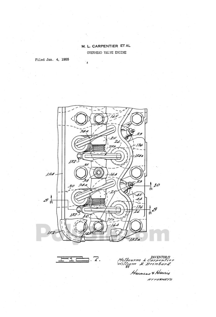
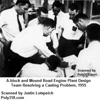
The design and production of the A-block factory and engine was overseen by Plymouth’s Chief Engineer Bob Anderson with a slew of other important figures (Figures 1a – 1d). The Engine Design team including Melbourne “Mel” Carpentier, William “Bill” Drinkard, and Bob Rarey was tasked with much of the A-block’s design but worked hand-in-hand with Plymouth’s Master Mechanic Ray McCarroll and his team who Plymouth’s VP of Manufacturing Carl Demrick in a 1955 article explains was a pivotal figure who had a hand in every decision made throughout the A-block V8 program. According to Demrick, McCarroll convinced upper management, the Engine Design team, Master Mechanic’s team, Plant Engineer team, and equipment suppliers that “processing of the engine would have to be done simultaneously with the actual designing of the engine. The ‘quality’ outcome of such a procedure rested entirely on the ability of Manufacturing to work together with Product Engineering.” Once the plan was set to design everything together, Chief Tool Engineer Johnny Anderson and Assistant Master Mechanic Henry Ibser set up their headquarters in the same office as the engine designers to help facilitate the simultaneous design and production of the A-block engine and factory, which was unheard of in the industry. For the purpose of this article, I refer to specific design teams when applicable and call the collection of teams the “design team” (Figure 1e).
Once the design team sketched out a rough design of the engine and plant blueprints (Figures 1f – 1j), focus on the equipment became paramount since many of the machines had to be invented or heavily modified from existing blueprints to meet the design team’s goals for the A-block and plant. According to Plymouth Purchasing Agent Wes Embury, discussion with equipment manufacturers for the plant (he calls them “suppliers”) started in July 1954. Of the 1,100 quotes received, Plymouth’s Manufacturing Committee and Master Mechanic’s staff chose 52 manufacturers to supply the plant. Rather than using the industry standard of putting equipment out for bid and using the lowest bidder, the Manufacturing Committee hand-picked top-tier suppliers with a proven track record working at Plymouth’s old plant considering the quality of their products and servicing contracts. Embury explains that from this list of suppliers, Plymouth chose those who had “the capacity to produce on time. [They] had to have complete engineering staffs including field engineers for ‘in-plant’ service. Primarily important, [they] had to have the quality of product that would conform to the standards and performance requirements of the Master Mechanic’s staff. . . . One company [Wesson] was responsible for all carbide cutting tools used through the plant. Another company [Sheffield] was charged with the responsibility of all air gaging equipment.” All major orders were placed by December 15, 1954. The entire machining and tooling procurement for the Plymouth A-block V8 program ended up costing a staggering $50 million, the equivalent of $544 million as of 2020—the most money ever spent on an automotive engine and plant at the time.
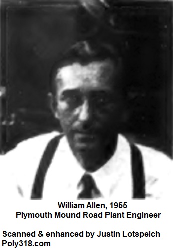
To facilitate the incorporation of multiple tooling manufacturers, those manufacturers were contracted to produce different entire sections of the assembly line. In many cases, this setup forced equipment manufacturers to collaborate and produce an entire section made up of multiple manufacturers’ equipment, some of which were competing machines. Shifting some of the coordination responsibility from the Plymouth design team to the equipment manufacturers expedited the design of the assembly line since multiple manufacturers and Plymouth’s design team worked on the project versus just Plymouth’s team. As the suppliers began fabricating the specially designed machines, Plymouth’s Master Mechanic’s staff sent members of its team to set up offices at the suppliers in order to facilitate necessary modifications in real time, yet another novel approach in the industry. The Mound Road Plant Engineer William Allen tasked plant electrical engineers with working directly with the equipment manufacturers since construction and equipment design would take place simultaneously so the plant architects could properly design the plant that was being built simultaneously.
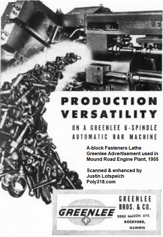
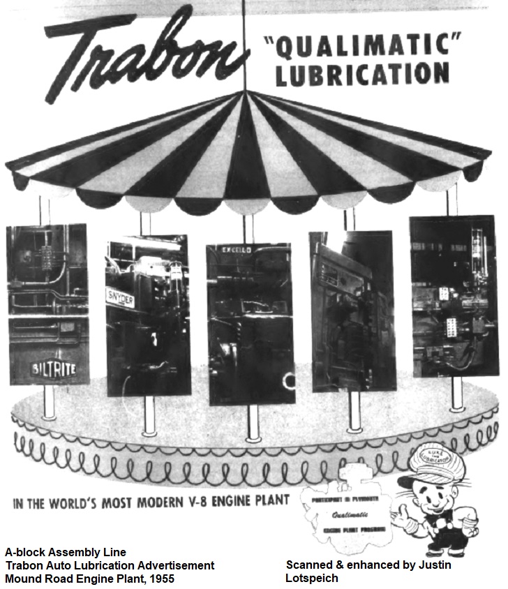
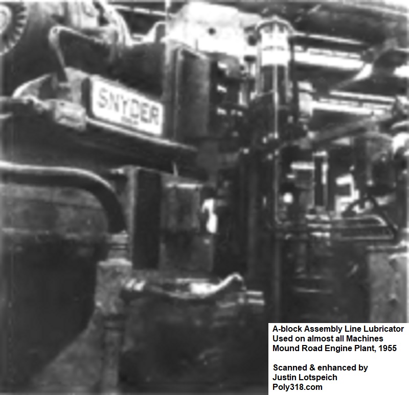
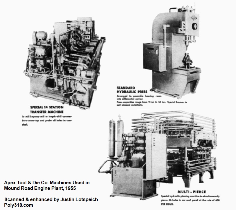
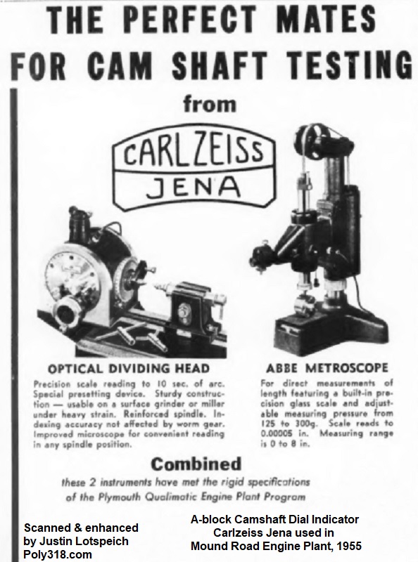
Powering the many different machines, a new 200,000-kilowatt electrical system was used. From the photos, descriptions, and equipment advertisements I have located, equipment manufacturers and machines ended up including Aerodyne dust collectors, filters, and air blowers; Airborne Instruments Laboratory camshaft and intermediate drive shaft gauging machines; Apex camshaft bearing installation machines; presses, and punches; Baird piston chucking machines; Barnesdril block boring machines; Beach oil pump air-leak testers; Bilt-Rite wire-brush machines; Blanchard connecting rod grinders; Buhr crankshaft and connecting rod dial-index machines, connecting rod machines, and drilling machines; Carl Zeiss Jena camshaft micrometers; Centri-Spray intake manifold washers; Cincinnati broaching machines and piston grinders; Colonial broaching machines; Crankshaft Machine Company crankshaft lathes; Cross transfer machines; Ex-Cell-O block and connecting rod boring machines; Fitchburg crankshaft mills; Frederic B. Stevens piston washers and driers; Gilman bearing installation machines; Greenlee fasteners lathe (Figure 1k); Heald “Bore-O-Matics” piston machines; IMF parts washers; Impco crankshaft straighteners, washers, polishers and demagnetizers; J.I.C. Electrical control panels; Krueger-Barnes camshaft machines; Landis crankshaft and camshaft grinding machines; Lapointe broaching machines; LeBlond crankshaft lathes; Lees-Bradner vertical camshaft gear cutter; Michigan Drill Head Company drilling machines; Micromatic “Turrent-Hones” connecting rod machine and bore gauges; Modern Industrial Engineering intake manifold mills; Motch & Merryweather connecting rod weight mill; Nankervis engine testing machines; Norton “Cam-O-Matics” camshaft grinders; Olsen crankshaft balancing machines; Rehnberg-Jacobson camshaft index trunnion machines and connecting rod presses; Schraner camshaft lapping machines; Seneca Falls “Lo-Swing” camshaft grinders; Morris “Exact Weight Scale” equipped with Shadograph piston and rod balancers; Schraner camshaft lapping machines; Sheffield automatic air-operated gauging machines; Snyder crankshaft drilling machines and rocker-shaft lathes; Sundstrand rigidmils; Syntron Vibratory conveyor hopper feeders; Thor torquing air motors; Trabon automatic lubricators (Figures 1l – 1m); Trio Tool Company connecting rod disassembly and stamping machines and piston-rod assembling machines. Toledo balance scales; Wesson carbide cutters and connecting rod Rigidcut mill; W.F. & John Barnes cylinder head drilling machines; WICKES crankshaft lathes; Wilson conveyors, loaders, and unloaders; and others including electrical systems, lubrication systems, cutting bits, etc.
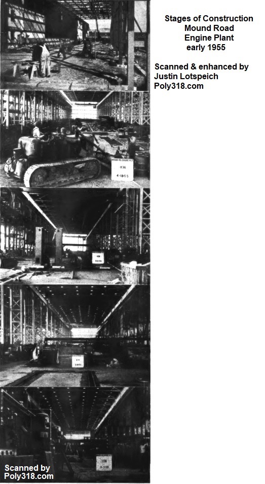
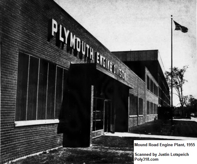
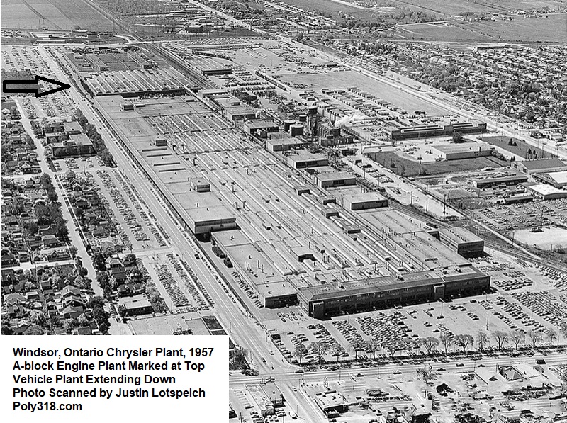
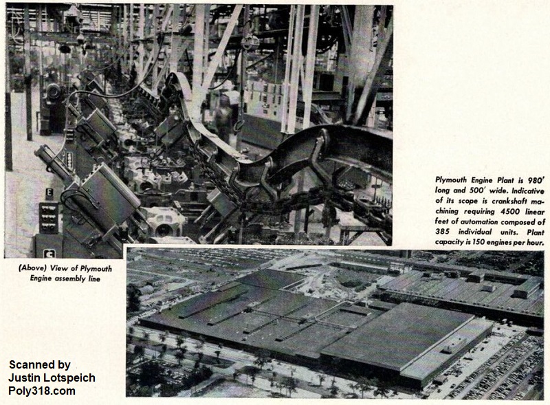
In January 1954, the Plymouth design team acquired an old Briggs Manufacturing Company factory on Mound Road, Detroit, Michigan that Chrysler Corporation had acquired in 1953 when it purchased the Briggs Manufacturing Company that specialized in automotive bodies after its owner Walter Briggs died. From 1953 – 1954, Chrysler Corporation had been using the building to produce aircraft parts but agreed to hand it over to Plymouth. To accommodate the design team’s intended block and cylinder head production lines, the Plant Engineer’s team expanded a high-crane area by 31,000 sq.ft. on the south end of the building, which took five months to complete (Figure 1n). The construction was so fast paced that they began installing manufacturing equipment before the renovation was even completed. They added an additional 40,000 sq.ft. to the northeast end of the building to house the Receiving Department and General Stores Department, which took four and a half months simultaneous with the other construction segments. The entire renovation added 71,000 sq.ft. to the plant and took 17,000 cubic yards of concrete. According to Plant Engineer William Allen, “In one two-month period, we ran a cement company right out of cement. Construction began January 24 [1954] and was completed July 19 [1954]. During the same period much of the production equipment was installed.” The plant was tasked with building the A-block engine assembly—originally in the 277 c.i.d. configuration but later the 301, 318, and 326. The design team agreed that the engine was to be produced in a “bobtail” assembly, meaning a complete engine from water pump through the bellhousing, intake manifold to oil pan but without the transmission, carburetor, generator, accessories brackets, starter, fuel pump, and distributor that were shipped directly to the vehicle assembly plants. These components were cheaper to ship directly to the vehicle plants due to weight, and processing, storing, and shipping them on the assembled engine was a damage risk that outweighed any benefit. The plant was 500’ wide x 980’ long with an “L” extension for 539,059 sq.ft. of floor area. The entire assembly process moved from the back of the building to the front. The plant was made up of almost 500 machines. The design team began calling the Plymouth A-block engine plant the “Qualimatic Mound Road Engine Plant” due to its location and revolutionary use of automation and superior machining and quality control practices. When it began pilot operations in late spring 1955, it housed the world’s longest assembly line and included a visitor’s area in the office that sold souvenirs (Figures 1o – 1r).
At the same time, Plymouth retrofitted an engine plant in Windsor, Ontario originally built in 1938 in order to produce the new 303 and eventually the 313 A-block for the export market (Figure 1s). They expanded the campus, adding a vehicle assembly plant for export vehicles (Figures 1t). Unfortunately, photos in Chrysler Corporation’s (Stellantis) archive have been lost to where I was able to find and only these photos.
Plant Innovation Discussed by the Master Mechanic
Master Mechanic Ray McCarroll said the Master Mechanic team’s primary focuses boiled down to quality production, low-cost production, and constant and dependable production. He compared the Qualimatic Mound Road Engine Plant to a vintage wine crop: “Such a facility comes along only once in a great while and is the result of a great many things that occur at exactly the right moment in exactly the right way.” McCarroll discusses in great detail the shift in doing business during the invention of the A-block and its plant. Prior to the A-block, engines were designed first, then the processing elements, and finally the facility. The issue with this approach by 1955 was that the three areas had become highly specialized to where an engine engineer tended to become tunnel-visioned on the engine without necessarily considering how a design element impacted production and how that production need impacted the facility construction. For the first time in mass-produced engine design and production, the A-block design team abandoned the old way of doing things and instead designed the engine, manufacturing process, and facility simultaneously with the three groups constantly working with each other with offices set up in the same buildings (Figure 2a).
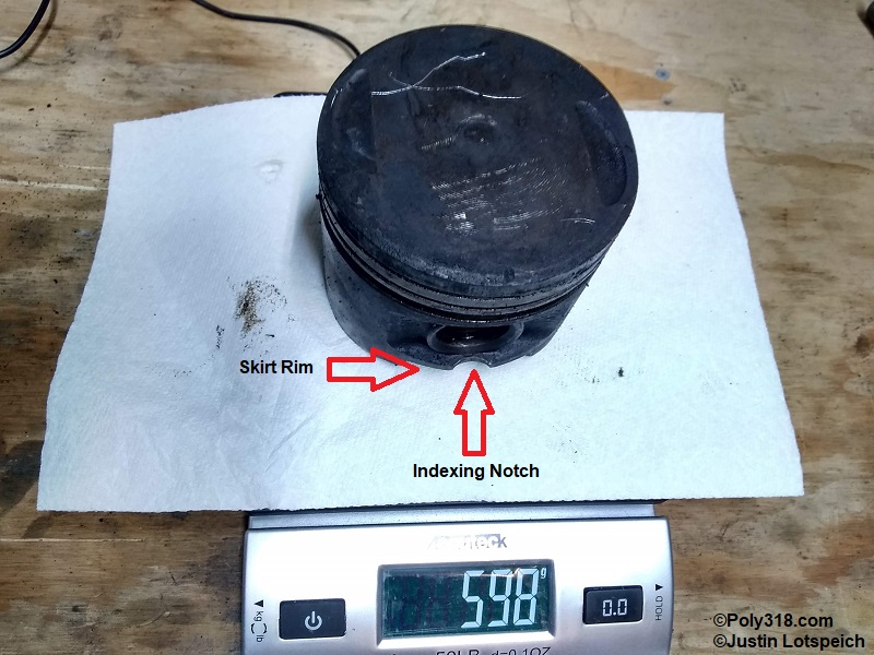
From this novel approach to engine design and manufacturing came major innovations. One example McCarroll gives is the piston assembly line, which answered a curiosity I always had about the A-block piston in that it uses a full skirt around the bottom versus casting the sides flat like other pistons of the era (e.g. a Chevrolety 265 piston). The Master Mechanic team in working out the design of the production approached the Engine Design team and asked them to place a rim around the bottom of the skirt allowing the pistons to roll on their side down the gravity shoots of the conveyor system, whereas a traditional flat-sided piston would not roll. The Master Mechanics also had the design team include a notch that the machines would use to both trigger limit switches and index the pistons radially. McCarroll explains, “By having pistons designed so as to roll, and with an indexing notch on the OD, a completely mechanized piston machining line was made possible.”
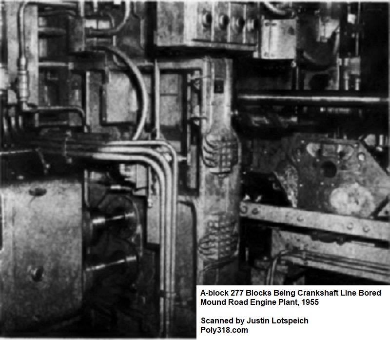
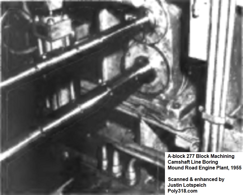
Some of the most significant innovations of the Qualimatic and A-block design according to McCarroll were combining complex machining operations into single multi-station machines in order to maintain uniform, strict tolerances (Figure 2b). With the machining I’ve done, I’ve found that the A-blocks are machined with extremely precise tolerances, such as the block decks, crankshaft and camshaft journals, etc. compared to both contemporary engines and even engines into the 1970s. According to McCarroll, prior to the A-block, engine manufacturers would clamp the block into one machine, perform one or a limited number of processes, unclamp it, move it to another machine, and repeat through multiple machines. For example, traditionally the block that was clamped in a crankshaft line-boring machine would be released, moved down the line, and then clamped in a camshaft line-boring machine. Inevitably, the two machines would have some difference in both clamping and tool alignment, introducing either inconsistencies or the possibility of inconsistencies that through the many different block machines would stack creating tolerances at the extremes and requiring regular machine calibration and downtime. To resolve this issue, the design team working with equipment manufacturers built entirely new machines that clamped the component on a moving conveyor and performed multiple operations passing through multiple machines that I go into further detail about in the different manufacturing sections below. This novel approach to machining would forever change engine plants moving forward.
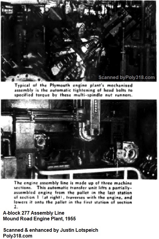
Another innovation with the A-block program was torquing fasteners. Traditionally, fasteners were torqued by hand via pneumatic impact wrenches, but the design team worked with equipment manufacturers to invent machines that automatically fed oiled fasteners through hoppers, gripped them, started them on the threads, and used compressed air to torque them to specification. These new types of multi-spindle way-type pneumatic heads performed the engine’s more than fifteen torquing operations (Figure 2c). The designers used three types of Thor air motors to power the heads that were specially adapted by the equipment manufacturer Cross to fit into the spindle head’s air manifold. Each motor was adjustable for the desired torque specification and included a thick insulator to decrease manufacturing decibels by half compared to traditional pneumatic impact torque wrenches, adding to plant safety and workplace quality. The innovative design allowed production workers to quickly swap out air motors for regular maintenance, repair, and calibration. After all the automation, only three threaded fasteners on the entire engine required manual torquing by a production worker due to inaccessibility. While no factory literature confirms these hand-torqued fasteners, if I had to guess I’d say some of the intake manifold bolts that are tight to the runners may very well be these fasteners since every other fastener on an A-block is easily accessible with a thick impact socket.
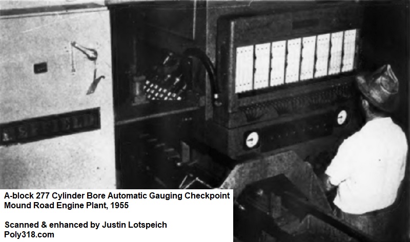
Another innovation in the Qualimatic plant was automated quality control. The plant used multiple Sheffield automatic air gauges throughout the different lines to check tolerances after most machining procedures (Figure 2d). Parts that fell within tolerance continued moving down the line, while parts that fell out of tolerance were automatically ejected from the assembly line for review by an operator or production worker to decide if the part could be run back through for correction or needed to be sent to the scrap rail car for recycling. Before the A-block, most of this quality control was done manually, which introduced human error and took more time.
Automated Conveyor System
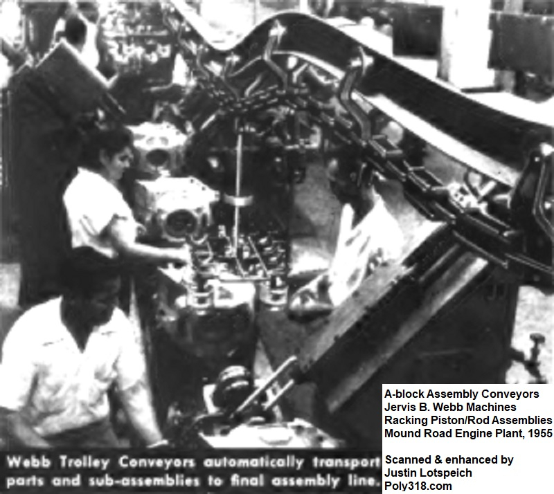
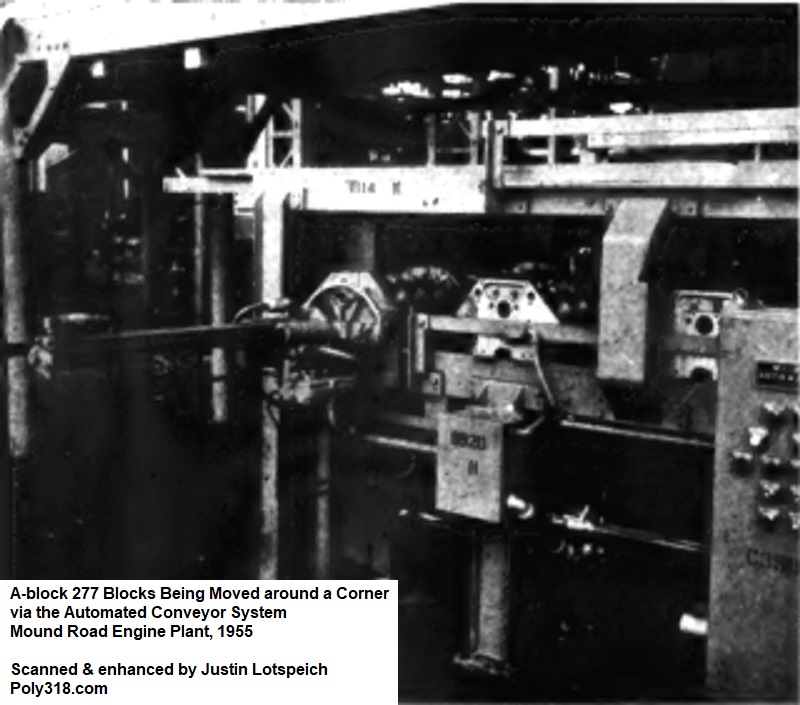
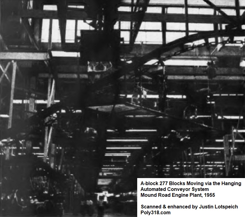
Throughout the entire plant, conveyor systems built by equipment manufacturers Jervis B. Webb, Wilson, and Cross automated the movement of components and assembled parts. There were five miles of overhead monorail conveyors to assist with transferring some components not handled by roller and belt conveyors (Figures 3a – 3d). The automated system of conveyors significantly decreased the need for jitney lift trucks (what we typically know now as forklifts) down to just nine for the entire plant and in limited areas, which in turn drastically increased plant safety and efficiency.
The conveyor system was not simply a single unit that ran at one rate of speed but was a complex system made up of different conveyors programmed for the speeds required by the machining processes. The speed would increase and decrease automatically, designed after testing how much time a certain machine required to perform its tasks and how much time operators and production workers needed to complete any manual tasks. The equipment operators had the ability to quickly override the conveyor speed to slow it in the event of an issue, such as a broken cutter or malfunctioning tool, that required more time for them to complete their task, at which point the conveyor would be placed back into its default speed.
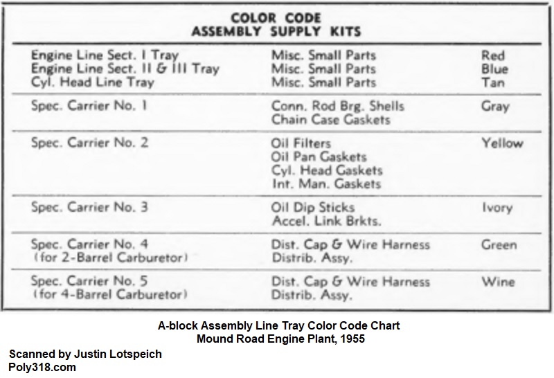
Small components were carried overhead in color-coded Royalite plastic trays via a Jervis B. Webb conveyor system designed by the Plant Engineer team’s Bob Patterson (Figure 3e). Small parts were delivered in sorted packages to specific stations on the line with the tray color identifying to which section of the assembly line the parts belonged. Using connecting-rod assemblies as an example, the different components after machining (pistons, pins, pin locks, connecting rods with matching caps, rod bolts, nuts, and bearings) were assembled by different stations and eventually were placed in weight-matched sets of eight on overhead conveyor racks. The design team explained how this system worked: “At the beginning of the line, the operator removes a tray designated for section 1 from the tray conveyor and places it between two cylinder blocks starting along the final assembly machine. At the completion of the assembly operation in section 1, the emptied tray is removed and placed in a ‘homeward bound’ hanger on the overhead conveyor. A special automatic unit lifts the engine from the end of section 1 and lowers it onto another pallet for its trip through section 2. The pistons to be installed are brought in matched sets by overhead conveyor, which descends and travels immediately over section 2 of the assembly machine. The overhead conveyor is synchronized with the assembly machine so that one set of pistons moves in unison with a particular engine on the line. This permits the pistons to be removed from the conveyor hanger one at a time and installed in matched sets without fail.”
For the first time in mass engine manufacturing, the entire assembly line was automated including transferring parts from one machine to another. Prior to this plant, other plants had been using individual automated machines that an operator would control via buttons/levers, but they lacked true automation. In contrast, the Qualimatic A-block plant continuously moved parts down automated conveyors and rotating and flipping machines to pass the parts into machines, index them, clamp them, machine them, pass them to the next machine, index them, clamp them, machine them, and so forth. Operators and production workers were still necessary to load and unload some machines, such as the connecting rods, to supervise equipment, and to troubleshoot and repair issues like worn and broken cutters/bits, but the role of the operators and production workers became more skilled in running the equipment than in manual labor of lifting parts from one machine to the next or running impact wrenches.

Automated Housekeeping
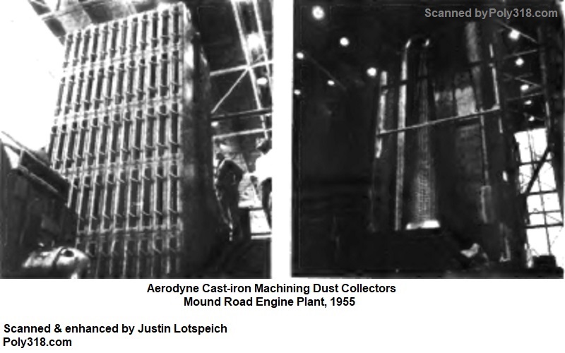
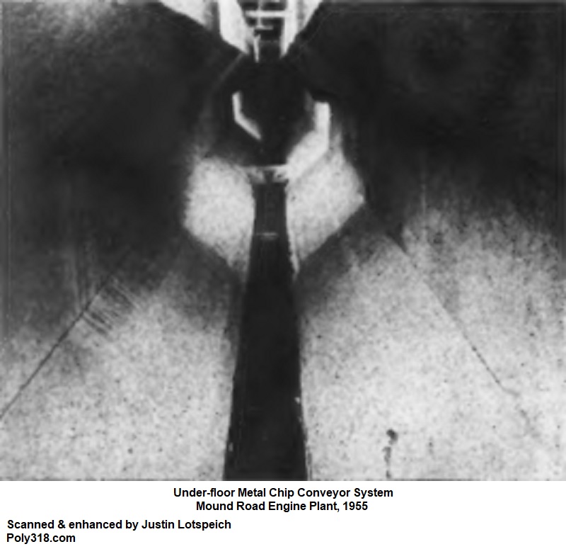
The Plant Engineers devised a system formed into the concrete floor of the plant that collected and transported metal chips, cast-iron dust, steel cutting coolant/lubricant slurry, and other manufacturing debris away from the assembly lines. The underfloor system incorporated air vents and ducts to draw dirty air down via 61 ventilators and Aerodyne dry-type dust collectors that moved, filtered, and returned a staggering 610,000 cfm of air (Figure 4a). According to the design team, the filtered air was tested to be cleaner than the outside air and was revolutionary in protecting worker health and comfort since they did not have to wear respirators.
The cast-iron production machines used slanted collection trays or compressed-air blasting heads to vibrate or blow chips onto 28 conveyor belts running in the underground trenches (Figure 4b). The chips were carried into a 120-ton hopper that dropped them into rail cars to be taken to the foundry for recycling. The steel production machines had an underground pipe system that moved the slurry of machining coolant, lubricant, and steel chips at 12,000 gpm. The slurry was carried into the yard where it was drained, baled, and sent to the rail cars for recycling; the filtered coolant was fed back to the machines through pipes that ran through the underground trenches. According to the design team, the plant used the “largest and most completely automatic, centralized coolant system in the country.” To assist with housekeeping, all independent hydraulic equipment was mounted off the floor above drain pans to allow for easy maintenance so hydraulic fluid would not contaminate the cooling fluid and create slipping safety issues for workers.
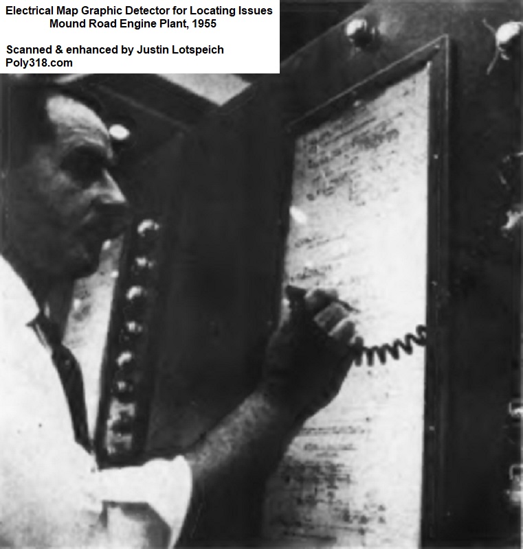
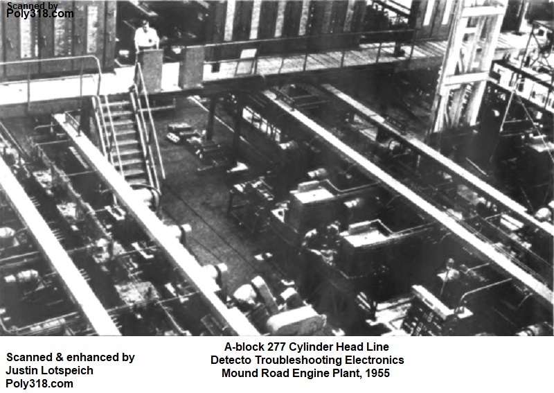
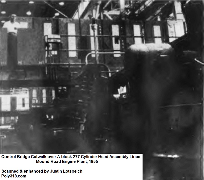
Electrical Troubleshooting System
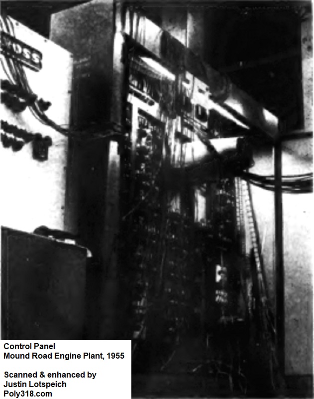
Service Head Dan McCarthy and Tool Trouble Heads Ed McCormick (cast iron section) and John Pietrangelo (steel section) worked with the Master Mechanic team and equipment manufacturer W.F. & John Barnes on a revolutionary new design to plant maintenance and troubleshooting. The electrical systems and hydraulic systems throughout the plant included W.F. & John Barnes electrical “Detecto” panels on overhead bridges at each assembly line that consisted of lit schematics to assist operators in quickly detecting and repairing faults in the machines and circuit breakers (Figures 5a – 5b). According to the design team, this novel electrical system ended up cutting downtime by a whopping 75% compared to the Chrysler, DeSoto, Dodge, and old Plymouth plants.
General Manufacturing Details
The plant employed over 3,000 men and women from supervisors to apprentice production workers all who had never worked in a plant of this caliber and technologically advanced design. The first employees were from the Production Division and handpicked from the old Plymouth plant; they began training in May 1955 just a month before the assembly line pilot started and just three months before the plant had to be under full production. Important supervisors were chosen from a list of those who had already been under consideration for supervisor positions for up to two years prior, primarily from the old Plymouth plant but also from plants across the Chrysler Corporation divisions. Job setters and tool-trouble technicians from the old Plymouth plant with promising expertise were offered foreman positions at the Qualitric plant. Of the entire plant, the majority of production workers were inexperienced, although the design team handpicked highly skilled workers from other Chrysler Corporation plants to run critical lines such as the block boring and honing machines and the crankshaft lapping machines.
The original team of foreman spanned the areas of tool troubleshooting, electrical maintenance, hydraulic maintenance, and machine repair, and they were trained on the prototypes of the novel equipment and systems at the equipment manufacturing facilities as the very machines were under production so they could become intimate with the equipment before they were even installed in the Qualimatic plant. This core group of foremen would go on to rotate training on all the machines in the plant once they were installed and operational until they were skilled on every machine. The purpose of this hands-on rotation education was twofold: first, the foremen would have plenty of time with the equipment and the assembly line to provide troubleshooting feedback to the design team in order to work out design and teething problems; second, the foremen would train the thousands of inexperienced production workers in a razor-tight one month deadline to prepare for the pilot goal of 50 engines per hour by August 15, 1955 on the way to full production of 150 engine per hour by October 15, 1955.
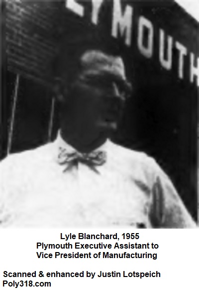
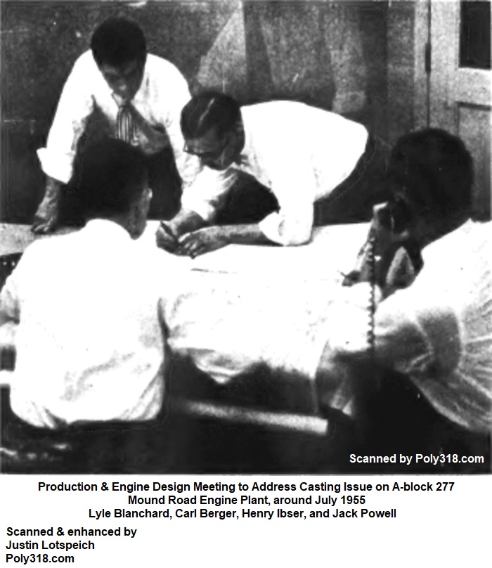
While equipment companies were still designing and manufacturing equipment, Plymouth began stockpiling machining and cutting tools, castings, forgings, and raw materials required so pilot production could start at each assembly line as soon as the suppliers delivered equipment and the plant engineers and construction workers installed them. While plant engineers, foremen, operators, and production workers began piloting the assembly lines as they came online, the design team coordinated with the engine designers and casting-process designers to work out issues as they arose. The design team claims that there were very few issues needing addressing in the parts casting process due to the quality of the original blueprints. One such issue was with the cylinder heads. According to Executive Assistant to the Vice President of Manufacturing Lyle Blanchard, “The spider webbing in the water flow chambers was too narrow in sections and had to be opened up for the maximum cooling of an operating engine. To insure [sic, misspelling] the highest quality and consistency in casting, the technical specialist worked with Planning, going over every aspect of the casting operation checking for the best location of sprues, control of cooling, etc. By coordinating so closely with Planning, only minor problems in this area have occurred since going into production.”
General Receiving and Shipping Departments
The General Receiving Department was an area of 400 sq.ft. and consisted of nine truck docks, one rail receiving dock, and one rail shipping dock. Purposeful by design, very few incoming materials were ever stored on site in bulk, but, instead, the General Receiving immediately placed received materials onto the production lines to form a smooth loop of incoming materials and outgoing engines. The individual parts lines ran east to west, and these finished components were fed into the larger final assembly line that ran south to north.
Block Production
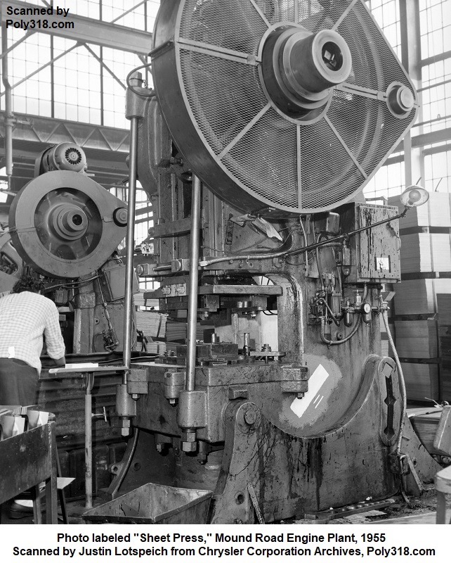
The design team debated whether the engine blocks should be broached or milled. While broaching was the faster method, it had drawbacks often in the form of broken and worn cutters due to the nature of the hydraulic broaching process coupled with the metallurgy of the cast-iron being machined. Broaching also placed greater forces on the block than milling, requiring that the block be structurally stouter so it would not distort during broaching. At the time, milling technology had advanced greatly to where some on the design team thought it was a viable option. A major drawback to milling even with the advancement was the need for eight mills to handle the goal of producing 150 engines per hour compared to needing just two broaching machines. Six more milling machines meant less floor space and more equipment to maintain without a significant enough benefit over broaching, so broaching was the winning design.
Crucial to all the machining processes, the Master Mechanic’s team worked with the Engine Design team to incorporate indexing pads into the block design, which are the different rectangular pads and flat pads on the block. The different machines used the pads to index and clamp the blocks to maintain extremely consistent tolerances. Down at the engine assembly line, the pads provided the key to mechanization of those processes as well.
The next obstacle to tackle was the broaching hydraulics. Conventional block broaching machines used hydraulic fluid that would always be contaminated with some form of air and water to where the fluid on such heavy hydraulic systems would compress and cause the rams to chatter, harming the finish quality. This chattering also dulled and broke tools and placed more wear on the machines. To resolve the hydraulic issues, the designers worked with the equipment manufacturers to use more simplistic electro-magnetic mechanical drives. The specially designed machines also surpassed their predecessors by being able to take off up to 1/4″ of casting material compared to the 1/8” allowed by conventional broaching machines. The Master Mechanic’s team and Engine Designer teams sorted the last consideration by beefing up the block in order to withstand the 1/4″ broaching forces without distorting, which is one reason the A-block engine block and heads are slightly heavier than the future LA block (the rest of the weight difference largely comes from the A-block having thicker cylinder walls).
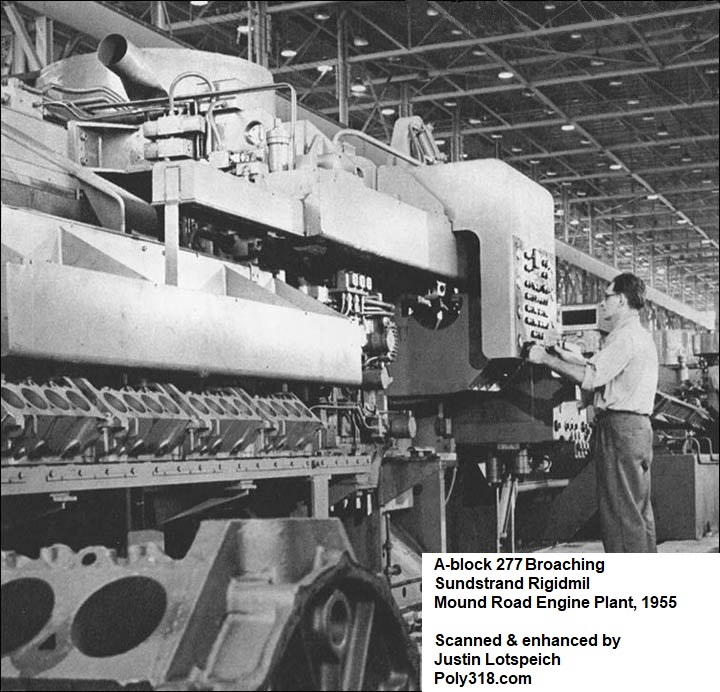
The rough block castings were transported from the Receiving Department on the overhead conveyor system into a pair of the specially designed tandem Cincinnati automatic two-stage broaching machines equipped with Sundstrand Rigidmils (Figures 6a – 6b). The tooling included hundreds of individual teeth tipped with Wessonmetal set in quick-change sections for ease of switching out the cutters. The block was broached on the top of the end rails and on both cylinder bank decks using a 23″ stroke at 150 FPM. On the return stroke, the machine broached the oil pan rail of the next block. As the block passes into the second broaching machine, the bellhousing face of one block and the front face of another block were broached in one pass of the ram.
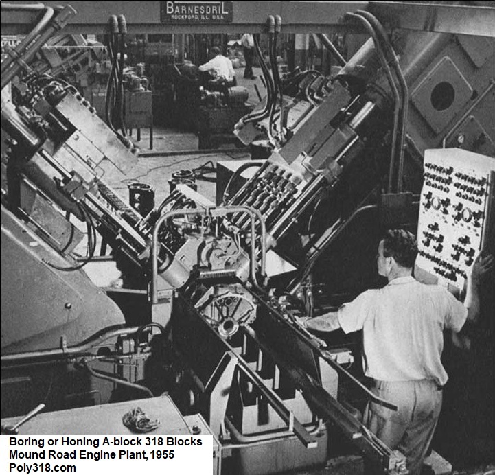
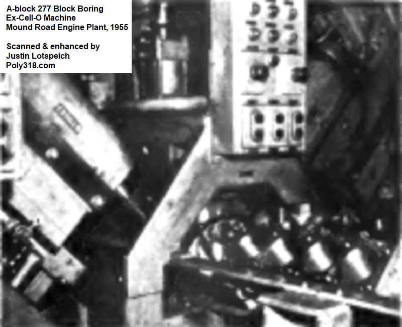
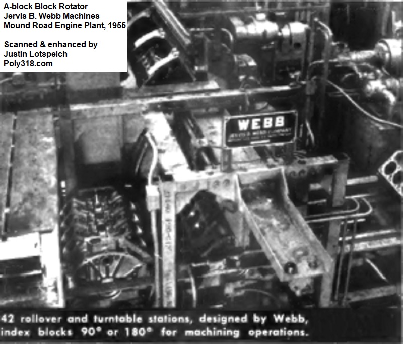
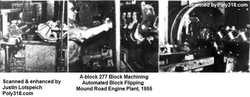
The broached blocks received main caps and bolts that had been processed in another section of the line and moved down to Greenlee and Barnesdril boring machines that rough-bored the cylinders two at a time per bank (four cylinders per cycle) in order to remove chattering caused when boring only one cylinder per bank (Figure 6c). The rough-boring removed approximately 0.100” of material. From these machines, the blocks passed into an Ex-Cell-O boring machine that semi-finished the cylinder bores, again, two cylinders per bank at a time to eliminate chatter (Figure 6d). As the Ex-Cell-O machined the cylinder bores, it also machined the camshaft bearing lands and the crankshaft main-journal lands (Figures 6e – 6f). Automated into the machines, the block was rotated as needed to align with the tools to expedite the process and remove the need for unclamping and re-clamping the block (Figure 6g).
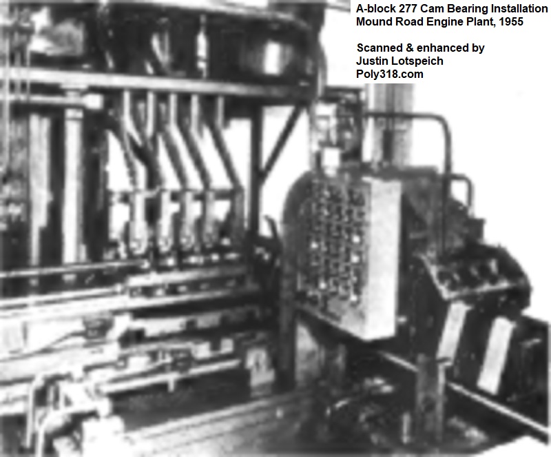
The blocks moved to an Apex cam-bearing assembly machine (Figure 6h). The different-sized camshaft bearings gravity-fed from hoppers, rolled in a fixture until the driving head’s pin indexed in the oil hole(s) to properly position them for installation, were picked up in sets of 5 by a collapsible mandrel, and were pressed into the block (Figure 6i).
Next, the blocks met what the designers described as the piece de resistance of the block line—three novel Ex-Cell-O four-way precision boring machines designed for the A-block and Qualimatic plant (Figure 6j). The machine clamped the block to a moving pallet and performed multiple operations that used to require a handful of different machines and clamping and unclamping the block in each machine, thus introducing tolerance stacking and production delays. The block was machined on all four sides simultaneously. The camshaft bearings were finish-honed. The crankshaft main journals (without bearings installed) were finish line bored; the two bellhousing alignment dowel-pin holes were drilled and countersunk; the oil galleries were drilled and bored; the oil-pump mounting pad was milled; the intermediate shaft bushing hole was bored; and the large hole for the distributor body was bored.
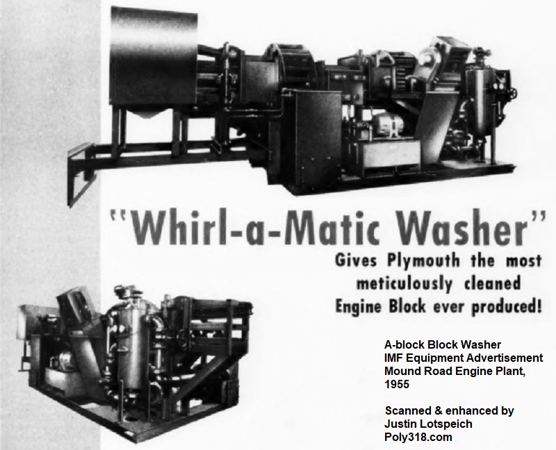
Next, the blocks ran through an IMF “Whirl-O-Matic” washer for cleaning (Figure 6k). The machines were specially designed for the A-block with rotating stations and high-pressure jets aligned with critical parts of the block such as oil galleries, lifter bores, etc. After washing, the blocks were dried at a station with 20,000 CFM blowers. This cleaning process alone was revolutionary in that the blocks were better cleaned than any previously mass-produced engine and set the standard for assembly plant cleanliness moving forward.
Cylinder Head Production
The cylinder-head line was made up of four parallel lines consisting of multi-station transfer machines that measured 420’ long. The line began in a single series of tandem broaching machines. After the broaching machines, the line branched into four separate lines in order to synchronize the many different types of machining required to limit downtime for tooling changes and repairs. Each line had a master control panel mounted to a bridge that ran above the sections and allowed two operators to shift heads from one line to another as needed during shutdowns and to adjust the line speeds as needed so that when one line stopped the remaining lines could continue processing heads without jamming up the entire process (Figures 7a – 7b). These master control panels also included the electrical W.F. & John Barnes “Detecto” panels designed specifically for the Qualimatic plant that consisted of lit schematics to assist the operators in quickly detecting and repairing faults in the line.
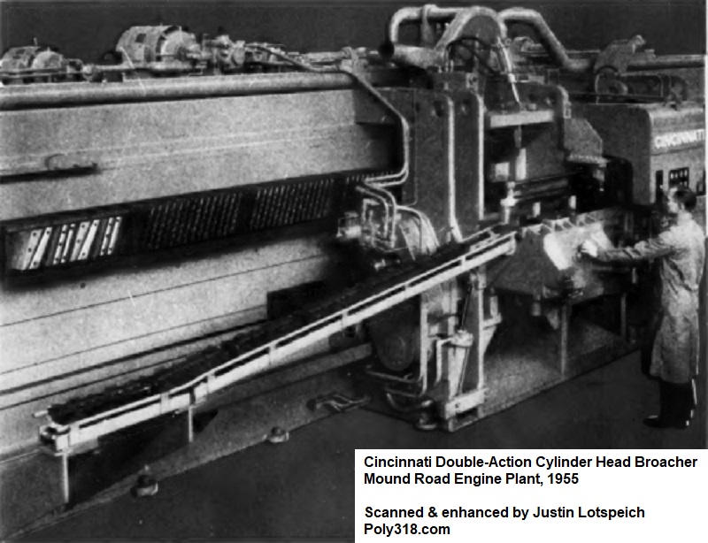
Casting blanks were brought to the line from the Receiving Department via a conveyor system. Using hoists, production workers manually loaded the castings into a series of Cincinnati horizontal surface broaching machines that broached multiple surfaces including the deck, intake-manifold flange, exhaust manifold flange, the ends, and the sides of the rocker-shaft lands(Figure 7c). As the heads automatically moved through the different machines, a W.F. & John Barnes Company conveyor system rotated and flipped them as necessary to align with the multiple tools.
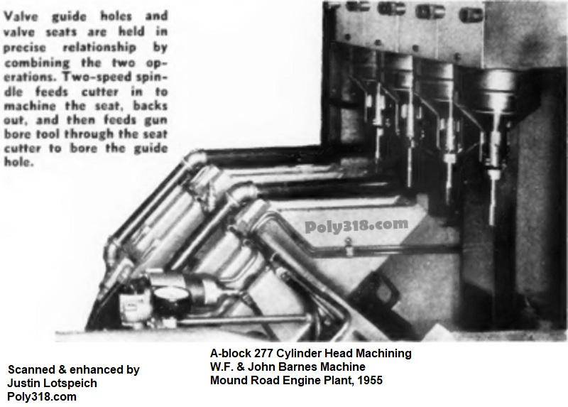
An issue that plagued cylinder-head production prior to the A-block and Qualimatic plant, one machine was needed to bore the valve-guide holes and another machine to machine the valve seats. Having to clamp, unclamp, and reclamp the head for both machines made the critical alignment of the seat to the guide extremely problematic and slow. The design team decided to solve the problem once and for all by working with W.F. & John Barnes Company to develop a single machine that would clamp the head and machine both the valve guides and seats in one go without having to unclamp and reposition the head (Figure 7d). In this machine, the head was clamped down, a circular carbide cutter plunge-cut the valve seats, and another tool gun-bored the valve guide holes. The machine held run-out tolerances at 0.0005”, which was far tighter than the industry standard of 0.003” – 0.004.” If the run-out exceeded 0.002”, the machine automatically shut down and prompted the operator with a light to diagnose and correct the issue.
A series of other machines bored the rocker shaft lands, milled the valve-spring pads, and drilled and faced the pushrod, oil drain-back, rocker shaft lock, and mounting bolt holes. A machine drilled and tapped the intake manifold, exhaust manifold, and valve cover bosses, which would later drill and tap the accessories holes when they were introduced in 1961.
Once all machining was completed, the heads moved through an Apex automatic air-leak testing machine equipped with a Moore differential-pressure system. Heads that passed testing moved down the assembly line to receive valvetrain; heads that failed the leak test were automatically marked by the machine with a specific-colored paint that identified to the operator the location of the leak. These “leaker” heads automatically moved to a water-testing machine where the operator pressurized the jacket/runner with water and checked for leaks. Heads that passed this water-leak inspection were placed back on the line, while leaking heads would be sent to the scrap rail cars for recycling, although these failures were rare due to the quality of the casting and machining processes.
Connecting Rod Production
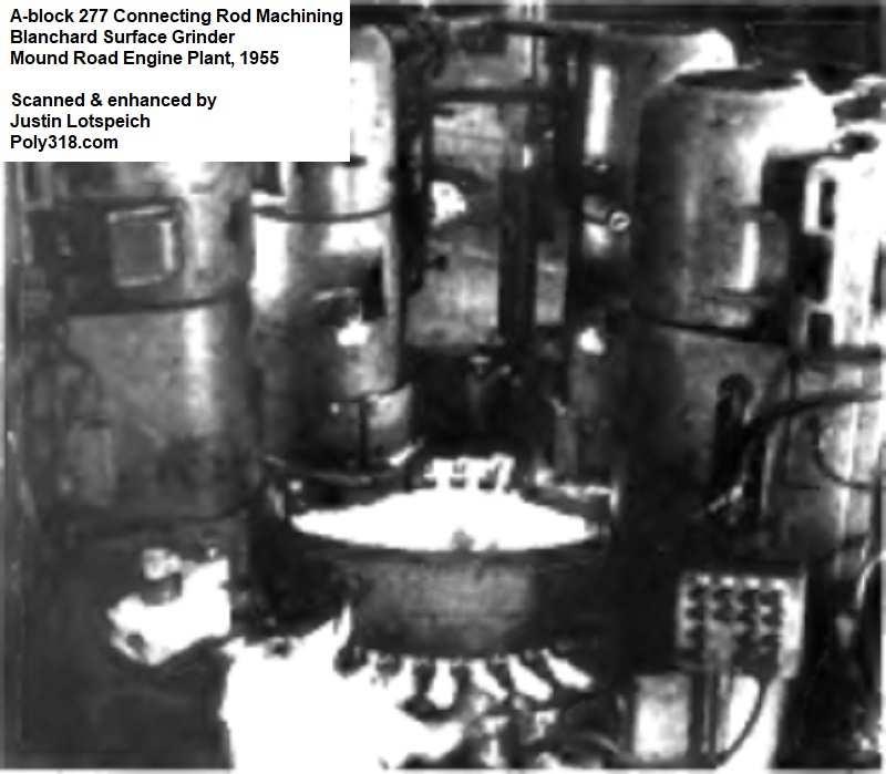
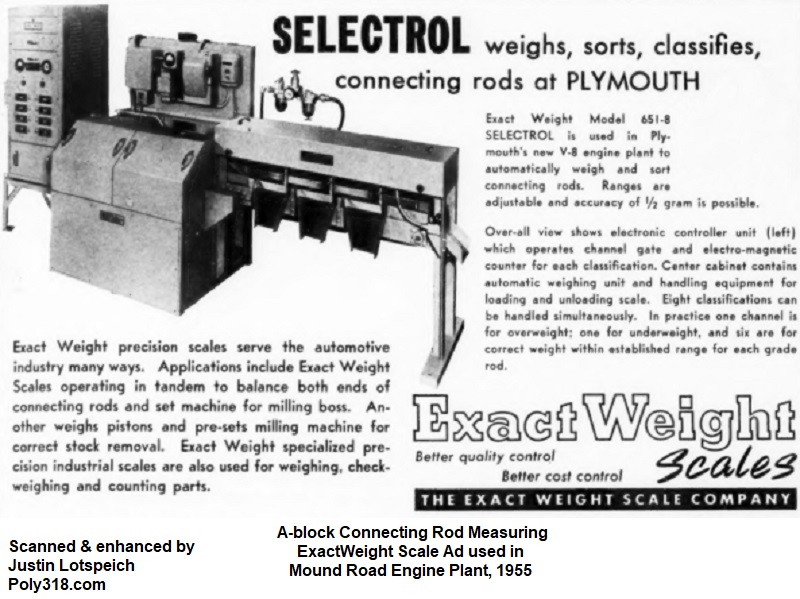
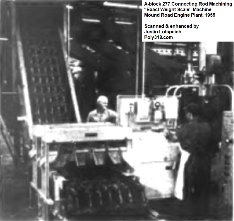
The connecting rod forgings made their way into a Blanchard four-wheel, vertical-spindle automatic surface grinder where the rods were shaped on the outside within 0.0001” of an integral form gauge (Figure 8a). From that machine, the rods ran through a washer and to a Morris “Exact Weight Scale” (Figures 8b – 8c). The machine automatically sorted the rods into six weight groups that fell within tolerance, one group that was below tolerance, and one group that was above tolerance. The six weight groups within tolerance were sent in matched groups to a hopper that fed a broaching machine. The group of rods that were overweight were sent for additional machining. The group of rods that were underweight were sent to the scrap rail cars for recycling. The forging and machining processes were extremely accurate to where under and overweight rods were uncommon.
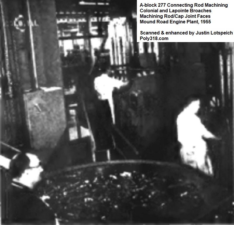
Two Colonial 15-ton 66” stroke, vertical dual-ram broaching machines processed the joint faces of the rods and the half-round for the bearing. The rods were then loaded by hand, due to their awkward shape, into a Lapointe vertical dual-ram broaching machine that processed the bolt bosses (Figure 8d).
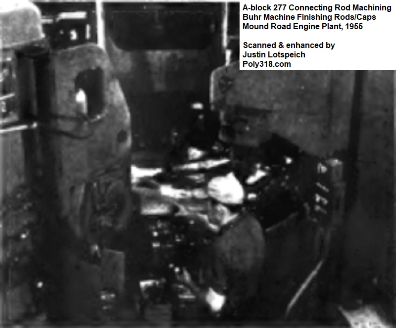
At the next station, operators fed the rods into a Buhr dial-index machine that drilled the wrist pin holes, rough-reamed them, and chamfered the openings (Figure 8e). The rods were automatically ejected from the machine and conveyed to a Blanchard two-wheel automatic surface grinder that finish-ground the rod-to-cap joint face.
The rods moved into a series of Buhr dial-index machines that drilled, chamfered, and reamed the bolt holes, milled and chamfered the bearing lock slots, milled the oil groove, and spotfaced the bolt bosses (Figure f).
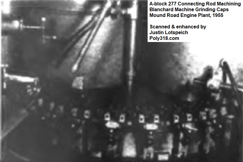
In another area on the line, the connecting rod cap forging began processing in three Lapointe horizontal continuous broaching machines. The first machine broached both sides of the caps in parallel; the second machine broached the bolt bosses and nut seats; the third machine broached the joint face and half-round for the bearing.
The caps moved into a Blanchard surface grinder where the joint faces were ground (Figure 8g). From this machine, the caps loaded into a Buhr dial-index machine that drilled, chamfered, and reamed the bolt holes. The machine milled and chamfered the bearing lock slots. A second Buhr machine spotfaced the caps.
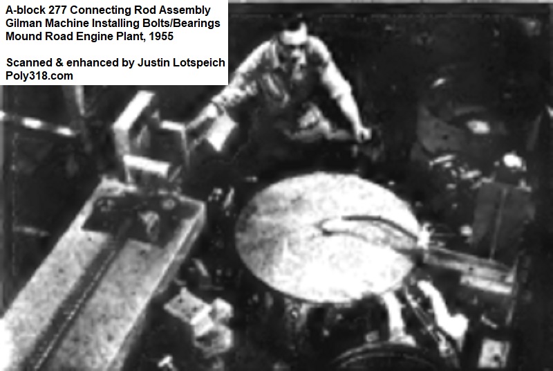
The machined rods and caps were conveyed to a revolutionary Gilman “Indexomatic” machine built specifically for the A-block and Qualimatic plant (Figure 8h). This single machine assembled the rod, caps, bolts, and nuts. The rods and caps automatically fed from hoppers and indexed into a turret. The oiled bolts fed from a hopper into the rods and were pressed in. The cap was automatically inserted over the bolts, and the nuts fed from a hopper into automatic air-wrenches were torqued to 45 lb.ft. specification. After passing the machine’s gauges that checked for proper orientation and tolerances, the rods were ejected. Rods that passed inspection moved down the conveyor, while failed rods moved to another area for inspection.
The rod assemblies made their way into a Blanchard surface grinder that faced both ends of the rod. They moved into a Rehnberg-Jacobson automatic indexing machine where hopper-fed bronze wrist-pin bushings dropped over a mandrel, and the bushings were pressed into the rods. The machine then indexed the rods and burnished the bushings before chamfering the openings to 0.020” x 45°.
The rods automatically fed into a Motch & Merryweather weight mill equipped with Toledo balance scales. The machine identified how much weight would need to be removed and from what locations to balance the rod. A twin-head Wesson Rigidcut mill incorporated into the machine performed the material removal.
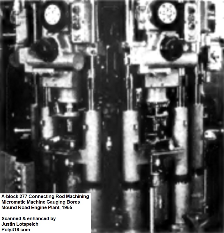
An Ex-Cell-O boring machine finished the wrist pin and crank holes before a Sheffield gauge machine measured the diameters. With the help of a Lectrolair unit, the machine would shut down and illuminate a series of indicator lights if a rod fell outside of tolerance, which was rare. The type of lights would tell the operator if the rod holes were undersized or oversized. Rods that did not pass the inspection were sent back for additional machining to bring them within tolerance or to the scrap rail car for recycling if they could not be corrected.
One last machine, a newly designed Micromatic “Turret-Hones,” used six spindles mounted on a rotating table to machine the crankshaft journal bores round and straight (Figure 8i). The collapsible honing heads were preset to a specific diameter. The operator loaded the rods onto the table, the table automatically rotated to align the rods with the honing heads, the table rose to insert the rods into the spinning honing heads, and the hones expanded and machined the rods until reaching the preset diameter. The operator unloaded the rods manually.
The rods passed into a Trio Tool Company stamping and disassembly machine. The crankshaft bore slid over a rod, and an indexing head loaded with eight pairs of dies from 1 through 8 stamped a set of eight rods and caps. The machine passed the rods into a second station where the rod and cap were clamped independently. A set of air wrenches unscrewed the nuts a preset number of turns, and the clamping tables separated the cap and rod to prepare them for cleaning, oiling, and eventually receiving the bearings. Another Trio Tool Company assembly machine installed the piston and oiled wristpin onto the rod and secured the locks to finish the connecting rod line.

Piston Production
The piston line used many machines Plymouth used in its old engine plant but added robust automation to the process. A rubber conveyor belt ran the length of the line, transporting the piston castings from the Receiving Department through the different machines. The system used a series of elevator conveyors to raise and stack pistons at the different machines along with chutes to unload them from the machines via gravity. The automation allowed the line to run constantly with machines automatically loaded and unloaded versus requiring operators to manually load and unload pistons. By automating the system using gauges at each machine, the system would be automatically shut down if five pistons in a row fell out of tolerance to allow inspection by an operator. The most common reason for such shutdowns was tool wear requiring a change-out.
An interesting production fact I found in reading the designers’ articles and essays is how the conveyor system modified the piston design. Traditionally, pistons of the era had two flat sides, which many modern aftermarket pistons have. This design made it impossible for the pistons to roll on their sides and for conveying machines to easily index the pistons radially. The Master Mechanic’s team in working out the design of the conveyor system approached the Engine Design team and asked them to design a rim around the bottom of the skirt allowing the pistons to roll on their sides down the gravity chutes of the conveyor system. The Master Mechanic’s team also had the Engine Design team include a notch in this rib that the machines would use to both trigger limit switches and index the pistons radially (Figure 9a). Now you know why the A-block piston has a continuous rim and index notch on the bottom of the skirt.
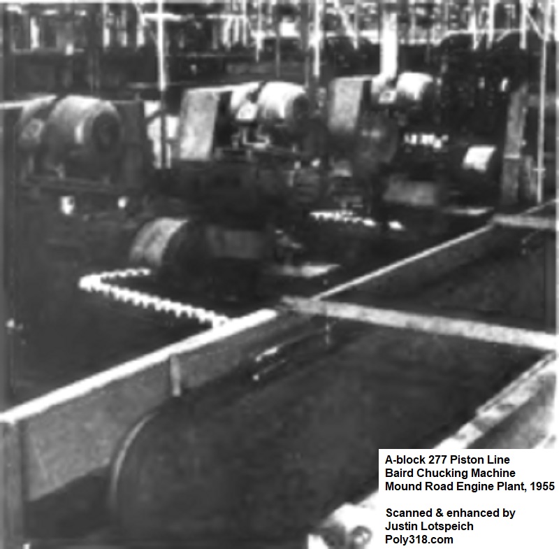
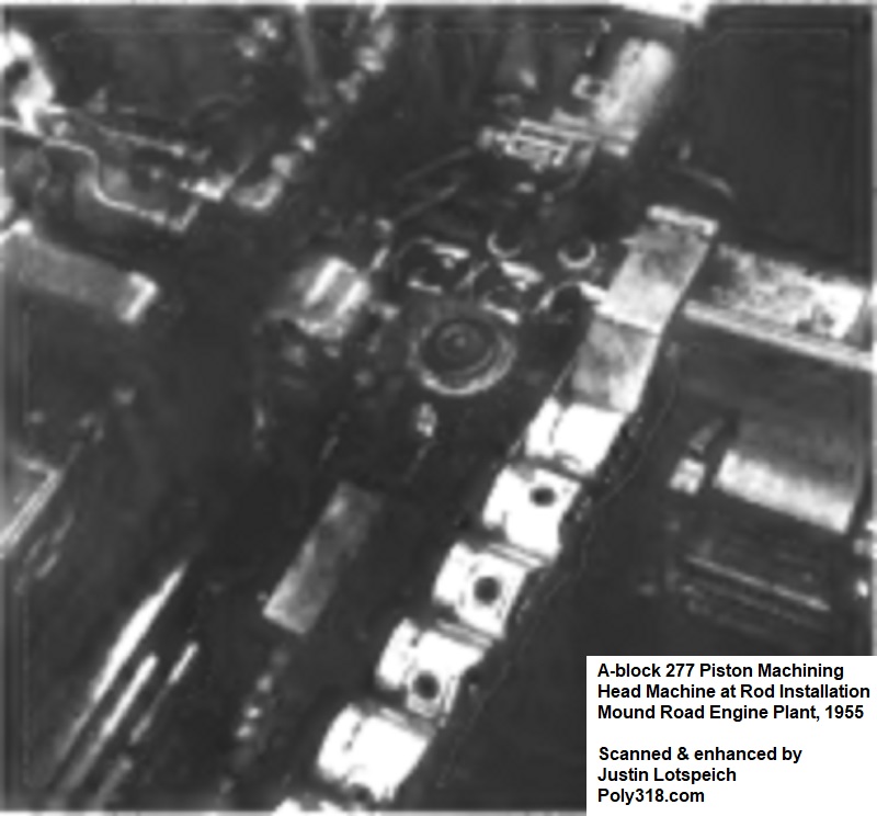
The line started with four Baird six-spindle chucking machines that processed one piston in 7.93 seconds (Figure 9b). The machines rough-turned and finish-turned the ring lands, semi-finished the skirt O.D., and finish-turned the ring grooves. A Cincinnati grinder handled machining the piston skirts with the help of a Federal electronic gauging head.
The pistons then passed into four Heald “Bore-Matics” mills for milling the oil slots through the oil-ring groove. After the milling, the pistons moved to five Heald double-end “Bore-Matics” where the wrist-pin holes were rough-bored, grooved for locks, chamfered, and checked with an air gauge. The pistons moved to three Heald “Bore-Matics” that cut the two valve reliefs. From there, the pistons entered a group of Heald “Bore-Matics” equipped with Pratt & Whitney “Air-O-Limit” gauges to finish-bore the wrist-pin holes.
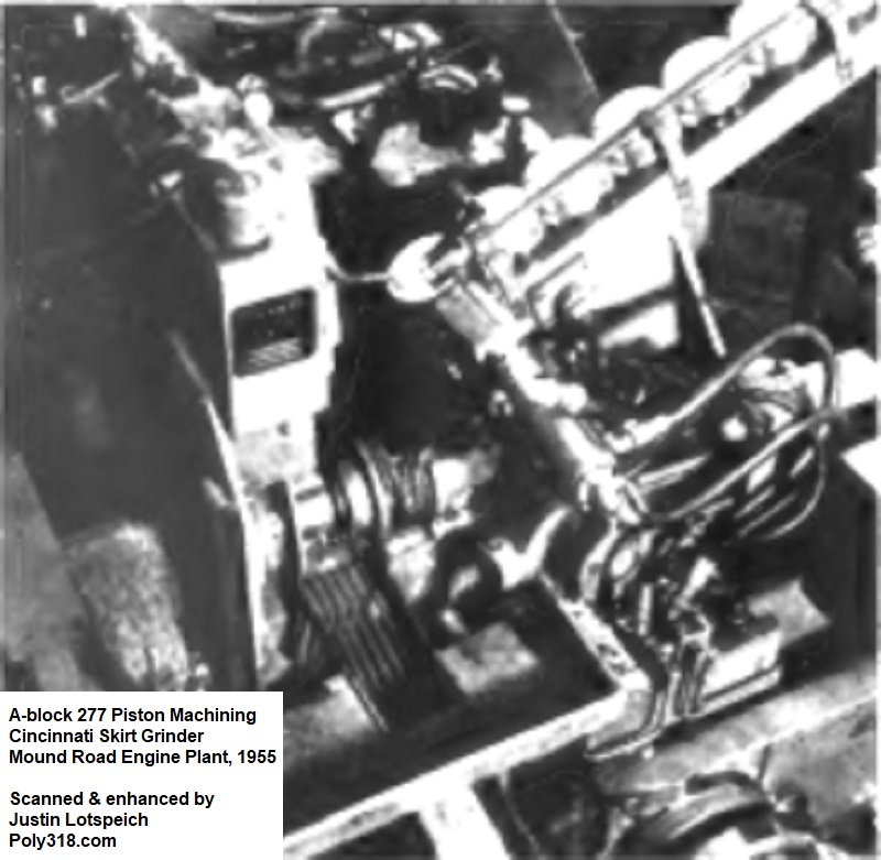
The pistons went through a group of 13 Cincinnati skirt grinders specially designed for the A-block pistons (Figure 9c). The designers chose to grind the skirts rather than mill them as was the conventional method because the industry had issues with setting and keeping tools properly set, tool breakage, and tool wear due to the unique shape of pistons, the aluminum alloys, and quality of casting used for pistons at the time. Using the novel grinders for this operation resolved all these issues and provided superior accuracy in finishing the skirt.
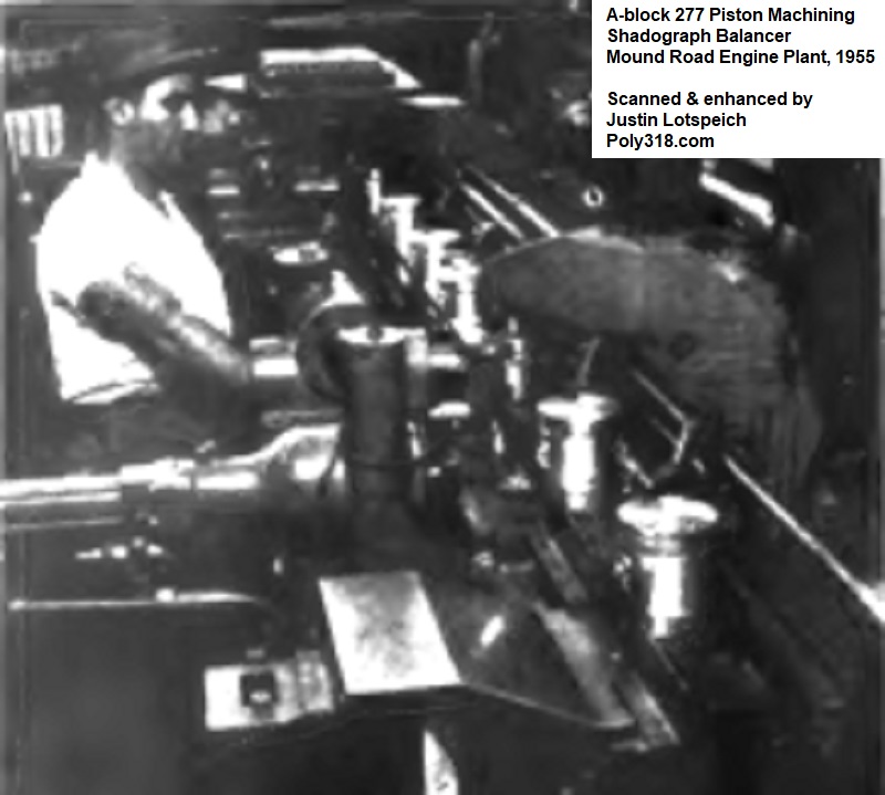
After machining, the pistons entered three Morris “Exact Weight Scale” mills equipped with Shadograph moment-balance scales that pinpointed how much material required removing and at what locations (Figure 9d). The same machine removed the appropriate material to balance the pistons.
Finally, the processed pistons went through Frederic B. Stevens automatic washers and driers. The finished pistons entered Sheffield automatic gauging and classifying machines that checked ring grooves, ring lands, wrist-pin holes, skirt diameter, and stamped the pistons “A,” “B,” “C,” “D,” or “E” depending on the measurements. The pistons left the machine in groups based off the letter stamp bound for the connecting-rod assembly line (Figure 9e).
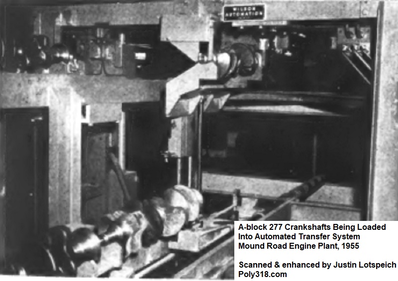
Crankshaft Production
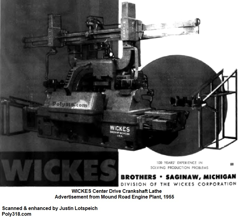
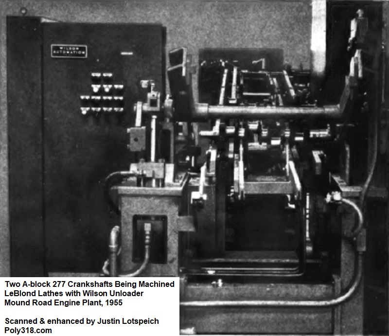
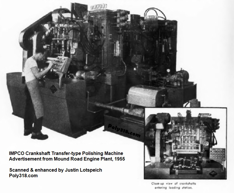
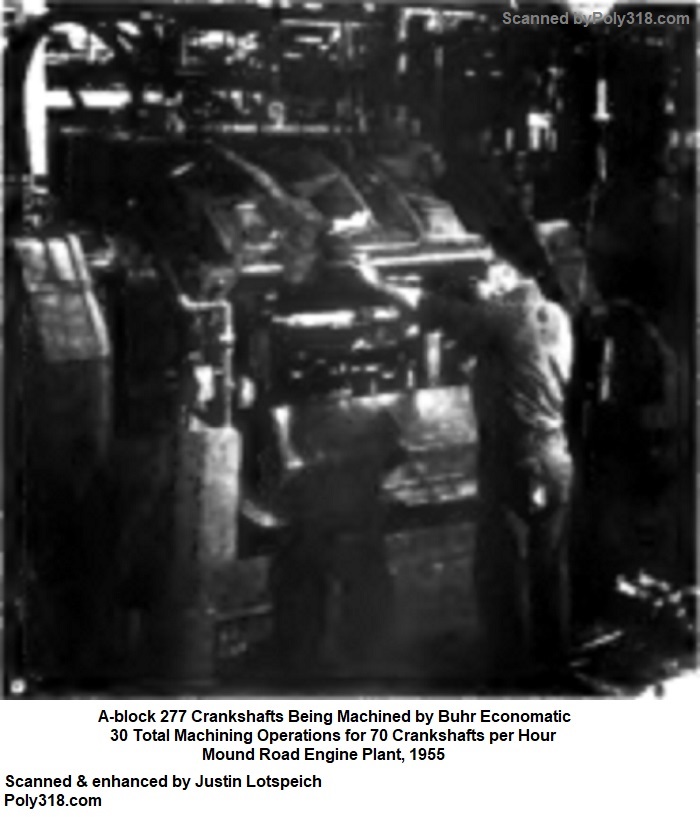
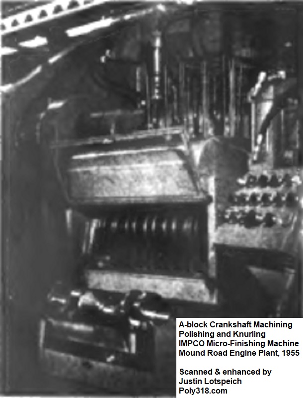
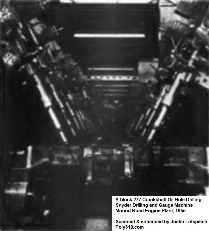
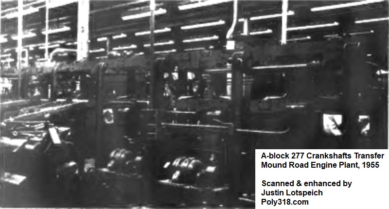
The crankshaft line was the most complex line and consisted of 65,000 sq.ft. of operation area that housed the largest quantity of different machines for a single line at 107 machines. The line included Crankshaft Machine Company lathes; LeBlond lathes; Seneca Falls “Lo-Swing” lathes; Wickes lathes; Cincinnati grinders; Landis grinders; Fitchburg crankshaft mills; Ex-Cell-O boring machines, Snyder oil-hole drilling machines; Buhr “Economatics” drilling machines; Olson balancing machines; Impco crankshaft straighteners, washers, polishers, and demagnetizers; Wilson double-positioners for machining two crankshafts simultaneously; a series of Sheffield automatic air-gauging stations, and other equipment (Figures 10a – 10i).
The crankshaft machining is yet another example of how the A-block design team sought out collaboration from every aspect of the engine, processing, and plant design including getting equipment manufacturers to design and build one-off machines that relied on other suppliers’ equipment, some of whom were competitors such as those who supplied the multiple crankshaft lathes. Rather than contracting one equipment manufacturer to provide all the necessary lathes, the design team chose manufacturers for their strengths and through a shared goal of producing the most sophisticated engine plant got the manufacturers to work together.
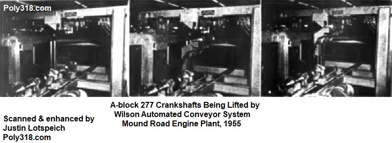
The 4,500’-long Wilson automation loader, unloader, and conveyor system was at the heart of keeping the crankshaft line moving. It was made up of 385 individual units controlled by 144 electrical panels that coordinated the automation and allowed the system to automatically slow and increase speed as necessary to handle the crankshaft workload and any issues with machines such as broken cutters/bits. The system used four types of handlers including those for broadside transfer load and unload; lengthwise transfer; turntables; and elevators. According to Plant Engineer William Allen, the designers chose to implement the complicated automated conveyor system not to eliminate production workers for the sake of saving money on labor but to spare them the physical labor of transporting the crankshafts that traditionally had been one of the most laborious lines in an engine plant that saw higher rates of worker fatigue and injury than other lines due to the heavy weight of the crankshafts and their awkward shape that stressed the wrists, hands, and back. Allen tells a story of a journeyman crankshaft grinder with 23 years of experience at the old Plymouth engine plant applying for a position at the new A-block Qualimatic plant who specifically told the hiring agents he did not want to grind crankshafts any longer and asked to be trained on a different line because his body was wearing out from handling the crankshafts. The hiring agent took him around to the new crankshaft line with the automated conveyor system, and the crankshaft grinder marveled at how better it was for the operators and other production workers. No longer having to labor just to get the crankshafts in position for him to complete his work, he changed his application and ended up becoming one of the first A-block crankshaft grinders at the Qualimatic plant.
Camshaft Production
Camshaft production began with operators hand-loading blanks into Rehnberg-Jacobson one-way, horizontal, six-station automatic index trunnion machines that automatically clamped them. The machine drilled, countersunk, and reamed a hole at the ends for future indexing before ejecting the blanks. The blanks moved to a set of tandem automatic Seneca Falls “Lo-Swing” lathes where the bearing journals and intermediate-shaft gear were rough-turned, finish-turned, and faced in increments starting in the first machine in preparation for future grinding. The blanks were automatically ejected, run up an elevator conveyor, gauged using a Sheffield air gauge, racked in a column, and dropped into the second machine that performed any additional machining on the journals and gear turning and facing based off the Sheffield gauge results.
Next, the blanks moved to Impco 22-ton hydraulic machines that straightened them within tolerance before passing them to a bank of Landis camshaft grinders. The Landis grinders rough-ground the bearing journals and finish-ground the gear diameter. Moving along to another series of Landi grinders, the bearing journals were finish-ground.
The blanks moved to feeding racks where a production worker loaded blanks into series of four Norton Cam-O-Matics machines that rough-ground the intake and exhaust lobes before moving the blanks to four Landis grinders that finish-ground the lobes. Next in the line, four semi-automatic Landis grinders faced the number 1 bearing end and gear for thrust tolerance.
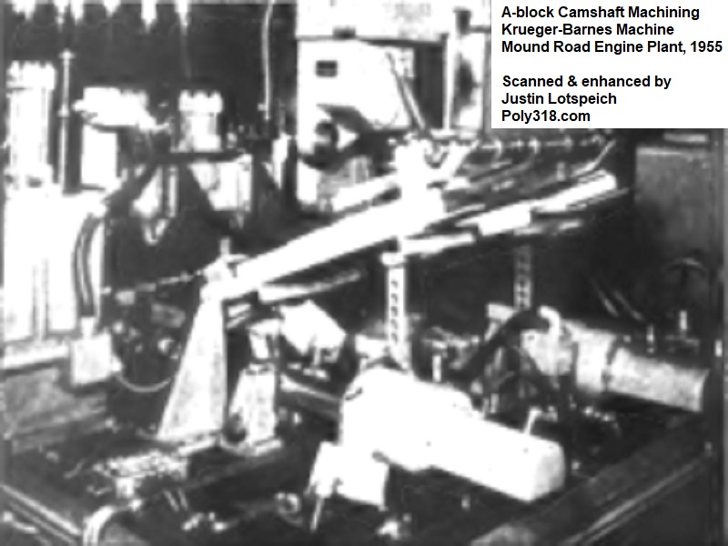
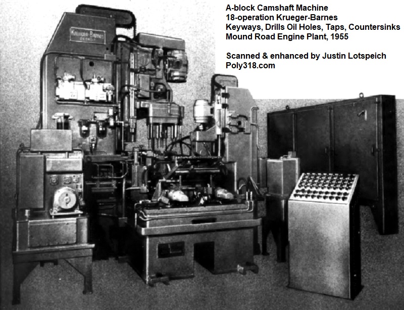
The camshafts passed to one of two Krueger-Barnes seventeen-station transfer machines (Figures 11a – 11b). Due to the delicate handling required to protect the finished journals and lobes, the camshafts were handled by operators who loaded them into specially designed protective racks from which the machines fed. The machine drilled the oil holes; drilled, counterbored, reamed, and tapped the sprocket bolt hole; and milled the sprocket Woodruff keyway.
Next, a Lees-Bradner vertical six-spindle machine hobbed the gear teeth. The gear was inspected by an Airborne Instruments Laboratory gauge for growth that may have occurred during machining. If the gear was outside of tolerance, the machine automatically adjusted and made another pass. From this station, the camshafts went through another Impco hydraulic straightening machine followed by a Bilt-Rite wire-brush machine.
The final stages of machining occurred on a series of Landis grinders that put the final finish-grind on the main journals followed by a series of Schraner machines that lapped the lobes and journals. The camshafts were checked using a series of Carl Zeiss Jena micrometers (Figure 11c). The finished camshafts were sent through a washer and drier and down the conveyor where they would be organized on trays with the lifters and pushrods as the units made their way toward the engine assembly line.
Oil Pump Housing Production
The oil pumps were one of the more difficult parts to process due to their small size, awkward shape, and many holes and bores on different geometric planes. Prior to the A-block engine, engine oil pumps conventionally required seven different machines to process, which took time, equipment, tooling maintenance, and led to issue with tolerance stacking. The Master Mechanic’s team worked with the Engine Design team to create a pump housing that could more easily be processed with fewer machines, including specific transfer ribs for the machines to use for indexing and transferring.
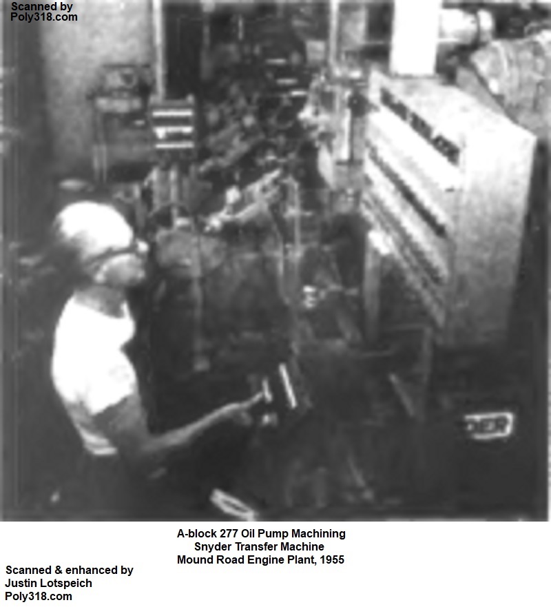
An operator inserted a rough casting into the index machine and manually started the process via a button. When the process finished automatically, the operator removed the housing and installed it in an adjacent transfer machine and started the process. The operator repeated this process moving between both machines so that neither was ever empty. The next machine, a Snyder dial machine, milled the cover face and transfer ribs that the Master Mechanic’s and Engine Design teams had designed into the casting (Figure 12a). The housing automatically moved from this machine via a beam conveyor through the different stations in the same machine that made a total of 49 machining passes on the housing all without having to unclamp the housing.
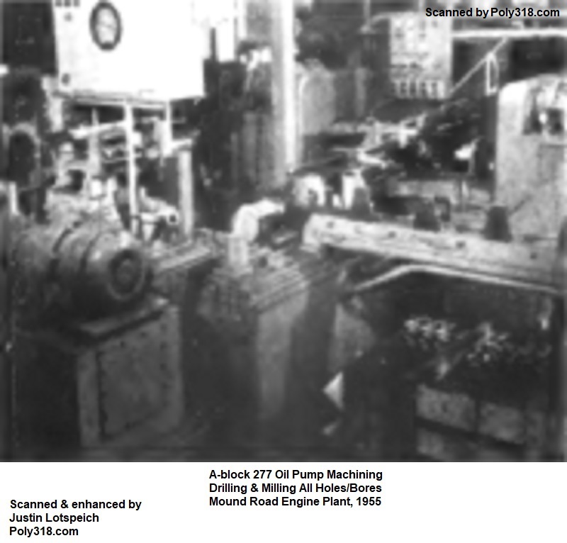
The housings moved into a Beach automatic air-leak tester. Those that passed went into one of three Ex-Cell-O transfer-type precision boring machines (Figure 12b). The machine turned the snout that locates into the rear main-bearing cap, rough and then finish-bored the rotor chamber, rough and then finish-bored the rotor shaft hole, milled the cover face, and milled the mounting pad. The housing passed through a washer before moving to the assembly line where it received the rotors, pressure-regulator parts, and cover.
Rocker Arm and Shaft Production
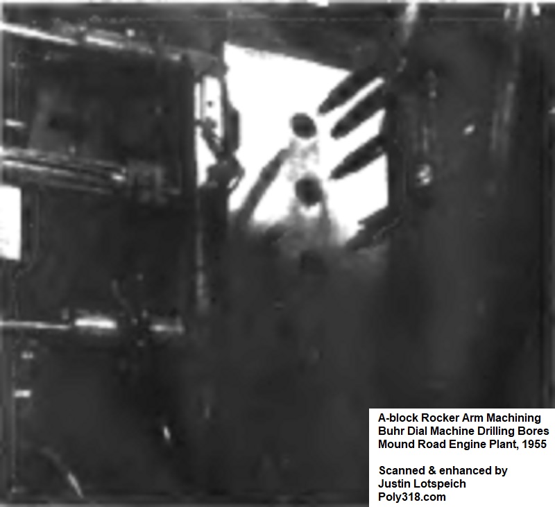
The rocker-arm castings were placed into a series of machines that faced them, bored and countersunk the shaft holes, and ground the tips. Information on these specific machines is not covered in any documents I have found aside from the Buhr machine used to bore the shaft oiling holes and bolt notches (Figure 13a).
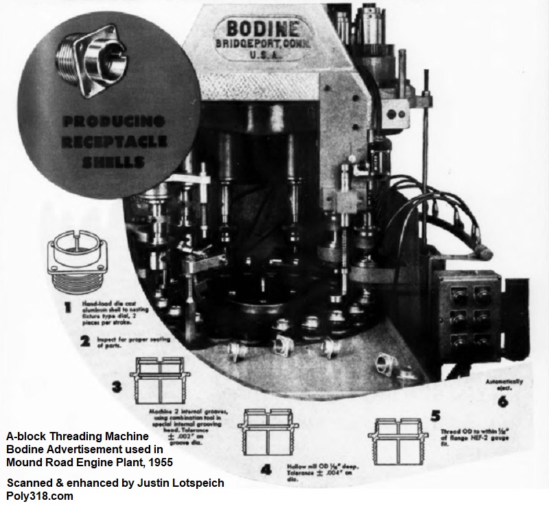
Two Bodine dial-type automatic tapping machines handled the rocker-arm adjusters and other fasteners (Figure 13b). Due to the awkwardness of the rocker-arm shape, they were placed by hand two at a time into the machine that secured them and performed the machining. A Syntron vibrator feeder supplied the adjuster screws via a hopper. The machine inserted and screwed the adjusters in a single turning action to a preset depth, thus setting the valve lash that would later be checked during engine assembly.
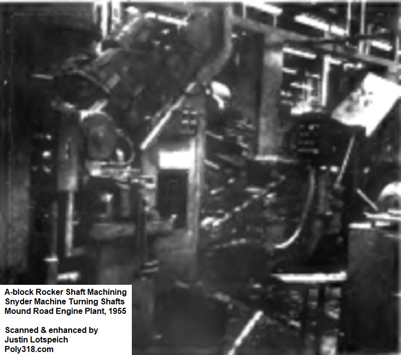
The steel rocker-shaft blanks were sent through a straightening machine. A mill handled the different notches, holes, and oil grooves. The shafts moved into a Snyder lathe that finish-turned them before they were lapped by another machine (Figure 13c). Finally, after the shafts went through a washer, expansion plugs were gravity fed from a hopper into a press that plugged the ends.
Intermediate Shaft Production
While details about all the machines don’t exist, the intermediate-shaft blanks were run through a series of lathes that machined the shaft and gear diameter. A mill faced both ends, cut in the slot on the gear end, and cut in the slot (1956 – 1961) and the hex flats (1962 onward) on the oil-pump end. A pair of Lees-Bradner six-spindle machines hobbed the gear teeth. The gear was inspected by an Airborne Instruments Laboratory gauge for growth that may have occurred during machining. If the gear was outside of tolerance, the machine automatically adjusted and made another pass.
Intake Manifold Production
The A-block design team weighed milling versus broaching the intake manifolds and settled on broaching as the most economical option that also provided the truest surface. A Cincinnati transfer-type horizontal surface broaching machine was used to process the head and end wall surfaces similar to the machine used for the block. The machine handled both two-barrel “Fury V-800” and four-barrel “Fury V-800 Super-Pak”manifolds and in the 1956 was refitted to handle the dual four-barrel “Dual Fury V-800” manifolds. The intake manifold casting was purposefully designed thicker in order to withstand the faster rate of broaching desired by the design team without flexing, so now we know why the A-block intake manifolds are heavy compared to other contemporary closed-valley intakes and the later LA intakes.
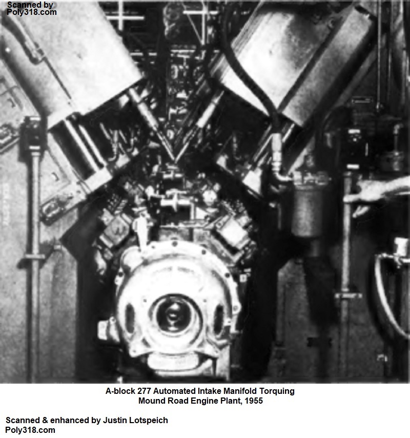
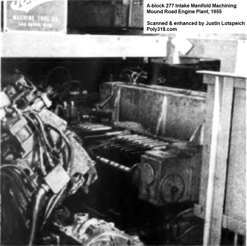
From the Cincinnati broacher, intakes went through a Buhr multi-station transfer machine uniquely designed for the A-block Qualimatic engine plant (Figure 14a). Traditionally, the drilling head for the intake manifold mounting holes was positioned vertically under the intake manifold, which caused falling chips to quickly plug up the tooling and required frequent maintenance. Some engine plants chose to use an over-head vertical drill and flip the intake manifold upside down, but this process required unclamping the intake to flip and re-clamp it, which resulted in alignment inconsistencies. To resolve the issues, the design team working with Buhr invented a new machine that slid the manifolds on rails indexed by a transfer bar on lugs cast into the manifold; now you know what those rectangular nubs are on the manifolds. The two stations clamped the manifold in place and rotated it up 45° to position it for machining. Horizontal drills came in from the side to process the holes while milling cutters simultaneously machined the front and rear ends of the manifold. The manifold slid into another station that rotated it in the opposite direction without unclamping it, and the other side was processed in the same fashion. In another station of the same machine, all the coolant ports were drilled and tapped along with the carburetor and accessories holes. The Buhr machine handled two-barrel, four-barrel, and dual-quad manifolds automatically sensing the manifold from the location of the indexing lugs and automatically adjusting the tooling via pre-programmed sets of heads.
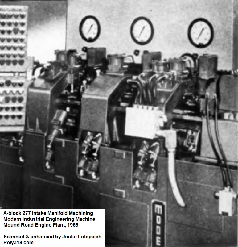
After machining, the intake manifolds automatically passed through a Centri-Spray washer and then into a Modern Engineering Equipment pressure testing machine (Figures 14b). The testing consisted of three stages: one stage tested the coolant jackets, another the upper intake runners, and the last the lower intake runners. There was no test for the exhaust crossover from what I can find in the design team’s and equipment’s literature, but I assume the crossover would have been tested too. If a manifold failed the pressure test, the machine automatically sprayed the manifold with one of three colors to indicate which circuit was faulty and automatically ejected the manifold from the conveyor line onto a “defect” conveyor for further inspection. If more than five manifolds in a row failed the test, the machine automatically shut down and alerted the operator for inspection. The defective manifolds were inspected by the operator in a water testing machine that filled the runners and jackets with pressurized water. Manifolds that passed the test were placed back on the line, while manifolds beyond repair were sent to the scrap rail cars for recycling.
Exhaust Manifold Production
The exhaust manifolds were some of the most difficult parts to process in the entire plant due to their flexibility, ease of damage, and awkward shape. While we often think of any cast-iron as extremely stout, the Production Design team used the analogy in an industry essay that under heavy machining processes like broaching and milling, cast-iron acts more like rubber. Due to the shape of the manifolds, traditional dial-indexing machines could not be used to complete the many processing functions. Instead, the design team working with equipment manufacturers designed a series of machines.
The castings were inserted by hand into a Blanchard three-wheel, vertical-spindle, automatic surface grinder that removed 1/8” of material from the head mounting flange for a finish within 0.002” tolerance of flat. The manifolds were moved by hand into a Snyder transfer machine that first drilled the mounting holes. It automatically turned over the manifold and bored and faced the head-pipe flange. It then drilled the heat-riser valve shaft holes (if applicable) and drilled, reamed, and tapped the head-pipe mounting holes. For manifolds with a heat riser, two bushings dropped from a hopper and were pressed into the shaft holes (the valve and shaft assembly would be added later). At the end of this machine, the manifolds were washed and pressure tested for leaks. Manifolds that failed the leak test were automatically taken off the line for inspection via water testing like the intake manifold, while those that passed moved down the conveyor either to the engine assembly line or to have the heat-riser valve assembly installed.
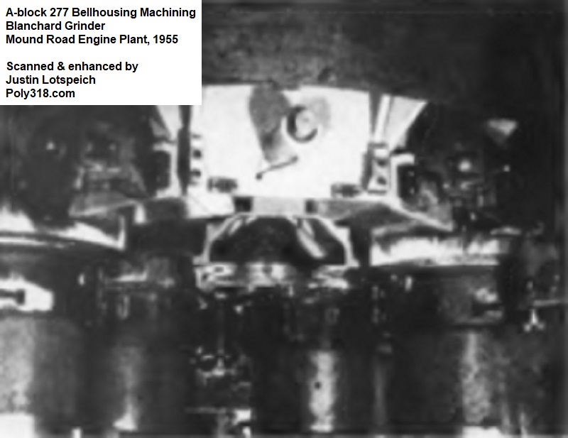
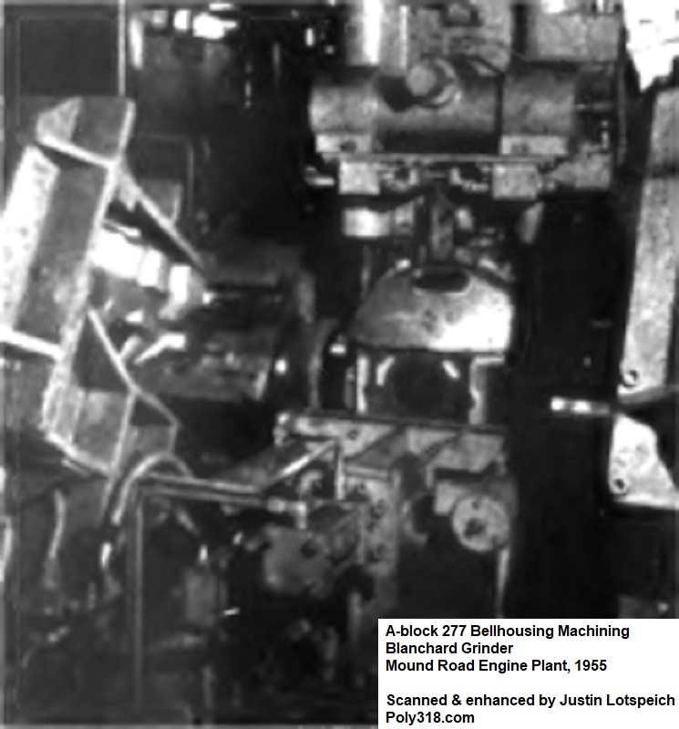
Bellhousing Production
The Qualimatic plant produced the transmission bellhousings keeping in mind that the PowerFlite and TorqueFlite A466 transmissions used a separate bellhousing similar to a standard transmission. The design team chose to use grinders to machine the bellhousing since the forces applied during broaching and milling would distort and damage the bellhousing.
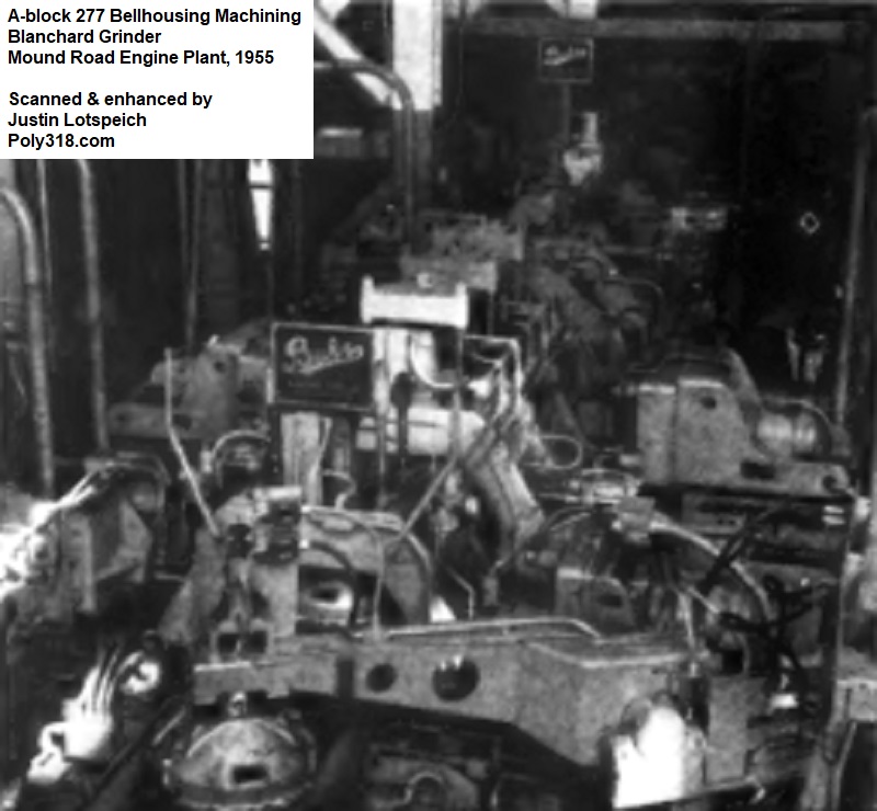
The rough bellhousing castings were automatically fed into a Blanchard four-wheel, vertical spindle, automatic surface grinders that processed the surfaces through stages of rough-grinding, semi-finish grinding, and finish-grinding (Figures 15a – 15c). About 1/8” of material was removed from each surface, and surfaces were held to within 0.002” flatness.
The bellhousings passed into a Buhr multi-station three-stage transfer machine that exemplifies the advancement in production that the design team and equipment manufacturers built into the Qualimatic plant and design of the A-block engine. Prior to the Qualimatic plant, bellhousings required multiple machines to process, and the repeated clamping and unclamping for each bellhousing introduced tolerance inconsistencies that could have significant implications on the pilot-bearing, input-shaft bearing, and other wear. To improve the process, a novel Buhr machine was designed. The first stage of the machine ground the engine plate mating face and transmission mating face. The second stage ground the pan-rail face. The third stage processed the linkage mounts. The machine then completed the milling, drilling, reaming, countersinking, boring, and tapping of the mounting holes, two dowel alignment holes, front input-shaft hole, and the starter-shaft hole. All the machining was performed with the bellhousing secured only once so that the many different modifications were performed in alignment. The bellhousing was automatically gauged prior to leaving the machine.
An automatic swing-arm grabbed the bellhousing, rotated it, and placed it into an Apex assembly machine where two Welch plugs were fed via hopper and pressed into the bellhousing. The bellhousing was then sent through a washer before joining the engine assembly line.
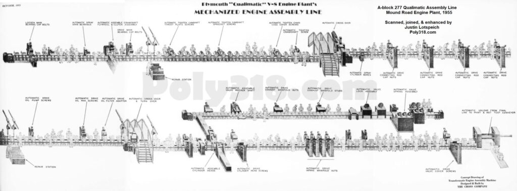
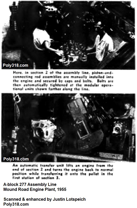
Engine Assembly
The final engine assembly line was a massive 656’ long Cross Transfermatic machine built in three sections and two 120’ long cylinder head assembly machines (Figures 16a – 16e). The machines were synchronized at 16-second dwell time and 8-second index time to facilitate the consistent production of 150 engines per hour. At the end of the assembly line, engines left the pallets they had ridden on throughout the engine assembly process, and the empty pallets were automatically transferred back to the front of the line via a track in the machines’ bases. From there, the engines proceeded to the electrostatic paint line. Unfortunately, I have not been able to locate any factory documentation going into great detail about the assembly process or anything about the painting process.

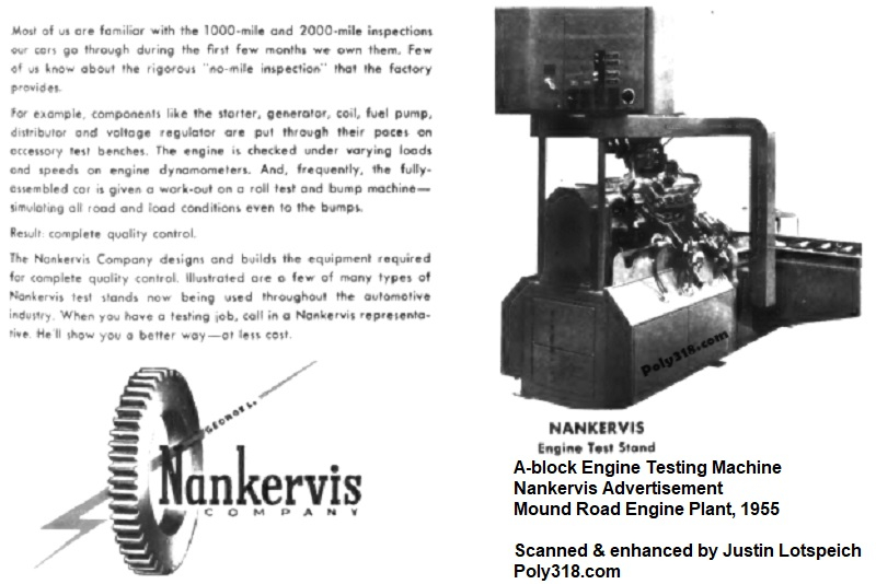
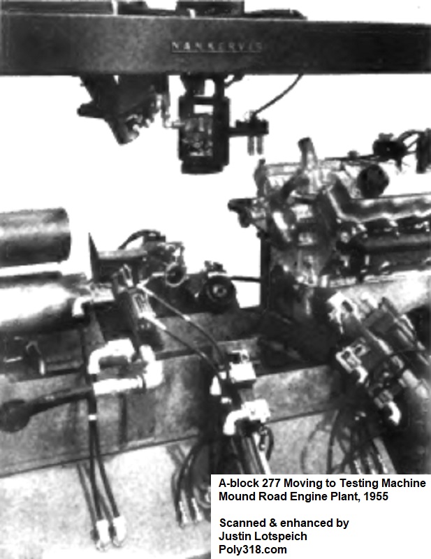
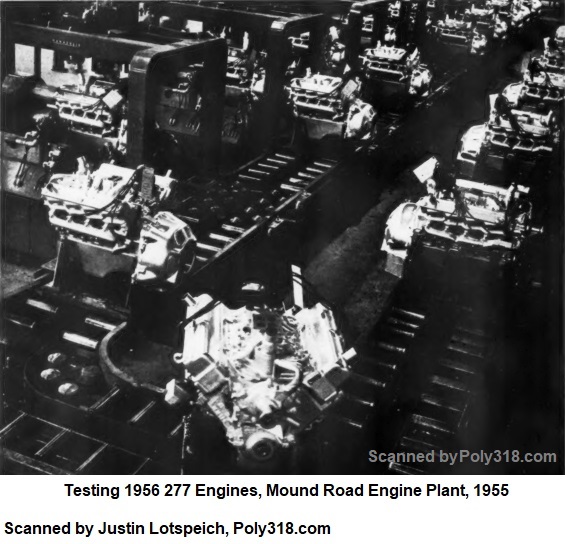
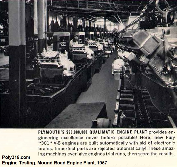
Engine Hot Testing
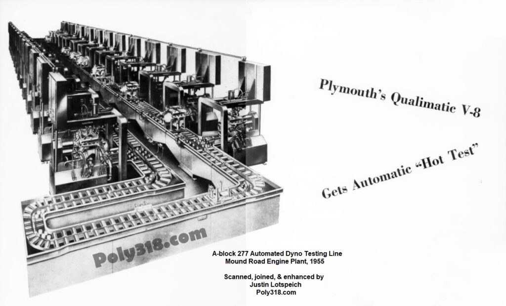
Revolutionary to mass engine manufacturing, the A-block was the first engine to ever be tested at the plant long before it was installed in a vehicle. The testing machines with the help of the design team were produced by the George L. Nankervis Company and were the first of their kind (Figure 17a). The design team’s first draft of the testing system was to pull a batch of engines off the line, test them, and return them to the line, but this process would require a 20-minute stop-and-go cadence in the engine assembly line that destroyed the chance of reaching the goal of 150 engines produced per hour.
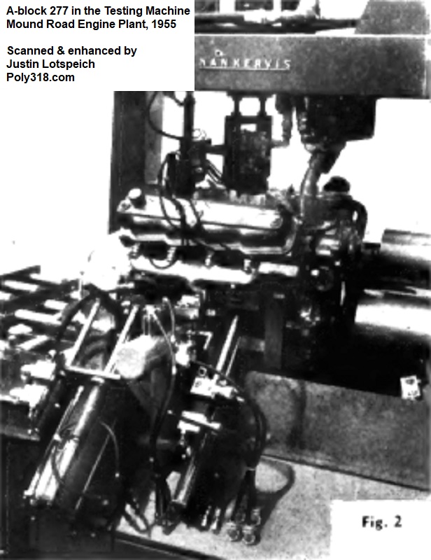
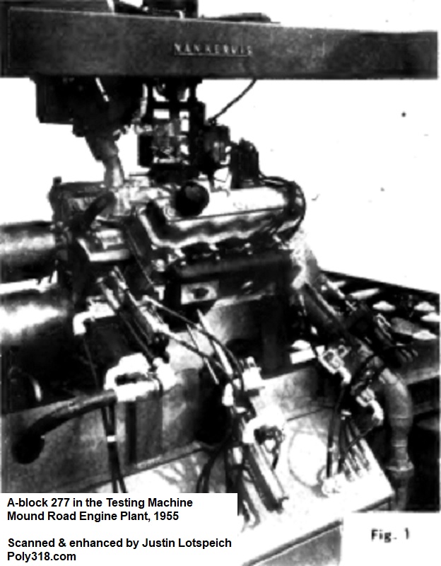
After many subsequent drafts, the team ended up with a system that would test every engine on the assembly line at a consistent pace. Painted engines were brought into the testing line via overhead conveyors, lowered onto a test pallet, and sent down the conveyor. One empty pallet was placed in between the untested engines to serve as the pallet for conveying the tested engines off the line. There were three batteries of testing stands containing 24 stands per battery for a total of 72 test stands. The system was automated where a free stand would recognize an untested engine and vice versa to where no stand was empty long and all engines were tested. The test stands would not recognize the already tested engines that would pass down and off the line. All of this automation is now common place with our barcode and QR code systems, but in the A-block Qualimatic plant it was based of a series of indexing mechanisms that worked in conjunction with camshafts on the engine pallets, chain-driven pin dollies, and camshaft followers on the test stand transfer machines to detect untested engines in need of a testing stand.
At each test stand, different equipment was automatically hooked up to substitute for the missing components (carburetor, distributor, fuel pump, etc.) using over 900 air-powered cylinders (Figure 17b – 17d). Hot coolant lines, hot oil lines, a natural-gas carburetor, ignition system, exhaust system, water-pump driver, and pneumatic crankshaft starter were attached. Sensors confirmed that all the equipment was functioning properly before actuating the crankshaft starter.
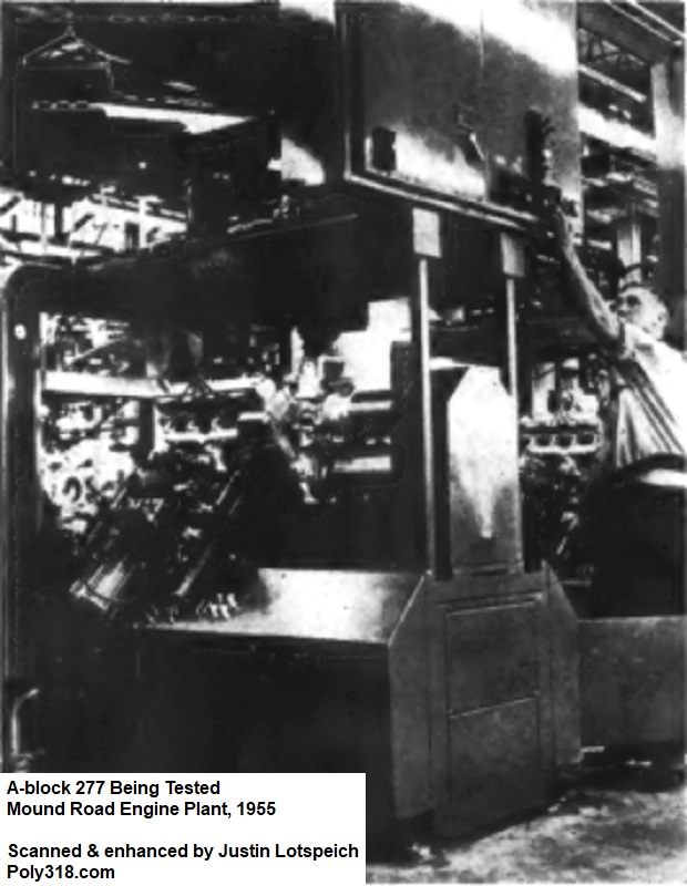
The engines were tested for twenty minutes with sensors measuring and reporting data to the operators. The test started at low 400 – 450 cranking RPM to prime the systems before the engine was fired. The engine ran for seventeen minutes for camshaft and lifter break-in before shutting off. At this point, the external oil circulation lines were closed with oil in the pan, and the engine fired again and continued running to test its oiling system. At this point, a testing technician took control inspecting the gauges and listening to the engine (Figure 17e). The technician brought the engine to wide-open throttle listening for any issues, particularly with lifter noise. He wrote down his findings on a tag affixed to the engine and then manually pressed either an “accept” or “reject” button. The design team purposefully made this last inspection manual to ensure quality control since they could have easily programed an automatic “accept” or “reject” into the system based off the sensor data but wanted human input as well. After the inspector pushed the button, the engine ran for two more minutes before the machine automatically stopped, drained the fluids, and disconnected the equipment.
Accepted engines were automatically transferred onto an empty pallet on the conveyor system and sent to the Shipping Department (Figures 17f – 17g), whereas rejected engines, which were extremely rare, were automatically pulled off the line for examination and repair if necessary.
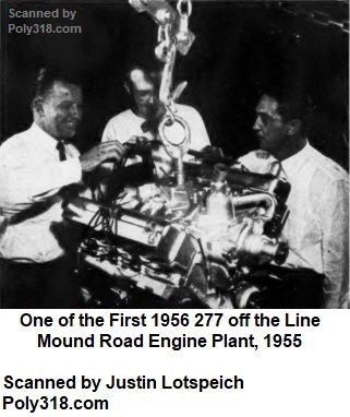
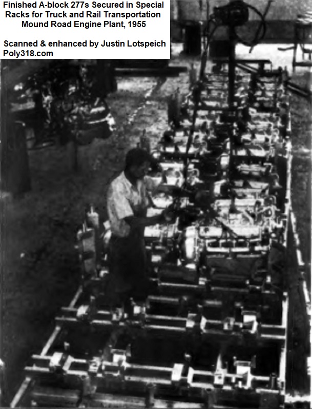
Shipping Department
The first A-block 277s at the Qualimatic Mound Road Engine Plant began rolling off the line in July 1955 during the pilot destined for 1956 model Plymouth Plaza, Savoy, Belvedere, and Suburban (Figure 18a). By August 15, 50 engines per hour were rolling off the line, and by October 15 the plant was at full production of 150 engines per hour. The Windsor, Ontario plant learned the hard-fought lessons of the Qualimatic Mound Road Engine Plant team, and the A-block 303 began rolling off the line in the summer of 1955 destined for export vehicles and domestic Plymouth Fury models. The Mound Road and Windsor engine plants would produce all the A-blocks from 1956 – 1967 that we admire.
At the end of the production line, engines that passed hot testing were loaded onto specially designed stackable shipping racks, six engines to a rack (Figure 18b). These racks had hangers that secured the engines from moving and rubbing against each other. The loaded racks weighing 4,600 lbs. each were loaded via a custom 10,000 lb. lift truck into specially fitted rail cars or truck trailers. The rail cars held 21 racks for 126 engines per car and delivered their precious poly cargo to either the Los Angeles or Evansville, California vehicle assembly plants starting in August 1955. The truck trailers held 8 racks for 48 engines and went to local vehicle assembly plants. In comparison to the old method of loading engines one at a time into a truck trailer that took three hours, the Qualimatic rack design loaded the trailer in less than five minutes.
Missing Details
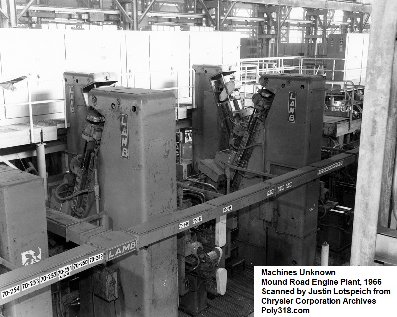
Unfortunately, the hundreds of pages of articles, essays, and photo captions I have researched and examined leave out some aspects of A-block engine production including lifters, pushrods, timing sets, oil-pump pickups, pulleys, valve covers, oil pans, timing covers, fasteners, etc. With the information I did find and include in this research article, I can make educated assumptions about many of these components by comparing their likely machining methods needed to other known processes, but the proven processes may be lost to time unless somewhere in my future research I come across more documentation. Many of these components, such as oil pans and valve covers, were likely built at another factory and shipped to the Qualimatic plant. Figures 19a – 19b shows equipment I found in the Stellantis archive that were not specifically labeled or annotated but included in the Mound Road Engine Plant folders.
Conclusion
I hope you have enjoyed touring the Qualimatic Mound Road Engine Plant that built the poly A-block and learning about how the engine, production processes, production equipment, and plant came to be. It would have been a wonderful experience to visit the factory under full production to witness the meshing of state-of-the-art automation and human know-how, and I expect everyone who worked at the plant did so with great pride. I like to think I and those who visit this website carry on that pride in either keeping their A-blocks running or at the very least enjoying reading about them.
A poetic irony that doesn’t escape me is that the Mound Road Engine Plant’s first junior resident engineer hired in 1954 was a young and now legendary Willem Weertman, who had quickly worked his way up in Plymouth after joining their engineering staff in 1949 after finishing his residency education (Figure 20a). Weertman is never mentioned by the leaders of the different teams responsible for designing the A-block engine, production processes, equipment, and plant, and he appears in only two photographs I have been able to find. It is apparent he was not a key designer but likely supported the chief engineer and plant engineer during his training. Regardless of the extent of Weertman’s role, he was part of a team that helped usher in a new era of V8 engines with the A-block, and he would go on to lead the team that took the A-block’s platform and modified it into the LA273, starting another era of small-block V8s that would quickly put an end to the A-block. In essence, the person who helped give birth to the A-block would be its grim reaper less than a decade later. I take solace in the fact that the lessons Weertman learned from the A-block influenced his fundamental roles in helping design the LA, B, RB (including the 426 Max Wedge), and 426 Street Hemi. While many people have disregarded the A-block over the decades, its design and proven durability influenced some of the iconic Chrysler Corporation engines that followed. The Qualimatic Mound Road Engine Plant went on to influence every domestic and likely foreign engine plant in its automation and production processes. The Mound Road Engine Plant was shuttered by Daimler Chrysler in 2002 and demolished in 2003. The land is now a parking lot used to store new vehicles. The Windsor, Ontario plant is still in use by Stellantis as of 2024.
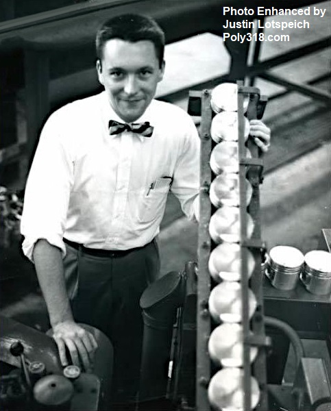
with A-block 277 Pistons, Mound Road Engine Plant, 1955
Acknowledgement
I’d like to thank my many professors back in my undergraduate and graduate education days who taught me the scientific method, how to approach scholarly research projects, and ways to hunt for obscure evidence. I thank the University of Colorado library system and City of Aurora public library system where I was able to access databases that led to the discovery of articles and essays, some of which were on microfiche. Finally, I thank the Historical Services Department at Stellantis (formerly Chrysler) for allowing me access to the very few surviving Mound Road Engine Plant and Windsor Engine plant photographs and documents for scanning and not-for-profit use here.