Poly 318 Ignition Timing, Points Adjustment, Distributor Conversion
(applicable to 277, 301, 303, 313, 318, 326, 390, 402 and LA 273, 318, 340 and 360 engines)
Introduction
Vacuum advance to ported or manifold vacuum for performance or stock? How to set timing? How to clean and set distributor points? How to convert to electronic ignition? I answer these question in this tech article. These questions and procedures can seem confusing and overwhelming due to the multiple variables and time required for tuning, so I wrote this article to discuss my recommendations and the methods I use. Timing is highly dependent on the specific engine build, the air-fuel mixture, distributor specs, compression ratio, elevation, and other variables. Service manual recommendations are baselines for economy commuting and are not necessarily the best adjustments for optimal performance. I break the timing procedure into the camps of “basic” and “optimal.” I recommend using the “optimal” method on all engines since it will give the best timing for the specific engine, but I provide both methods since some people may want to use a quicker “basic” method if optimal timing isn’t desired. Even if you are interested in the “optimal” method, read through the “basic” method first since I provide necessary details that apply to the “optimal” procedure.
What Is Mechanical and Vacuum Advance?
I want to preface the timing procedures with a summary of mechanical and vacuum advance. Mechanical advance is controlled by the engine RPM via centrifugal weights and springs internal to the distributor and increases with engine RPM, whereas vacuum advance is controlled by engine vacuum related to engine load and depends on if the vacuum signal comes from ported or manifold vacuum, which I discuss in great detail in the the next paragraphs. Since street and most street/strip cars probably spend over 85% of their life at low to part throttle and at sustained lower-RPM cruising speeds, vacuum advance is a huge benefit. Some will argue that relying on mechanical advance and locking out vacuum is better for street driving and performance, but in reality an engine primarily used on the street properly tuned with vacuum advance will outperform in both power and driveability compared to the same engine with only mechanical advance due to the physics applied to street car combustion dynamics under normal street loads/conditions. The idea of running only mechanical advance comes from racing where the engine doesn’t care about low-speed performance and behavior and only cares about heavy to wide-open throttle where vacuum advance is unnecessary.
Should Vacuum Advanced Use Ported or Manifold Vacuum?
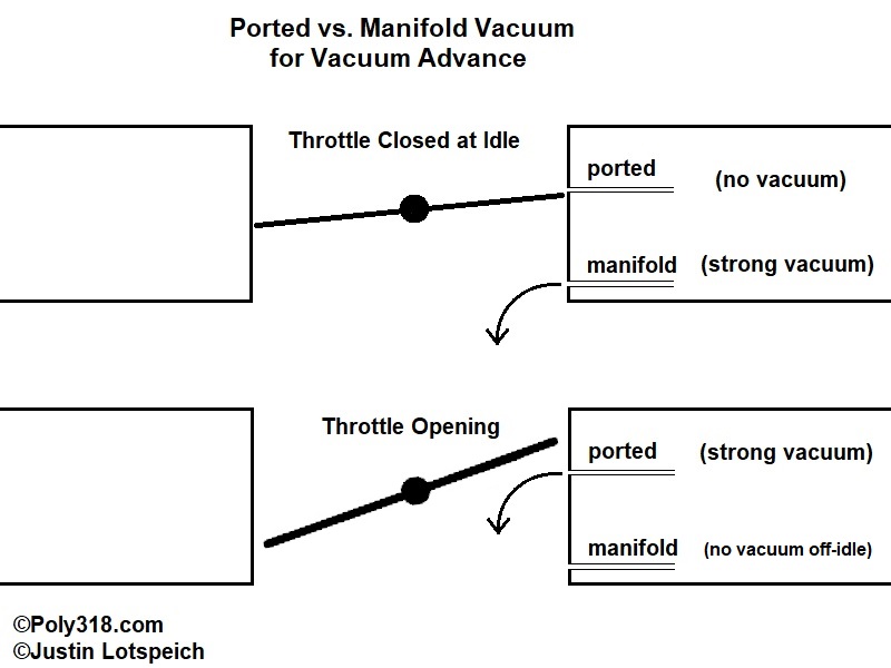
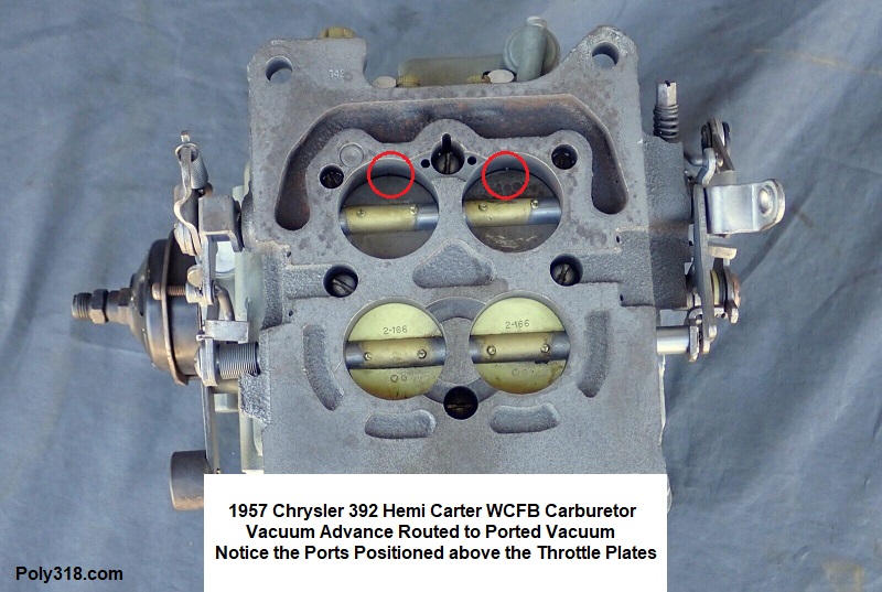
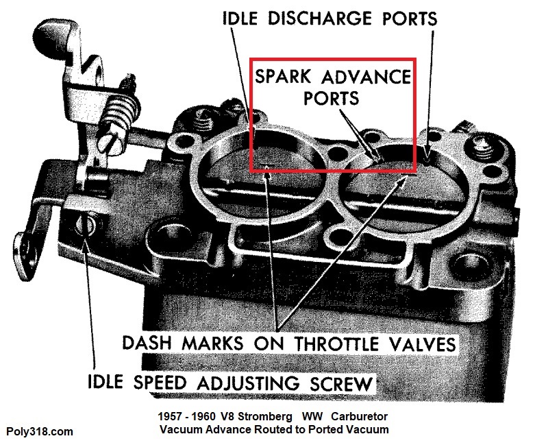
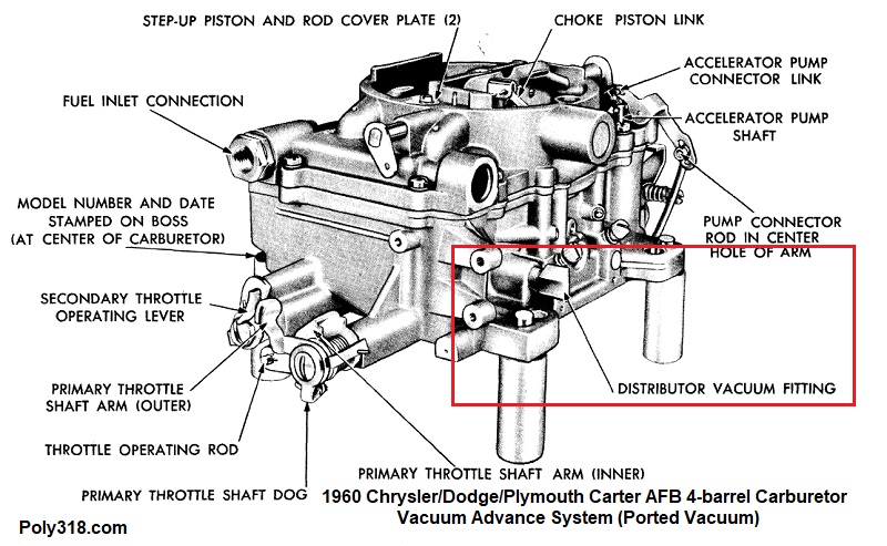
Some major disagreement I want to address is manifold versus ported vacuum for the vacuum-advance signal. The majority of street and street/strip engines will perform best with vacuum advance attached to ported vacuum on the carburetor, not manifold vacuum. Some people claim vacuum advance should always be attached to manifold vacuum regardless the engine build and that ported vacuum was used only because of emissions/smog laws/regulations. These claims misunderstand street engine physics and conditions and the history of vacuum advance in pre-emissions performance and commuter cars. Just looking at how the factory routed vacuum advance in the 1950s – 1960s is enough to torch holes in the “only manifold vacuum” defense. Looking at Figure 1a, ported vacuum is piped into the carburetor just above the throttle valves where the vacuum signal is usually 0 inHg with the throttle valves closed against the hot-idle screw/stop and immediately increases as the throttle plates open. (Note that engines with aggressively long -duration and overlap camshafts that require more idle speed to keep running in gear may have some ported vacuum signal at idle since the throttle plates are opened above the ported vacuum holes). Conversely, manifold vacuum is piped into the carburetor or intake plenum/runner below the throttle valves and sees highest vacuum with the valves closed at idle and drops to or very close to 0 inHg immediately when the valves open. The manifold vacuum won’t rise and stabilize again until RPM stabilizes or the valves close.
Looking at both forms of vacuum together, as soon as the throttle plates begin opening, manifold vacuum crashes while ported vacuum skyrockets. Most engines paired well with street and street/strip distributors, camshafts, and converters will perform best with no vacuum advance at idle and with more advance immediately as the throttle is opened and under load to assist combusting the mixture until mechanical advance comes in once RPM is high enough. Contrary to what some might say online, if vacuum advance is connected to manifold vacuum in these street engines, the vacuum advance will provide the most advance at idle and will crash to or close to 0° as soon as the throttle is opened. Let’s use two examples to demonstrate what happens: We have an engine that needs 12° BTDC advance at idle. The vacuum advance canister is set to provide 14° advance at peak vacuum. Let’s hook vacuum advance to manifold vacuum. With vacuum advance providing 14°, we must set initial timing at 2° after TDC to get an idle timing of 12° before TDC (14° BTDC – 2° ATDC = 12°BTDC). This car idles just fine at a stoplight with the throttle valves closed, but as soon as the throttle plates open and manifold vacuum crashes to 0 inHg, the 14° of vacuum advance goes away completely, and timing retards to a terribly insufficient 2° ATDC right when the engine needs more advance. The mechanical advance hasn’t kicked in yet because the engine RPM is too low to spin the weights outward, so the engine falls on its face. As we drive around town at lower RPM, we experience similar stumbles each time we open the throttle to speed up and manifold vacuum crashes.
Now let’s take this same engine and hook vacuum advance to ported vacuum like so many 1950’s and 1960’s performance and commuter cars/trucks, which I provide evidence for below. We set initial timing at 12° BTDC at idle with vacuum advance disconnected. We connect the vacuum advance to ported vacuum, and initial timing doesn’t move because there is no ported vacuum signal at idle. From idling at a stoplight, we accelerate, ported vacuum comes all-in, and vacuum advance immediately advances timing when combustion desires more advance but before mechanical has the ability to kick in. In our example, the 12° BTDC at idle may advance to say 20° BTDC, depending on the vacuum can and distributor’s adjustments. Once the throttle plates are opened to where ported vacuum begins to drop off, mechanical advance is already at work supplying the combustion process with the advance it needs to compensate for the retarding vacuum advance. As we cruise around town at lower RPM and open the throttle, ported vacuum increases again providing additional vacuum advance.
One alternative for getting around the advance crash that happens when plumbed to manifold vacuum, and believe it or not plenty of people online promote this scary method, is to set initial timing wherever the engine wants with vacuum advance disconnected, and then plug in the vacuum advance to manifold vacuum and call it good. For our example of an engine with 12° BTDC initial, this method means the engine is receiving an additional 14° of advance from vacuum advance on top of the 12° BTDC initial for a wild 26° BTDC advance idling at a stoplight or in a driveway/parking lot. Good luck starting that engine when hot, with detonation after shutting the throttle when descending a grade or coming to a quick stop, and with getting the engine to not diesel after shutting it off.
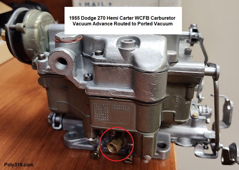
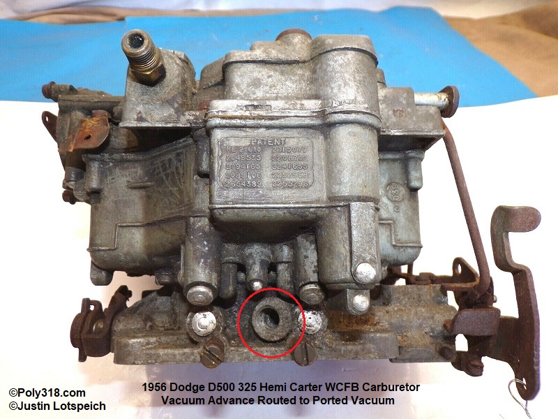
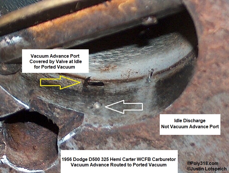
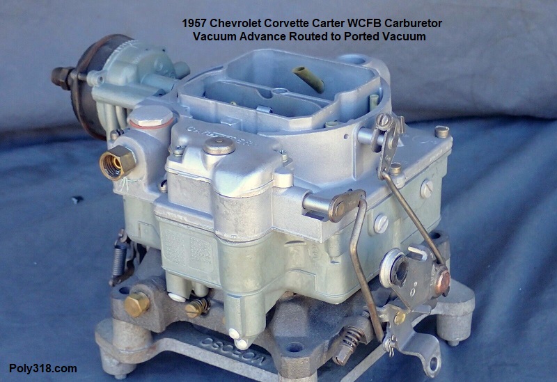
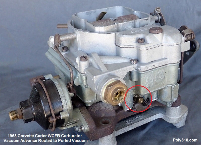
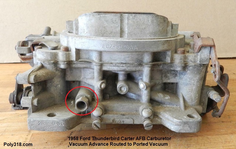
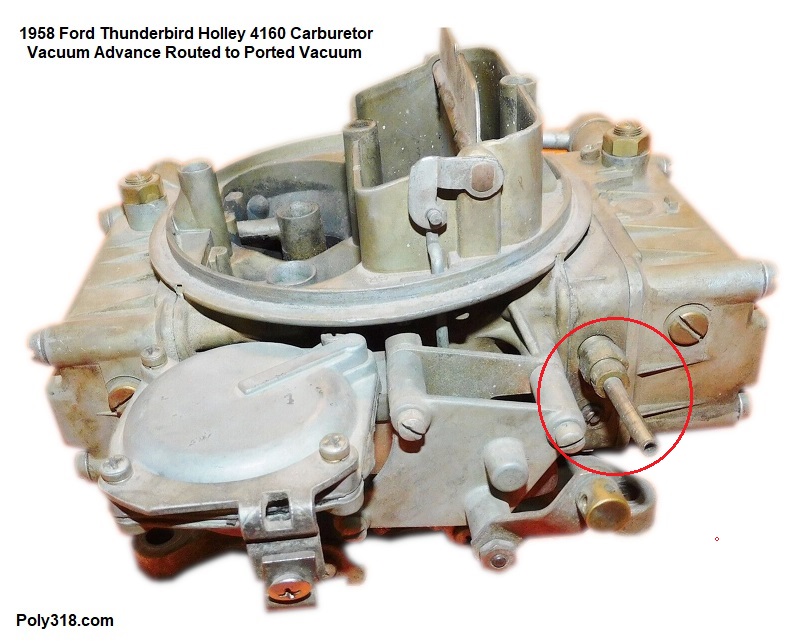
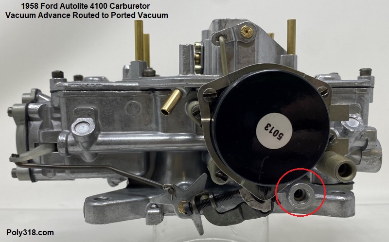
For those readers who after reading my examples still hang their hats on the idea that vacuum advance should be plumbed to manifold vacuum because they have claim Chrysler Corp., GM, and Ford used manifold vacuum on their performance and commuter engines before emissions laws forced them to change to ported vacuum, the following figures are going to be a great disappoint since they debunk this “ported is only for smog” claim. Starting at the oldest I’ve selected, although there are older examples, Figure 1b shows a 1955 Dodge “Super Red Ram” 270 Hemi WCFB carburetor with vacuum advance plumbed to ported vacuum. Note that the vacuum fitting is located higher up on the base plate with the ports coming out into the throttle bore as a slot at the throttle plate when closed. Figure 1c shows the iconic 1956 Dodge D500 325 Hemi’s WCFB carburetor with the vacuum advance plumbed to ported vacuum. I took a closeup in Figure 1d of where the vacuum advance port is located in the bore to show it is ported vacuum, which is a similar configuration for all of the below examples. Figure 1e shows the 1957 Chrysler 392 Hemi WCFB carburetor with vacuum advance plumbed to ported vacuum. If these photos don’t convince, how about Figure 1f, a 1957 Corvette WCFB carburetor equipped with a vacuum-advance distributor with, you guessed it, vacuum advance plumbed to ported vacuum. Then there’s Figure 1g, a 1963 Corvette WCFB carburetor with vacuum advance plumbed to ported vacuum. Not to leave out Ford, Figures 1g, 1i, and 1j show three different 1958 Ford carburetors (Carter AFB, Holley 4160, and Autolite 4100), all with vacuum advance plumbed to–ding, ding–ported vacuum. Some of the same models were used on 1957 – 1960 Thunderbirds and some on 390s in 1961. While the fitting on some of these examples is located high up in the base plate, I have confirmed visually by inspecting the base plates that the vacuum port(s) comes out at or just above the throttle plates for ported vacuum. So much for the argument that manufacturers used only manifold vacuum before emission laws since many of the most powerful engines of the 1950s from each of the domestic manufacturers used ported vacuum unless the distributor did not have vacuum advance.
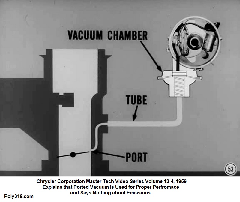
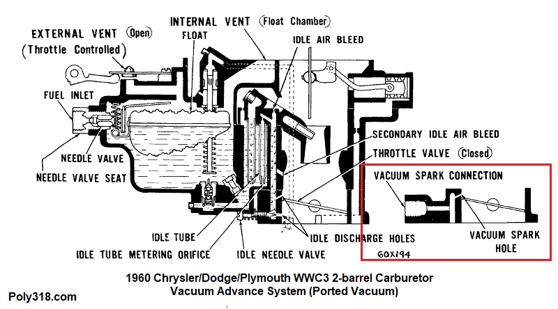
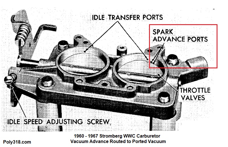
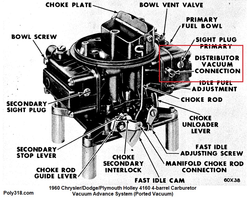
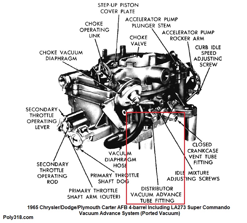
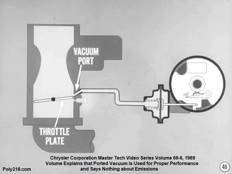
Factory publications also support the above evidence of 1950’s and 1960’s performance and commuter engines using ported vacuum. Figure 1k shows a factory service manual for the 1955 – 1959 Carter BBD carburetor with ported vacuum advance. Figure 1l shows a factory service manual for 1957 – 1960 Stromberg WW carburetors with ported vacuum advance. Figure 1m is a screenshot I took of a 1959 Chrysler Corporation Master Tech video that discusses using ported vacuum on the brand new distributor design for the A-block 318 and 326 and B/RB including the 1959 Plymouth HP 361 “Golden Commando” and the 413. Figures 1n – 1o show factory service manuals for 1960 – 1967 Stromberg WWC carburetors with ported vacuum advance. Figures 1p and 1q show 1960 – 1967 factory service manuals for Carter AFB and Holley 4160 carburetors with ported vacuum advance. Figure 1r shows a 1965 factory service manual with the iconic high-performance LA273 “Super Commando”‘s Carter AFB carburetor with ported vacuum advance. Figure 1s is a screenshot from a 1969 Master Tech video series explaining that ported vacuum for vacuum advance produces the best performance and says nothing about decreasing emissions.
My point in the last few paragraphs isn’t to argue that no engine before or after emissions laws ever used manifold vacuum from the factory or that some engines people are running today won’t see a benefit using manifold vacuum. Some factory 1950’s and 1960’s engines did use manifold vacuum paired with properly designed mechanical advance curves, and other engines didn’t even use vacuum advance and relied on a purpose-built mechanical advance distributor. Some engines people run today may benefit from manifold vacuum after careful tuning using ported and then manifold vacuum to determine which works best. My point is that a basis for arguing that manifold vacuum is the “correct” signal source because it was the standard for pre-emissions performance and commuter engines is illogical when looking at carburetors and factory service manuals for performance and commuter applications from the mid-1950s through the 1960s. There wasn’t a single year or couple of years that we can point to like the national side marker regulation in 1968 and say, “See, before 1968 the majority of vacuum advance was plumbed to manifold, and in 1968 everything changed to ported.” That’s because the emissions claim is a straw-man fallacy trying to drum up emotions over emissions regulation to try and convince readers rather through emotion rather than using proof from actual historical facts and engine dynamics.
Chrysler Corp. was at the forefront of performance engines in the 1950s and 1960s, and the 1956 Plymouth Fury with the new A-block 303 broke two NASCAR Speedweek speed records at Daytona for the standing mile and flying mile. That dual four-barrel WCFB, hot cam, dual points distributor engine from the factory plumbs vacuum advance to ported vacuum. Then came the 350, 361, and 413 pushing performance farther. At the same time, Chevrolet was pushing performance in the 283, 327, and 409 cars. Ford applied performance with the 430 in multiple divisions including the Thunderbird. After all the millions of dollars and tens of thousands of man hours all three manufacturers put into designing, testing, and refining their engines on the drafting table, prototypes, dyno, street, and race track, not to mention the same attention Carter, Stromberg, Holley, Rochester, and Autolite put into their carburetors, they chose to plumb vacuum advance to ported vacuum on many, many applications long before emission laws regardomg induction. The manufacturers clearly found that ported vacuum on many applications was superior to manifold vacuum for street cars. If we blindly believe those who argue for manifold vacuum based on historical precedence, I guess the engineers at Chrysler, GM, Ford, Carter, Stromberg, Holley, and Autolite really screwed up after all those millions of dollars and design, testing, and refinement.
If after considering my arguments that use evidence from engine dynamics, pre-emissions factory carburetor examples, and pre- and post-emissions factory publications readers are still skeptical about routing vacuum advance to ported vacuum, I highly recommend they run a long vacuum hose and gauge into the cabin, sketch out some tables on paper with RPM and vacuum that a passenger can record on, and see for themselves how manifold vacuum and ported vacuum behave in relationship to RPM and different load situations under normal driving conditions. Then get under the hood with a hand vacuum pump connected to the vacuum advance and start applying the different inches of vacuum recorded from the road tests while checking engine timing to see exactly how much advance, or lack thereof, is coming in from vacuum advance at the multiple RPM from the road-test charts. For most engines, I think they will find that vacuum advance plumbed to ported vacuum will provide the best performance and engine behavior on the street and street/strip. Outliers with particularly challenging engine dynamics might find that manifold vacuum provides a benefit. Until careful testing and tuning occurs, one will never know which vacuum source is best for that specific vehicle; what we do know is that the choice between the two has nothing to do with emissions and that the domestic manufacturers preferred ported over manifold in the 1950s and 1960s when considering the sum of their vehicles compared to the smaller percentage that used manifold vacuum or locked out vacuum advance completely.

Basic Timing Procedure (good for stock engine street cars):
This is the type of tuning found in factory service manuals, which doesn’t make it incorrect, but it doesn’t make it optimal. For the majority of stock and mildly hopped-up street engines, it will do the trick to keep the engine running well. Keep in mind that it will likely leave some power on the table that can be gained using the “optimal timing procedure” in the section below.
The following specifications are a good starting point for tuning a street and mild street/strip vehicle, and I go into further details to explain what these numbers and terms mean:
- Hot Idle Speed: 500 – 850 rpm as the cam requires in gear for an automatic and in neutral for a standard transmission.
- Note: set hot idle with the A/C compressor running.
- Adjustable Vacuum Advance Screw: Set midway in the adjustment range (usually 5 turns out)
- Initial Timing set at hot idle without vacuum advance attached: 10° BTDC
- Total Advance at 4,000 rpm without vacuum advance attached: 34° – 36° BTDC
- Total Advance at 4,000 rpm with vacuum advance attached: 44° – 56° BTDC
If I wanted to perform a basic ignition tune-up for a stock street engine with vacuum advance, this is how I proceed using an adjustable timing gun equipped with an integrated tachometer and dwell meter (if running points).
- Note: Performance mechanical-advance distributors—such as a Mallory YL dual-point mechanical—are a different beast and designed for wide-open-throttle racing, so follow the distributor instructions for adjusting the total mechanical advance and the advance curve.
- With the engine off, remove the air cleaner.
- Loosen the distributor clamp just enough to rotate the distributor with some resistance so it will not vibrate around on its own.
- Unplug the vacuum line from the distributor and plug the hose. Tip: A golf-ball tee makes an excellent hose plug (I still use the one my father used in the 1960s).
- Insert the proper-sized Allen wrench into the vacuum canister inlet (usually a 7/64″ or 2.5mm for Mopar cans depending on the manufacturer). Turn the wrench all the way clockwise until you just feel firm resistance. Turn the wrench counterclockwise counting each full turn until you just feel resistance. Divide this number in half, and turn the wrench clockwise in this amount. There will usually be about 10 full turns in a typical Mopar advance canister, so I would set the adjustment at 5 full turns out.
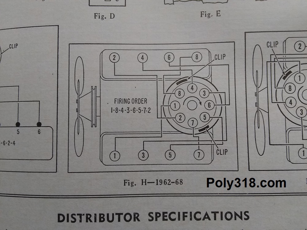
- Setup the timing gun with 12V power, a confirmed ground, the spark lead connected to cylinder 1 (Figure 2a), and the dwell lead hooked to the coil negative (if running points). Ensure the wires/pickup are clear of exhaust, fan blades, and belts.
- Start the engine and bring it up to running temperature ensuring visually the carburetor choke plate is fully open. Resting a hand atop the radiator at the intake port will tell when the thermostat opens when hot coolant rushes in.
- Set proper idle speed to 500 – 850 depending on the cam’s lope by adjusting the screw on the carburetor with the transmission in gear (automatic) or neutral (standard).
- Set the carburetor’s idle air-fuel mixture (see my carburetor tuning article for this adjustment).
- For points, check the dwell and adjust as necessary (see the section on points adjustment below).
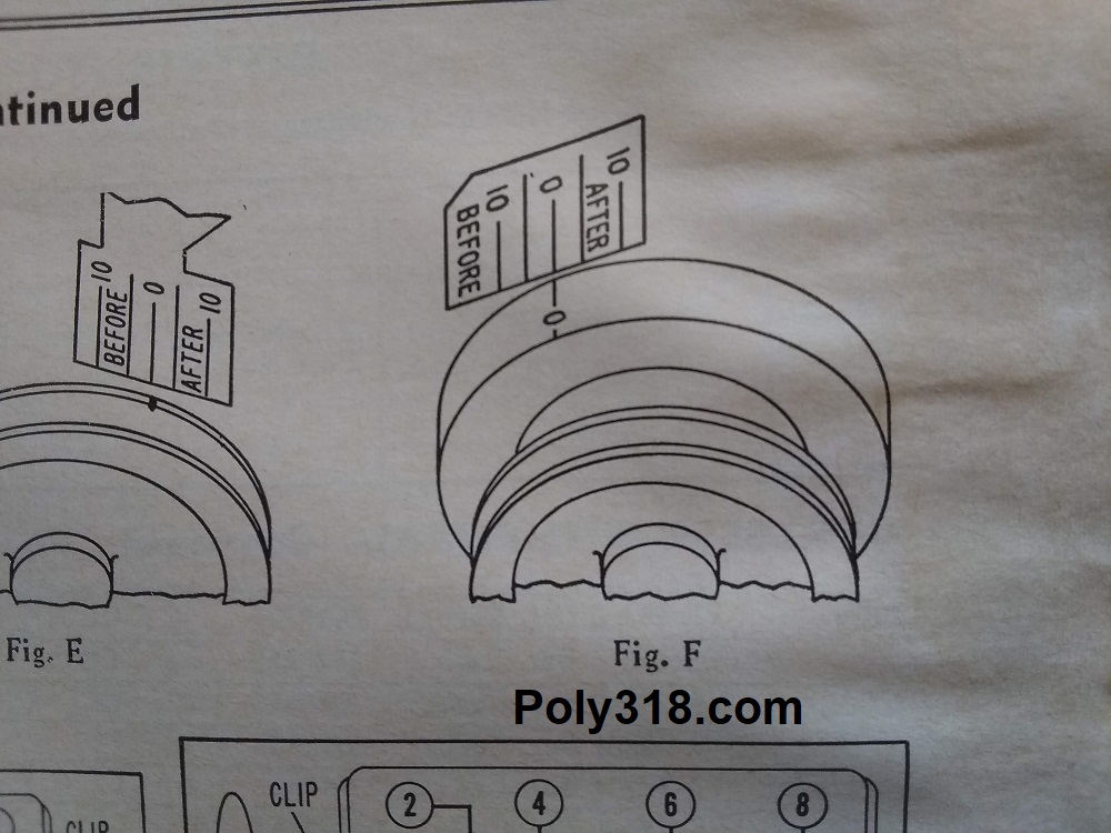
- With air-fuel mixture, hot idle speed, and dwell adjusted, set the timing gun to 10° BTDC and strobe the timing mark (Figure 2b). Slowly retard or advance the timing by rotating the distributor holding the distributor body until the harmonic damper and pointer timing marks align on 0°, which means the timing is set at 10° BTDC. The distributor should rotate with little force necessary but with some drag. Tighten or loosen the clamp bolt as necessary.
- Raise the gun timing setting to 34° BTDC and switch the gun to tachometer (the vehicle’s tachometer or a portable tachometer can be used too, although using a timing gun with built-in tach is easiest). Smoothly open the throttle by hand until the engine reaches 3,500 rpm. Do not simply flick the throttle but smoothly increase the rpm. Hold the rpm at 3,500 and switch the gun to the strobing mode. Adjust the timing up or down on the gun until the damper and pointer timing marks align. Advance the engine rpm up to 4,000 to see if the mark moves at all. If it moves, keep increasing engine RPM until the mark stops moving. Holding at this new rpm, adjust the gun timing until the timing marks align on 0°. Note the gun timing number and bring the engine back to idle. The measurement I just took includes the initial timing of 10° plus the distributor’s total mechanical advance or what I’ll call “total advance with mechanical.” Most V8 engines with iron heads will run best if this number is between 34° and 36°.
- Adjust initial timing to where total mechanical advance will be 34°, reset the hot idle speed, and recheck the total advance with mechanical following the steps above to confirm 34°. For our example, let’s say my timing gun read 32° when I first checked total advance with mechanical. I would raise my initial timing from 10° to 12° to bring my total advance with mechanical to 34°.
- Once total advance with mechanical is confirmed at 34° – 36° BTDC and hot idle is set, plug the vacuum hose into the vacuum advance can on the distributor.
- Note on vacuum ports: See the above preface for more details, but, in summary, for most street and street/strip engines ensure that the vacuum line is attached to ported vacuum on the carburetor and not manifold vacuum. For very high-performance engines with long-duration camshafts, vacuum advance might need to be connected to manifold vacuum to improve ideal characteristics, but the engine will suffer in performance at part throttle streetability.
- Repeat the steps I used to check total advance with mechanical, only this time set the timing gun at 44° as a baseline before revving up the engine. Increase engine rpm until the timing mark stops moving, increase or decrease the timing on the gun until the damper and timing tab marks are aligned on 0°, and note the timing number on the gun. This number is “total all-in with advance” and, ideally, will fall between 44° and 56° on an iron-head V8. If you subtract total advance with mechanical from this number, you get the amount of advance coming from vacuum advance. For our example, if total all-in advance with vacuum is 44° and total advance with mechanical is 34°, the vacuum advance is giving me 10° (44 – 34 = 10). If the total advance with vacuum falls within the 44° – 56° range, I am ready to take a test drive and see how the engine reacts. If it falls below 44°, I either need to raise the initial timing or physically modify the slots in the mechanical and/or vacuum advance mechanisms to increase the limits. In our example, since my initial timing is set at 12° to get a total advance with mechanical of 34°, I could raise initial advance by 2° to get 46° total advance with vacuum, which still falls within my desired 34° – 36°. If my total advance with vacuum is higher than 56°, the engine risks detonation at higher rpms while under load, especially on a hot day, when hauling cargo, and/or with lower octane fuel. I can either retard the initial timing or modify the mechanical and/or vacuum mechanisms to lock out advance. Note that the incorporated adjustment in the vacuum advance canister does not physically lock out vacuum advance but only adjusts the inches of vacuum required to activate the vacuum advance (see the “optimal timing procedure” below for details about adjusting the vacuum canister). Keep in mind that initial advance above 16° BTDC is near the upward limit for most iron-head V8s, and anything below 6° likely won’t provide quality power.
- Once my total advance with mechanical and my total all-in with vacuum are set, I quickly rev up the engine by hand using a smooth but relatively quick motion to about 4,000 rpm setting it naturally fall back to idle. I am looking to hear how the engine responds without load. If it backfires, bogs down, or acts otherwise problematically, I know I need to diagnose the issue since the engine will not run well on a test drive under load.
- If I am comfortable with how the engine responds to throttle without load, I use a fine-tip marker to mark a line across the distributor base and the block or intake manifold to note my initial timing location for ease of resetting timing.
- Snug down (do not overtighten) the distributor clamp to where the distributor will not turn with reasonable one-handed force, and confirm the marker lines align. Warning: Don’t turn the distributor by the vacuum pod but instead by holding the housing. Replace the air cleaner.
- I then take the vehicle out to test drive in normal around-town driving with traffic and stoplights/signs paying attention to low-rpm and mid-rpm throttle response and any signs of bogging down or detonation. I take my tools with me for ease of tuning. If I hear or feel detonation at low rpms, either initial timing is too advanced, or the vacuum advance curve is coming in too early. For vacuum cans with adjustment, I use an Allen key through the vacuum port to either slow down or speed up the curve (counterclockwise delays vacuum, clockwise advances it). If throttle response lags or the engine stumbles, initial timing might be too retarded, vacuum might be coming in too late, or I might need to adjust the accelerator pump.
- Once things are working well around town at low- and mid-rpm, I find my preferred boondocks road or freeway on-ramp where I can test with wide-open throttle passes from a rolling start and during hard kick-down shifting, again paying attention to throttle response, how the engine revs up, and sounds of detonation. If the throttle response is slow or the engine stumbles above 2,000 rpm, I might need more vacuum advance or to adjust the vacuum pod to adjust the vacuum curve to come in earlier. Fuel and spark quality may also be culprits to consider if I have difficulty resolving the issue with timing. If I hear/feel detonation, I have too much all-in advance and need to either lock out mechanical vacuum by modifying the mechanism’s slot or bring in the vacuum later by adjusting the vacuum curve with the Allen wrench.
The key to dialing in timing is patience, experimenting by making single and small changes at a time, and recording everything I change. Using marker lines on the distributor/intake as I make adjustments to initial timing lets me track changes and quickly move back to earlier settings on the fly without using the timing gun while on test drives. If I am having issues diagnosing a problem, unplugging the vacuum advance, plugging the vacuum hose, and driving without vacuum advance is a basic step in troubleshooting to remove that variable. A healthy engine should run just fine with no vacuum advance and 34° – 36° total with mechanical for the purpose of diagnostics. It will not be optimal for combustion and street driving long term, but it will tell me if the vacuum advance is the issue if the problems go away.
Optimal Timing Procedure (for stock and performance engines):
With performance comes a more complex method of timing, and even a stock engine will benefit from this method. These steps are not covered in factory service manuals because a typical customer having a consumer vehicle tuned up or even people intimate with performance vehicles won’t feel the difference between a loss or gain of, for example, 15 HP; a race track timing slip will, however. The first thing we need to do is “baseline” the distributor. Having a note-taker in this procedure really speeds up the following process, but it can be done solo. Before starting, take a sheet of paper and draw two separate charts each with two columns. Label the right column “rpm” and the left “degrees.” Label one chart “vacuum” and the other “mechanical”. Here’s an example:
Mechanical Vacuum
RPM | Degrees RPM | Degrees
Idle | Idle |
Moves | Moves |
1500 | 1500 |
- Unplug the vacuum hose from the advance canister. Insert the proper-sized Allen wrench into the vacuum canister inlet (usually a 7/64″ or 2.5mm for Mopar cans depending on the manufacturer). Turn the wrench all the way clockwise until you just feel firm resistance. Turn the wrench counterclockwise counting each full turn until you just feel resistance. Divide this number in half, and turn the wrench clockwise in this amount. There will usually be about 10 full turns in a typical Mopar advance canister, so I would set the adjustment at 5 full turns out.
- Plug the hose into the vacuum canister and ensure vacuum advance is plugged into ported vacuum. Hook up the timing gun as described above, and start the engine with the transmission in park (neutral for standard).
- With the engine at running temperature and idle, adjust the gun until the damper and pointer timing marks align on 0°. Record this initial number in the “vacuum” chart, for our example “idle” RPM and 10°.
- Slowly and steadily, increase the throttle by hand until the timing mark just begins to move. Adjust the timing light advance until the damper and pointer marks align on 0° and record this number and the rpm (what I have listed as “moves” in the example chart, so let’s say 1200 RPM | 12 Degrees. Continue this procedure in 500 rpm increments until the timing mark stops advancing, recording the numbers at every 500 rpm. The last recording will be total all-in advance with vacuum.
- With the engine back at idle, unplug the vacuum advance from the distributor and plug the hose. A wooden golf tee makes for a perfect plug (I still use the one my father used in the 1960s).
- Slowly and steadily increase the throttle by hand until the timing mark just begins to move. Adjust the timing light until the damper and pointer marks align on 0° and record this number and the rpm on the “mechanical” chart. Continue this procedure in 500 rpm increments the same as above until the timing mark stops advancing. This is total advance with mechanical. Subtract this number from the total all-in with vacuum and I have advance from vacuum. Subtract initial timing from the total advance with mechanical and I have my advance from mechanical. For example, initial is 10°, total all-in is 46°, and total with mechanical is 36°. Subtract 10 initial from 36, and I know mechanical is giving me 26°. Subtract 36 from 46 and I know vacuum is giving me 10°.
- Take graph paper with “rpm” on the Y axis in 500 increments and “degrees advance” on the X axis and plot all the timing numbers recorded at 500 rpm increments to form a graph. Mark the different rpms that advance comes in and advance stops. I now have the advance curve for this exact distributor with the vacuum pod adjusted at the halfway point.
Now that I have the distributor baselined, I can focus on timing. Good idle quality is key to performance engines, especially those with a lot of cam overlap.
- Disconnect vacuum advance and plug the hose.
- Set initial timing to 6°.
- Adjust hot idle speed to where the engine will idle well in gear for an automatic transmission and in neutral for a standard. Record this rpm in in both park and neutral.
- Adjust the idle air-fuel mixture (see my carburetor tuning article for this procedure).
- For automatics, place the car in gear and record the idle rpm and manifold vacuum.
- With the engine in park, increase initial advance 2° to make 8° and record the rpm and vacuum, which should both be higher than the baseline measurements.
- Reset idle speed and record the new vacuum reading both in park and in gear, which should be higher than the baseline.
- Continue this process until vacuum just begins to decrease.
- I shut off the engine and sit down to analyze all the data I have recorded. Out of all these recorded results, I choose the highest vacuum at the lowest initial timing when the engine was in gear. This initial advance will likely be between 8° and 16° depending on many variables including compression ratio. Err on the side of lower timing than eking out every last bit of vacuum. For example, if the best vacuum is 12 inHg at 14° advance, but going to 11° advance only decreases vacuum to 11.5 inHg, I go with the lower initial advance and sacrifice the vacuum. This will be the ideal initial timing for this specific engine, so all timing adjustments should take place in the mechanical and vacuum advance mechanisms thereafter.
- If I luck out, the distributor will give the perfect amount of mechanical to put total advance with mechanical between 34° and 36° and total all-in with vacuum at 44° – 56°.
- If mechanical advance puts too much in and puts advance over 36°, I have to remove the mechanical plate and weld on the stop to limit movement.
- To adjust vacuum advance limits, they make different vacuum canisters with different amounts of total advance they provide. Double the can number to give you total advance, so a #7 can will give 14° of total vacuum advance, which is the most common adjustable can. If adjusting the can clockwise to its limit (maximum advance) doesn’t provide enough advance, I need to use a can with more advance. If the can gives too much advance even when using a can with the lowest advance, I have to modify the can. To lock out vacuum advance, I use epoxy and a piece of rebar tie wire as a stop since welding like I do on the mechanical plate will melt the can’s rubber diaphragm.
- With timing adjusted, I am ready to test drive the car as described above.
- For even more precise tuning of the advance curve where the baseline chart for the distributor comes into play, I can either cough up the money to pay a dyno tuner, go to the drag strip, or mark off a 1/4 mile stretch of deserted road and have someone ride with me with a stopwatch. Ideally, the advance curve will be set by a dyno tuner (kill two birds with one dyno tuner by having the carburetor jetting tuned too), but I can get in the ballpark at the track. The general practice for performance street cars is to have the mechanical advance all-in by about 2,000 rpm, and I use different gauge weight springs to adjust that curve. In comparison, most stock mechanical advance does not come all-in until 4,000 rpm, which is way too high for performance builds. The rules to follow when tuning the mechanical curve are (1) speed up the advance curve as much as possible without causing running issues until reaching the best trap speed and (2) if denotation is an issue at full throttle, delay the advance curve.
Electronic Conversion
While points ignition can be perfectly reliable and last a very long time on our classic vehicles that are not driven daily like they used to be, LA-design electronic ignition is a superior design and easy and affordable to convert onto an A-block. If you plan on driving your vehicle more than 3,000 miles annually or if you are looking for the best performance, I recommend upgrading to electronic ignition; if you have a period-correct build with a stock distributor or Mallory dual-point or if you drive less than 3,000 miles per year, I detail points adjustment below.
Since the distributor is a crucial, delicate component of the ignition system, I recommend staying away from cheaply made imports, including Pertronix and Proform. Pertronix is all over the internet largely because they are inexpensive and have strong marketing strategies to the point one might confuse them for a high-quality brand. Do your own research online to see if their parts are actually made in the USA or China regardless of what they advertise since they have been proven to claim they are made in the USA but in fact use Chinese parts. For my personal experience, I have purchased two Pertronix distributors in the last ten years a few years apart for two different engines. With the first distributor, the timing mark jumped all over the place. I removed the distributor and setup a dial indicator on the distributor cam and found it was machined out of round creating the fluctuating timing. About five years passed where I thought maybe the company had improved, but the next distributor I purchased had a similar issue with the timing fluctuating, only I found the shaft was bent.
Some people also recommend the 2000 – 2013 Mopar Performance distributor, which uses miniaturized Accel GM HEI internals, but these units are known to have electronic issues including erratic timing that is the root cause for a host of issues. I stay away from them.
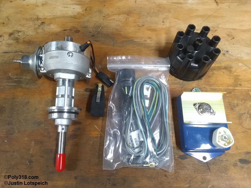
Many Mopar owners and racers, myself included, have had excellent results with Rick Ehrenberg’s trademarked HiRev 7500 distributor (P3690430), HiRev 7500 ignition control unit, coil, 0.5 ohms ballast resistor, and wiring harness (Figure 3). His kits can be seen on his website and purchased through him on ebay, user name rehrenberg. They are high-quality USA-made components with a reputation in performance circles who want the stock look since they look nearly identical to a factory electronic setup and are based off the 440 A-134 hi-performance units. If desired, the control unit can be hidden in the engine compartment to keep the factory points look. Ehrenberg sells the components direct, but some of them can be purchased through other vendors.
Important Adjustment Note: When adjusting the gap between the distributor cam and pickup, use a brass feeler gauge since a steel gauge will create drag and can also disrupt the magnetism.
Points Adjustment and Distributor Inspection/Cleaning
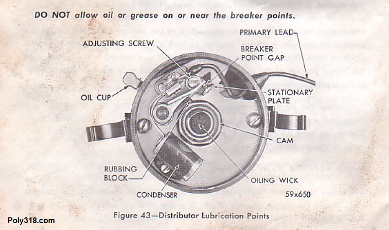
What do contact points even do? Essentially, they function as a type of trigger that helps direct coil current. The coil ground is connected to one side of the points. When the points are closed, the coil primary circuit is completed and lets the primary current flow for the coil to build up its charge; when the points open, the circuit is broken, primary current stops flowing through the coil, and the magnetic field in the coil collapses. Voltage builds high enough to move through the coil wire, transfer from the distributor cap to the rotor, jump from the rotor to the cap terminal, and flow down the spark plug wire where it eventually arcs at the spark plug. For this process to function properly, the points need to be clean and properly adjusted.
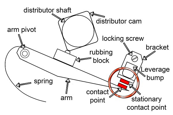
There are two adjustments for points: gap and its related dwell angle. Referring to Figures 4a – 4b, points gap refers to the gap between the two contact points when the rubbing block is up on the distributor cam lobe at full lift. Gap in measured while the engine is off. The dwell angle is measured with the engine running and measures how long points stay closed in degrees out of a 360° rotation of the distributor shaft. Dwell is the important measurement of these two, and gap simply puts the points in the ballpark so the engine will run in order to adjust dwell precisely.
Here is the process I use for inspecting and cleaning the distributor and setting gap and dwell:
- With the ignition switch off, unplug the coil-to-distributor wire and remove the distributor cap. Mark and unplug the distributor wires as necessary, making sure to mark the #1 plug on the cap for reassembly.
- Remove the rotor. Inspect the rotor tip for corrosion. If lightly corroded, use fine-grit sandpaper to lightly clean the tip. If heavily corroded/pitted/melted, replace.
- Inspect the cap terminals for corrosion. Clean or replace similar to the rotor.
- Inspect the points rubbing block for excessive wear or damage. Plan on replacing if excessively worn or damaged.
- Inspect the cam lobe for debris. Wipe off the cam if necessary and wipe on a very, very small dab of distributor cam lube. Excessive or incorrect lube can fling off onto the points and cause spark issues.
- Inspect the ground and condenser wires for damage. Address if necessary.
- Push and pull the distributor shaft side to side and up/down looking for excessive play. If there is excessive play, the bushings and/or shaft are worn and will need replacing.
- Using a small, clean flathead screwdriver, gently push the points arm away from the stationary point about 1/4″ to visually inspect the points. Do not bend the arm, use excessive force, or pry the arm beyond its pivot range. Use a flashlight to inspect both sides of the points for burning, corrosion, and pitting.
- If the points are corroded to where they require heavy filing, remove the points from the distributor since debris will fall into the distributor. Place a clean points file in a vice and sandwich the points around the file. Holding the points so they do not flex or contort, move them back and forth across the file until the points are clean and trued up. The maximum allowed amount of pitted surface area is 30% after filing. Any more pitting, the points need replacing. Blow off the points with compressed air and reinstall being careful not to strip the screw threads or round off the screw heads.
- Rotate the engine clockwise when facing the front of the engine using a ratchet on the crankshaft bolt until the points arm is at full lift on top of the cam lobe. Once close to full lift, gripping the mechanical advance mechanism at the top of the shaft and rotating it by hand will give enough slop to precisely open/close the points.
- Factory poly A-block and LA points gap is 0.017”. Take a 0.017” feeler gauge (I use a wire sparkplug gauge since it is easier to get into tight spots) and gently try to insert it between the points. The goal is to be able to insert the gauge with slight drag/resistance but not enough to push open the points farther.
- If the gap needs adjusting, locate the locking screw attached to the stationary point. Loosen the screw keeping some light tension on it. Locate the prying points on the baseplate and the point bracket, which are often a small nub or notch. Using a clean screwdriver, gently pry the point bracket away from the other point to increase gap or toward the other point to decrease gap. Never pry on the point itself.
- Once the gap is set, tighten the lock screw snugly and confirm one last time the gap is properly set. Don’t over-tighten the screw.
- Reinstall the rotor and wipe off any grease and fingerprints with lacquer thinner or brake clean, for grease can inhibit proper electricity transfer. Reinstall the cap and wires.
- Hook up a dwell meter to the coil (I use the dwell meter on my timing gun). If using a two-lead meter, the black goes to a confirmed ground and the red goes to the coil negative post. If using a timing gun equipped with a dwell meter, the gun black lead goes to a confirmed ground and the dwell lead goes to coil negative. Ensure the wires are clear of any exhaust, fans, pulleys, and belts.
- Start the engine and bring it up to running temperature, holding your hand on top of the radiator near the intake port to feel when the thermostat opens and hot coolant rushes into the radiator. Note the dwell meter reading. An 8-cylinder engine should have 26° – 28° dwell ideally. If necessary, shut off the ignition switch, follow the above procedure for removing distributor parts, and adjust the points. If you increase the points gap, the dwell angle goes down since the points remain closed for a shorter amount of shaft rotation; if I decrease the gap, the dwell angle goes up. For example, if dwell is 30°, I would increase the gap very slightly (as in by .002”) and recheck dwell. If the dwell is 24°, I would decrease the gap very slightly and recheck dwell. Yes, this process can take multiple adjustments, which is why Chevy invented points that could be adjusted with the engine running using a long hex T-wrench through a door in the distributor cap. Unfortunately, Mopar did not use a similar system.
- Once dwell is set between 26° – 28°, confirm that the points screws are tight and that the rotor, cap, and wires are properly installed.