Poly A-block Engine Specifications
I have compiled these Poly 277, 301, 303, 313, 318, and 326 specifications from multiple factory manuals, brochures, service bulletins and my personal measurements. See the service manual page for digital service manuals I provide for free download.
Poly A-block Factory Engine Specs
| Year | CID | Model | Bore | Stroke | Comp Ratio | BHP | Torque | Notes |
|---|---|---|---|---|---|---|---|---|
| 1956 | 277 | First A-block | 3.75″ | 3.125″ | 8:1 | 187 @ 4,400 RPM | 265 – 272 @ 2,400 RPM | |
| 1957 | 301 | Car, V800 | 3.91 | 3.125″ | 8.5:1 | 215 @ 4,400 RPM | 285 @ 2,800 RPM | 1×2 Carburetor. 277 crank and rods, 318 block |
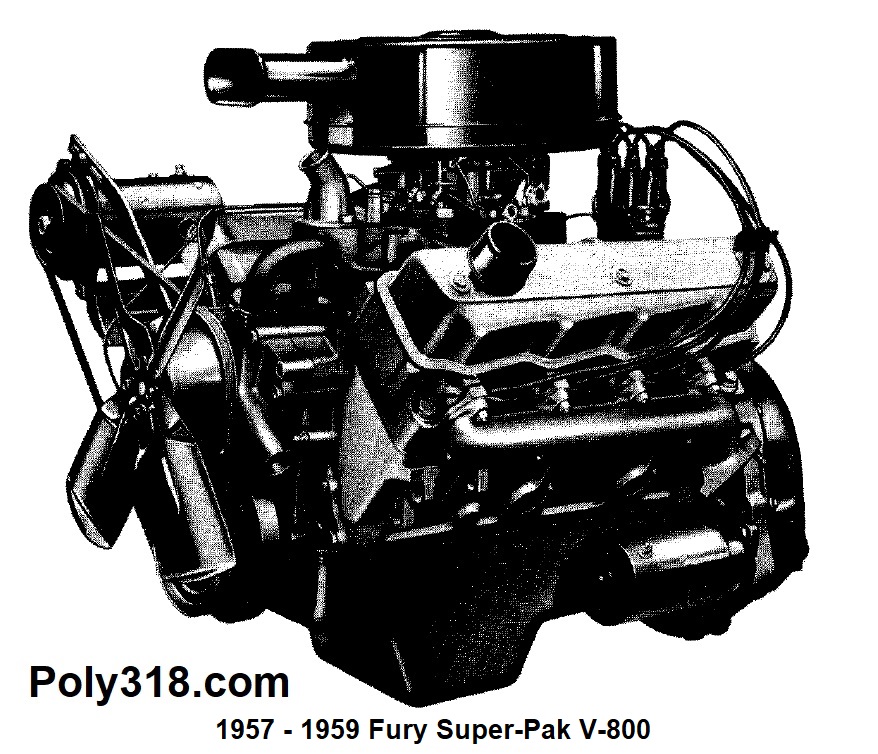
| 1957 | 301 | Car, V800 Super-Pak | 3.91″ | 3.125″ | 8.5:1 | 235 @ 4,400 RPM | 305 @ 2,800 RPM | 1×4 Carburetor. 277 crank and rods, 318 block |
| 1956 | 303 | Fury models and Some Export Models | 3.81″ | 3.31″ | 9.25:1 | 270 @ 5,200 RPM | 310 @ 2,800 RPM | Fury models and some export models |
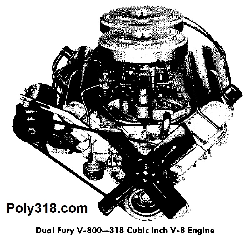
| 1957 to 1958 | 318 | Car, Dual Fury V800 | 3.91″ | 3.31″ | 9.25:1 | 290 @ 5,400 RPM | 225 – 330 @ 3,600 RPM | 2×4 Carburetors |
| 1959 | 318 | Dodge Truck “Power Giant HD” | 3.91″ | 3.31″ | 8.25:1 | 207 @ 4,400 RPM | 292 @ 2,400 RPM | Domestic trucks only |
| 1959 | 313 | Export Truck | 3.875″ | 3.31″ | 7.75:1 | 184 @ 4,400 RPM | 278 @ 2,400 RPM | Export Dodge trucks |
| 1957 to 1962 | 318 | Car, Light Truck, Fury V800 Super-Pak | 3.91″ | 3.31″ | 9.0:1 | 250 – 260 @ 4,400 RPM | 340 – 350 @ 2,600 – 2,800 RPM | 1×4 Carburetor |
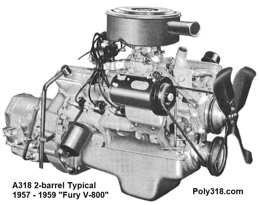
| 1957 to 1967 | 318 | Car, Light Truck, Fury V800 | 3.91″ | 3.31″ | 9.0:1 | 225 – 230 @ 4,400 RPM | 330 – 340 @ 2,400 – 2,800 RPM | 1×2 Carburetor, “Standard” with rare option of “Semi-premium” package |
| 1957 | 301 | Export, V800 Super-Pak | 3.91″ | 3.125″ | 8.5:1 | 235 @ 4,400 RPM | 305 @ 2,800 RPM | Export Market, 1×4 Carburetor. 277 connecting rods |
| 1959 | 326 | Car, Dodge | 3.95″ | 3.31″ | 9.2:1 | 255 @ 4,400 RPM | 350 @ 2,400 RPM | Called the “Red Ram” Standard in Dodge Coronet |
| 1960 | 318 | Heavy Truck | 3.91″ | 3.31″ | 8.25:1 | 200 @ 3,900 RPM | 286 @ 2,400 RPM | Heavy Dodge truck |
| 1961 to 1967 | 318 | Heavy Truck, Low Compression | 3.91″ | 3.31″ | 7.5:1 | 200 @ 3,900 RPM | 286 @ 2,400 RPM | “Full-premium” package |
| 1956 to 1957 | 303 | Export, V800 Super-Pak | 3.81″ | 3.31″ | 9.25:1 | 240 @ 4,400 RPM | 310 @ 2,800 RPM | Export Market, 1×4 Carburetor. |
| 1957 to 1964 | 313 | Export (not Bristol) | 3.875″ | 3.31″ | 9:1 | 225 @ 4,400 RPM | 330 @ 2,400 – 2,800 RPM | Export Market, 1×2 Carburetor |
| 1961 – 1965 | 313 | Export Bristol | 3.875″ | 3.31″ | 9:1 | 240 @ 4,400 RPM 250 @ 4,400 RPM | 330 @ 2,400 – 2,800 RPM 340 @ 2,400 – 2,800 RPM | 1×2 or 1×4 Carburetor Offered |
| 1965 to 1967 | 318 | Export | 3.91″ | 3.31″ | 9:1 | 225 – 230 @ 4,400 RPM | 330 – 340 @ 2,400 – 2,800 RPM | Export Market, 1×2 Carburetor |
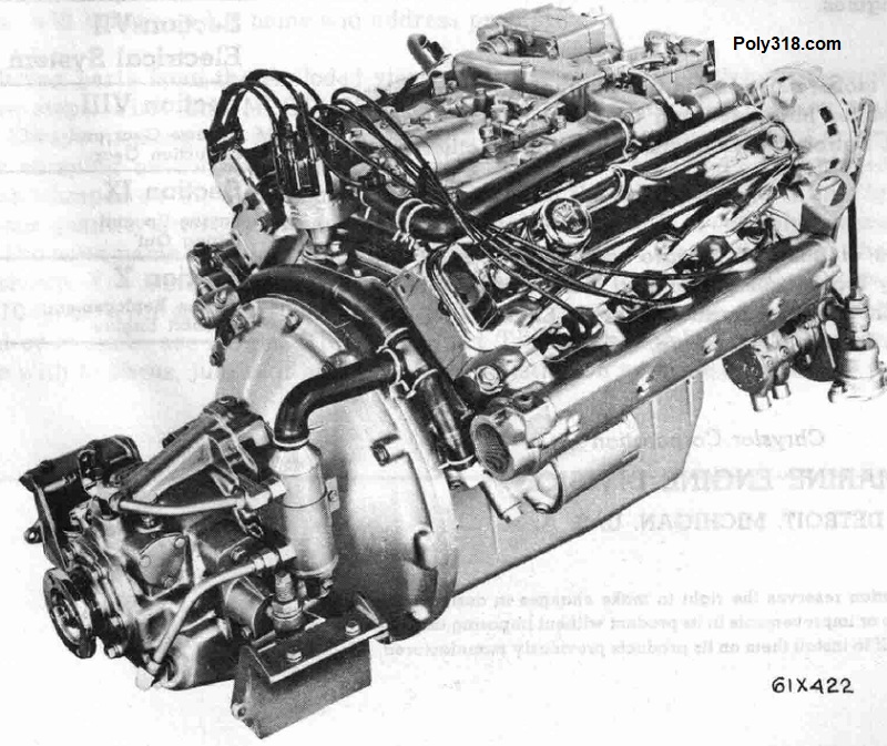
| 1959 to 1963 | 318 | Marine Chrysler Sea V | 3.91″ | 3.31″ | 8.2:1 | 177 @ 3,600 RPM | Unlisted | Torque likely around 250 @ 4,000. See the marine page for details.See marine and industrial engine page |
| 1959 to 1962 | 318 | Marine M318A Fury 190 | 3.91″ | 3.31″ | 8.2:1 | 190 @ 4,000 RPM | 270 @ 4,000 RPM | See marine and industrial engine page |
| 1962 to 1967 | 318 | Marine Fury 195 | 3.91″ | 3.31″ | 8.2:1 | 195 @ 4,000 RPM | 275 @ 4,000 RPM | See marine and industrial engine page |
| 1962 to 1967 | 318 | Marine Fury 210 | 3.91″ | 3.31″ | 8.2:1 | 210 @ 4,000 RPM | 290 @ 4,000 RPM | See marine and industrial engine page |
| 1959 to 1967 | 318 | Marine Fury 235 | 3.91″ | 3.31″ | 8.2:1 | 235 @ 4,000 RPM | Unlisted, likely around 340 @ 4,000 RPM | See marine and industrial engine page |
| 1959 to 1967 | 318 | Industrial H318 | 3.91″ | 3.31″ | 8.2:1 | 190 @ 4,000 RPM | Not listed | Light duty “Standard” package. See marine and industrial engine page |
| 1959 to 1967 | 318 | Industrial HB318 | 3.91″ | 3.31″ | 8.2:1 | 190 @ 4,000 RPM | Not listed | Medium duty “semi-premium” package. See marine and industrial engine page |
| 1959 to 1967 | 318 | Industrial HC318 | 3.91″ | 3.31″ | 8.2:1 | 190 @ 4,000 RPM | Not listed | High-compression medium-duty model. The Industrial manual specs might have two typos for the compression ratio and BHP. The engine is likely 9:1 compression and higher BHP rating. See marine and industrial engine page |
| 1959 to 1967 | 318 | Industrial HT318 | 3.91″ | 3.31″ | 8.2:1 | 193 @ 4,000 RPM | Not listed | Heavy Duty “Full-premium” package. See marine and industrial engine page |
Engine Identification Number Stamped Prefix Specifications
- “1” after the ID denotes a “Standard” engine package:
- This is the most common type of engine found in cars and light trucks.
- Received 9:1 or 8.25:1 compression pistons, steel-backed babbitt bearings, standard timing set, standard volume/pressure oil pump, 4-quart oil pan (1956 – 1958 received a 5-quart oil pan), mechanical flat-tappet camshaft and lifters, adjustable rocker arms, Silchrome intake valves, standard valve-spring retainers and springs, standard distributor.
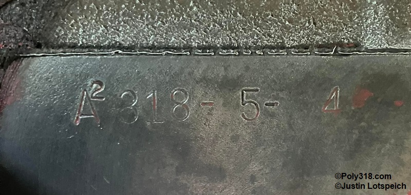
- “2” after the ID denotes a “Semi-premium” engine package.
- The number 2 may also be a superscript after the ID (Figure 1a).
- These engines when found are often in Dodge light trucks (D/W100, D/W200, D300).
- These engines usually received 8.25:1 compression pistons, steel-backed babbit crank and rod bearings, “silent” plastic-teeth timing set, standard pressure/volume oil pump, 4-quart oil pan, mechanical camshaft and lifters, adjustable rocker arms, Silchrome intake valves, standard valve retainers and springs, standard distributor.
- “3” after the ID denotes a “Full-premium” engine package.
- The number 3 may also be a superscript after the ID similar to Figure 1a.
- These engine are not common compared to the total production numbers of the A318 and were available standard in Dodge heavy trucks including D400, D500, D600, W300, and W500, Travco motorhomes, and optional in light trucks. The share most of the same components as the industrial HT318 heavy duty engines.
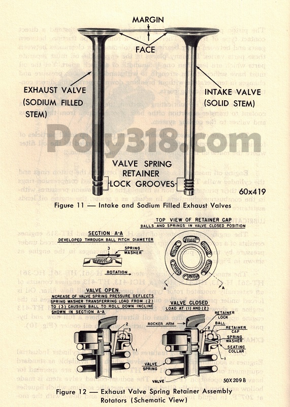
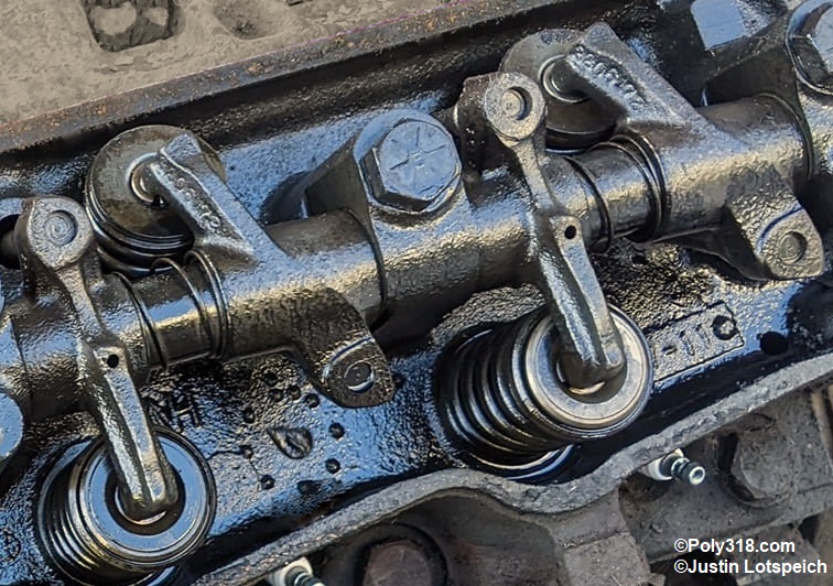
- These engines received 7.5:1 or 8.25:1 compression pistons, tri-metal crank and rod bearings, roller timing set, high-pressure (standard volume) oil pump, 5-quart oil pan, hardened and shot-peened forged crankshaft, hydraulic camshaft and lifters, non-adjustable rocker arms, Silchrome intake valves, Stellite-faced exhaust valves, sodium-cooled/filled exhaust valves, exhaust valve rotators, special valve springs for rotators (Figures 1b – 1c), and standard distributor.
Detailed Mechanical Specs for Poly 313, 318, 326
| Category | Component | Specification | Notes |
|---|---|---|---|
| Block | Cylinder Out-of-Round | No more than 0.005” before overbore, and that is very worn. | |
| Cylinder Taper | No more than 0.020” before overbore, and that is very worn. | ||
| Lifter Bore Diameter | 0.9050” – 0.9058” allowable | See oiling modification tech article | |
| Cylinder Pressure, Stock Build | 120 – 150 cranking psi, no greater than 20 psi variation between cylinders. 110 psi minimum. | Cylinder pressure depends greatly on elevation, climate conditions, compression ratio, cam, testing procedure, and component wear. | |
| Cylinder Pressure, Performance Build | Above 160 cranking psi ideal, no greater than 20 psi variation between cylinders. | Cylinder pressure depends greatly on elevation, climate conditions, compression ratio, cam, testing procedure, and component wear. | |
| Deck Height | 9.603″ | The deck height can vary from block to block depending on core shift and if the block has ever been milled before. When milling the block to square the surfaces, most blocks clean up at .015″ – .020″. You can usually go up to .040″ before needing to also machine the intake manifold. | |
| Camshaft | End Play | 0.002” – 0.006” with 0.010 max | |
| Bearing Clearance | 0.001” – 0.003” with 0.005 max | ||
| Journal 1 Diameter | 1.998″ – 1.999″ | Important for measuring core shift | |
| Journal 2 Diameter | 1.982″ – 1.983″ | Important for measuring core shift | |
| Journal 3 Diameter | 1.967″ – 1.968″ | Important for measuring core shift | |
| Journal 4 Diameter | 1.951″ – 1.952″ | Important for measuring core shift | |
| Journal 5 Diameter | 1.5605″ – 1.5615″ | Important for measuring core shift | |
| Bearing 1 Diameter | 2.000″ – 2.001″ | ||
| Bearing 2 Diameter | 1.984″ – 1.985″ | ||
| Bearing 3 Diameter | 1.969″ – 1.970″ | ||
| Bearing 4 Diameter | 1.953″ – 1.954″ | ||
| Bearing 5 Diameter | 1.5625″ – 1.5635″ | ||
| Cooling System | Capacity w/out heater | 20 quarts typical | Depends on radiator and heater core size. See cooling system tech articleSee cooling system tech article |
| Radiator Cap Relief | 14 – 16 psi (higher with A/C) | 1956 – 1959 used 12 psi cap. See cooling system tech articleSee cooling system tech article | |
| Thermostat | 180° or 195° | See cooling system tech articleSee cooling system tech article | |
| Normal Operating Temperature | 175° – 205° | See cooling system tech articleSee cooling system tech article | |
| Crankshaft, Con Rods | Main Journal Diameter | 2.4995” – 2.5005” | |
| Main Journal Out-of-round and Taper | 0.001″ maximum | ||
| Main Bearing Clearance | 0.0005” – 0.0025” | ||
| #3 Thrust Bearing Run-out | 0.002″ | ||
| Crankshaft End Play Measured at Bearing #3 | 0.002” – 0.007” | ||
| Rod Journal Diameter | 2.124” – 2.125” | ||
| Rod Journal Out-of-round and Taper | 0.001 maximum | ||
| Rod Bearing to Journal Clearance | 0.0005” – 0.0025” | ||
| Rod Bearing Side Clearance | 0.006″ – 0.014″ | ||
| Rod Length | 6.123” | ||
| Rod Journal Bearing Diameter and Width | 2.126″ x 0.842″ | ||
| Rod Pin Journal Diameter | 0.9842 – 0.9843″ | Bronze bushing | |
| Piston Pin to Rod Clearance | 0.0001″ – 0.0004″ | ||
| Rod Ratio | 1.85 | ||
| Fueling | Fuel Pressure | 5 psi – 7 psi | When running some Holley (e.g. 4150/4160) and Edelbrock AVS carburetors, pressure over 6.4 psi can lift the needles causing flooding. |
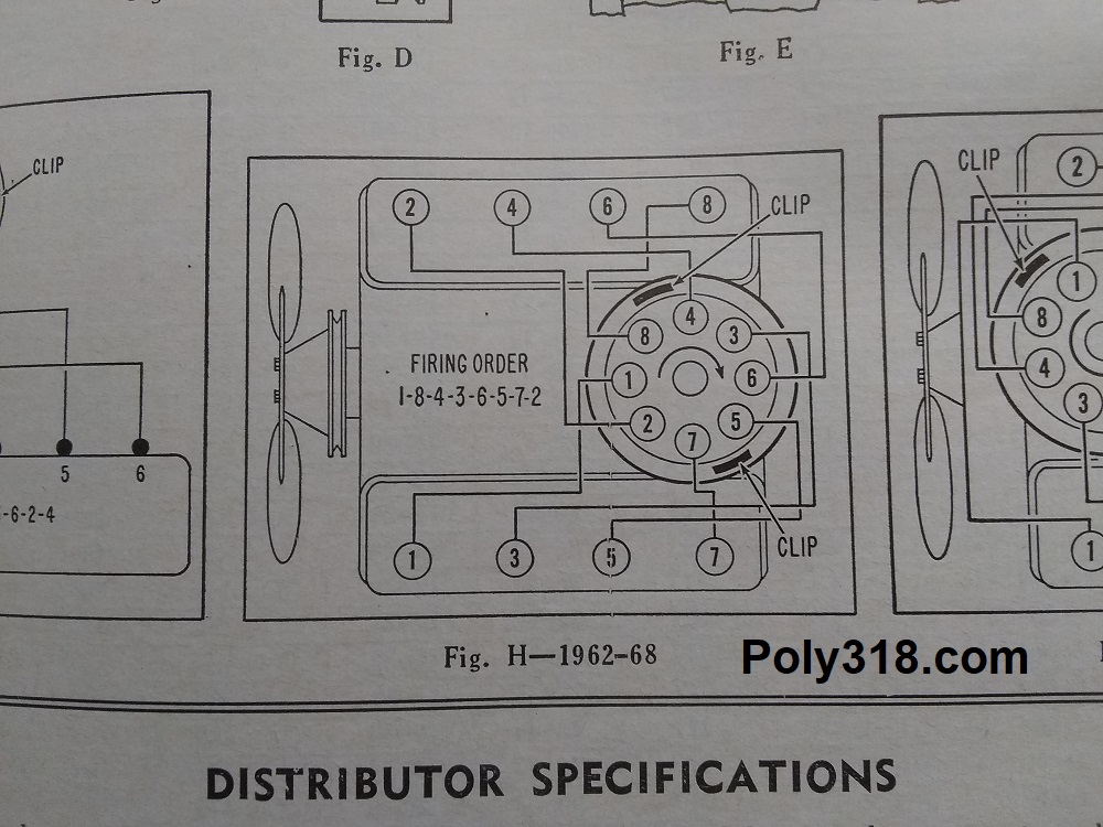
| Ignition | Firing Order (Figure 2) | 18436572 | |
| Hot idle speed | 500 – 850 rpm | Depends on cam and vacuum requirements. See carburetor selection and tuning tech article | |
| Spark Plug Type | 3/8” short-reach | Autolite 85, Champion 63 (formerly J12Y), etc. WARNING: Do not install LA-type 3/4″ long-reach plugs, such as Autolite 65. They will contact the piston. | |
| Spark Plug Gap | 0.035″ | See ignition timing and points adjustment tech article | |
| Points Gap | 0.017” | See ignition timing and points adjustment tech article | |
| Dwell Angle | 26° – 28° ideal, 26° – 32° allowable | See ignition timing and points adjustment tech article | |
| Coil Resistance Primary | 1.65 – 1.79 ohms | at 70°F – 80°F | |
| Coil Resistance Secondary | 8,000 – 9,200 ohms | at 70°F – 80°F | |
| Ballast Resistor | 0.665 – 0.735 ohms | ||
| Distributor Shaft to Bushing Clearance | 0.0007″ – .0027″ | ||
| Distributor Shaft Side Play | 0.000″ – 0.003″ | Wear over 0.006″ requires rebuilding | |
| Distributor Shaft End Play | 0.003″ – 0.017″ | Check with distributor installed and clamped down. Note that it is common to find the end play outside the factory tolerance on even NOS and quality new aftermarket distributors up to 0.050″, which will not impact the distributor negatively. Excessive end play should be diagnosed and addressed since it may cause wear to the drive tang leading to inconsistent timing and possibly breakage. | |
| Ignition Timing | Initial | 10° BTDC | Baseline for starting engine in order to tune. See ignition timing and points adjustment tech article |
| Total Advance w/out vacuum at 4,000 RPM | 34° – 36° | Depends on each engine. See ignition timing and points adjustment tech article | |
| Total Advance with vacuum at 4,000 RPM | 44° – 56° | Depends on each engine. See ignition timing and points adjustment tech article | |
| Adjustable Vacuum Advance Screw Midpoint | 5 turns out from full in (typical) | Verify with specific vacuum can | |
| Lifters | Lifter Angle | 59° | |
| Lifter Diameter | 0.9040″ – 0.9045″ | ||
| Lifter Bore | 0.9050″ – 0.9058″ | ||
| Lifter Bore Spacing | 1.760″ | ||
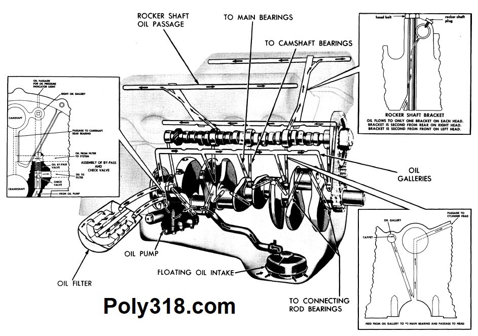
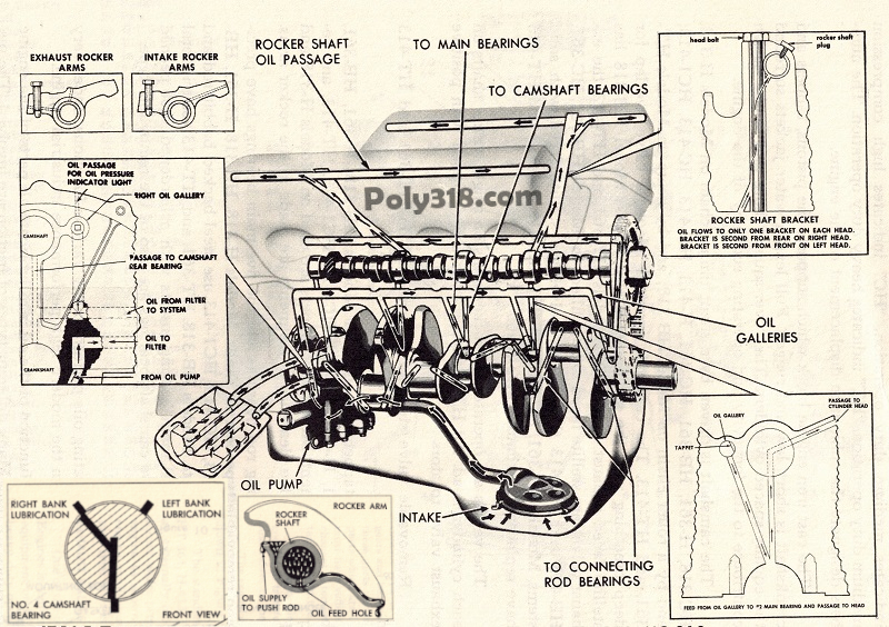
| Oil System (Figures 3a – 3b) | Hot Oil Pressure at Idle under 800 RPM | 20 – 30 psi ideal | Lower than 20 psi idle suggests an oiling problem |
| Hot Oil Pressure above 1,500 RPM | 50 psi – 65 psi | High-pressure pumps may run 70 – 75 psi | |
| Capacity 1956 – 1958 with 5-quart Pan | 5 quarts, 6 total with filter | ||
| Capacity 1959 – 1967 with 4-quart Pan | 4 quarts, 5 total with filter | ||
| Capacity 1959 – 1967 Marine with 8-quart Pan | 8 quarts, 9 total with filter | ||
| Capacity 1956 – 1967 Industrial with 5-quart Pan | 5 quarts, 6 total with single filter, 7 total with dual filters | ||
| Viscosity, Rebuild Break-in | 30 weight conventional with ZDDP. | WARNING: Never use synthetic oil to seat new rings. Always use a ZDDP formula or additive with flat-tappet camshaft/lifters. | |
| Viscosity, Cold Climates below 40°F | 5W30 conventional or synthetic with ZDDP. | WARNING: Always use a ZDDP formula or additive with flat-tappet camshaft/lifters. | |
| Viscosity, Cold and Mild Climates between 41°F – 90°F | 10W30 or 10W40 conventional or synthetic with ZDDP. | WARNING: Always use a ZDDP formula or additive with flat-tappet camshaft/lifters. | |
| Viscosity, Very Hot Climates above 90°F | 10W40 or 20W50 conventional or synthetic with ZDDP. | WARNING: Check hydraulic lifter specs since performance lifters often specify no thicker than 10W30. Always use a ZDDP formula or additive with flat-tappet camshaft/lifters. | |
| Rebuild Oil Priming Prior to Start | Manually prime with high-torque drill. | Figure 5 shows why often times the engine must be turned over by hand while priming the oiling system because the camshaft must rotate to feed both cylinder heads galleries. | |
| Oil Pump Cover Flat, 1956 – 1967 M51 and M72 | 0.0015″ maximum | See oil pump blueprinting tech article | |
| Oil Pump Inner and Outer Rotor to Cover, 1956 – 1967 M51 and M72 | 0.001″ – 0.004″ | See oil pump blueprinting tech article | |
| Inner Rotor to Outer Rotor Teeth, 1956 – 1961 M51 | 0.001″ maximum | Feeler gauge placed between teeth. See oil pump blueprinting tech article Note that the M72 clearance of 0.001″ – 0.006″ may be safely used for the M51 pump. | |
| Inner Rotor to Outer Rotor Teeth, 1962 – 1967 M72 | 0.001″ – 0.006″ | Feeler gauge placed between teeth. See oil pump blueprinting tech article | |
| Inner Rotor Height, 1956 – 1961 M51 | 0.998″ minimum | ||
| Outer Rotor to Pump Housing, 1956 – 1967 M51 and M72 | 0.002″ – 0.012″ | See oil pump blueprinting tech article | |
| Outer Rotor Diameter, 1956 – 1961 | 2.244″ minimum | ||
| Outer Rotor Height, 1956 – 1961 | 0.998″ minimum | ||
| Pistons | Clearance Top of Skirt | 0.0005” – 0.0015” | |
| Ring End Gap | Depends on ring manufacturer, induction type, and build purpose. Factory street is 0.015” for compression and scraper | Always follow ring manufacturer specs. | |
| Floating Wrist Pin Diameter and Length | 0.9842″ x 2.995″ | ||
| Pin to Piston Clearance at 70°F | 0.00 – 0.0005″ | Use light thumb push to measure | |
| End Play | 0.004″ – 0.026″ | ||
| Piston Pin to Rod Clearance | 0.0001″ – 0.0004″ | ||
| Rocker Arms | Rocker Arm Ratio | 1.5:1 | |
| Arm to Shaft Clearance | 0.001″ – 0.003″ | See rocker assembly rebuilding tech article | |
| Shaft to Bracket Clearance | 0.001″ – 0.0045″ | See rocker assembly rebuilding tech article | |
| Valves | Intake Diameter | 1.844″ | |
| Intake Length | 4.599″ | ||
| Intake Stem Diameter | 0.3725″ | ||
| Intake Stem Clearance | 0.001” – 0.003” | ||
| Intake to Piston Clearance | 0.080″ minimum | ||
| Intake Tip Length | 0.213″ | ||
| Intake Keeper | 7° | ||
| Exhaust Diameter | 1.563″ | ||
| Exhaust Length | 4.539″ | ||
| Exhaust Stem Diameter | 0.3715″ | ||
| Exhaust Stem Clearance | 0.002” – 0.004” | ||
| Exhaust to Piston Clearance | 0.100″ minimum | ||
| Exhaust Tip Length | 0.0989″ | ||
| Exhaust Keeper | 7° 4-groove | ||
| Valve Adjustment | Mechanical Lifter Intake Lash Hot | 0.013” | See valve adjustment tech articleSee valve adjustment tech article |
| Mechanical Lifter Exhaust Lash Hot | 0.021” | See valve adjustment tech articleSee valve adjustment tech article | |
| Mechanical Lifter Intake Cold (for initial start) | 0.015″ | See valve adjustment tech articleSee valve adjustment tech article | |
| Mechanical Lifter Exhaust Cold (for initial start) | 0.023″ | See valve adjustment tech articleSee valve adjustment tech article | |
| Hydraulic Lifter Intake and Exhaust Preload Hot | 3/4 turn after zero lash | See valve adjustment tech articleSee valve adjustment tech article | |
| Hydraulic Lifter Intake and Exhaust Preload Cold (for initial start) | 1/2 turn after zero lash | See valve adjustment tech articleSee valve adjustment tech article | |
| Valve Springs | Valve Spring Installed Height | 1.7” | Verify proper rocker arm tip position |
| Valve Spring Pressure Factory Spec. | up to 145 in. lbs. at 1-5/16” | Follow camshaft’s required spring pressure |