Poly 318 Cylinder Head Porting
(applicable to 277, 301, 303, 313, 318, and 326)
Introduction
This article is part of my larger engine-building series and focuses on porting heads at home for performance A-blocks. The A-block polyspherical combustion chamber design is excellent in many ways despite its short-lived use from the 1950s – 1966 until its reemergence in some 21st century engines. By the 1960s, Mopar likely restricted the design to A-blocks and abandoned it in 1966 due to the higher cost of production compared to wedge heads.
Of note, when compared to LA340 and LA360 wedge-head intake and exhaust runners, A-block runners appear small; however, it is important to remember that the polypherical combustion chamber design and combustion physics do not require runners as large as wedge heads. Still, A-block heads benefit from increased valve diameter, port matching, and full porting. Even modest hand porting done by a competent, careful mechanic at home feeds engines up to 450 HP. For the faint of heart not yet ready to dive into full porting, port matching will see cheap power gains since the intake and exhaust manifold ports are decently misaligned from the head ports.
In the case of the heads I’m using on my 390 stroker build, I chose to increase the valves to 2.02” intake, 1.60” exhaust, race valve job, and full hand porting. In this article, I detail how I went about porting the heads at home with a quality high-volume air compressor, die grinder, long-reach carbide bits (ball, rounded cylinder, and tapered point), stones, 80-grit sanding barrels, moveable light source, and container of water to cool the carbide bit. I do not have a flow bench to test the heads, like many hot rodders before me, but focus on pinch and turbulence points that people who have flowed A-block heads have discussed with me in depth. The key is to focus on matching the runners to the gaskets and porting back keeping the runner corners as uniform and open as possible, removing/smoothing as many humps in the casting as possible, and maintaining good taper into the bowls. Attention to the short and long turns of the bowls is critical as well. A light touch and working slowly and deliberately is key.
My intent in this article is to demonstrate what competent hot rodders who like to do their own work can do at home to get substantial improvement in performance without dropping thousands of dollars on a flow bench/software or with a professional porter. If I were looking to build a 600 HP A-block, I would likely spend the money building a flow bench or as a last resort farm out the task to a reputable A-block porter to get every bit out of the heads. I list three different porters in the flow numbers below.
I break this article into three parts: work I did before having my machinist cut the larger valves and install new guides, work after the preliminary valves job and guide, and work after the valve job was completed. The runners and a portion of the bowls can be ported prior to any valve work to lower the risk of damaging the new seats but leaving the machinist plenty of meat for the new seats and guides. After that work is completed, I go back in and blend the bowls and sand the bowls and runners. After the valve job is completed, I go in and do any final touchups.
Flow Comparisons
The following flow numbers at 28” water demonstrate the differences in CFM between factory and degrees of porting by different porters.
Stock A-block (courtesy Total Performance for Gary Pavlovich)
- Intake Valve: 1.85”
- Exhaust Valve: 1.55”
- Valve Stem: 3/8” no undercut
| LIFT (INCHES) | INTAKE (CFM) | EXHAUST (CFM) |
| .100 | 51 | 46 |
| .200 | 117 | 83 |
| .300 | 150 | 106 |
| .400 | 172 | 127 |
| .500 | 184 | 142 |
| .550 | 187 | 147 |
Hand Ported 1 (courtesy Total Performance for Gary Pavlovich)
- Intake Valve: 2.02”
- Exhaust Valve: 1.60”
- Valve Stem: 3/8” no undercut
| LIFT (INCHES) | INTAKE (CFM) | EXHAUST (CFM) |
| .100 | 70 | 49 |
| .200 | 145 | 88 |
| .300 | 189 | 113 |
| .400 | 203 | 134 |
| .500 | 211 | 151 |
| .550 | 216 | 158 |
Hand Ported 2 (courtesy Douglas Porting Service)
- Intake Valve: 2.05”
- Exhaust Valve: 1.60”
- Valve Stem: 11/32” undercut
| LIFT (INCHES) | INTAKE (CFM) | EXHAUST (CFM) |
| .100 | 72 | 63 |
| .200 | 144 | 98 |
| .300 | 204 | 123 |
| .400 | 225 | 146 |
| .500 | 240 | 163 |
| .600 | 252 | 171 |
Hand Ported 3 (courtesy Scott Glover)
- Intake Valve: 2.02”
- Exhaust Valve: 1.60”
- Valve Stem: 11/32” undercut
| LIFT (INCHES) | INTAKE (CFM) | EXHAUST (CFM) |
| .100 | 75 | 63 |
| .200 | 158 | 105 |
| .300 | 218 | 130 |
| .400 | 241 | 171 |
| .500 | 250 | 192 |
| .550 | 256 | 198 |
CNC Ported (courtesy Scott Glover)
- Intake Valve: 2.02”
- Exhaust Valve: 1.60”
- Valve Stem: 5/16” undercut
| LIFT (INCHES) | INTAKE (CFM) | EXHAUST (CFM) |
| .100 | 72 | 67 |
| .200 | 141 | 104 |
| .300 | 211 | 133 |
| .400 | 248 | 175 |
| .500 | 263 | 198 |
| .600 | 266 | 217 |
Work Prior to Valve and Guide Machine Work
Disassemble the cylinder head (see my head disassembly technical article). Having a machinist clean and magnaflux the heads before porting can determine if the heads are useable; in the case of these heads, I chose to do most of the porting work prior to having the machinist clean and magnaflux the heads since they visually looked solid and I did not mind practicing porting if the heads turned out to be unusable. As it would turn out, they magnafluxed fine.
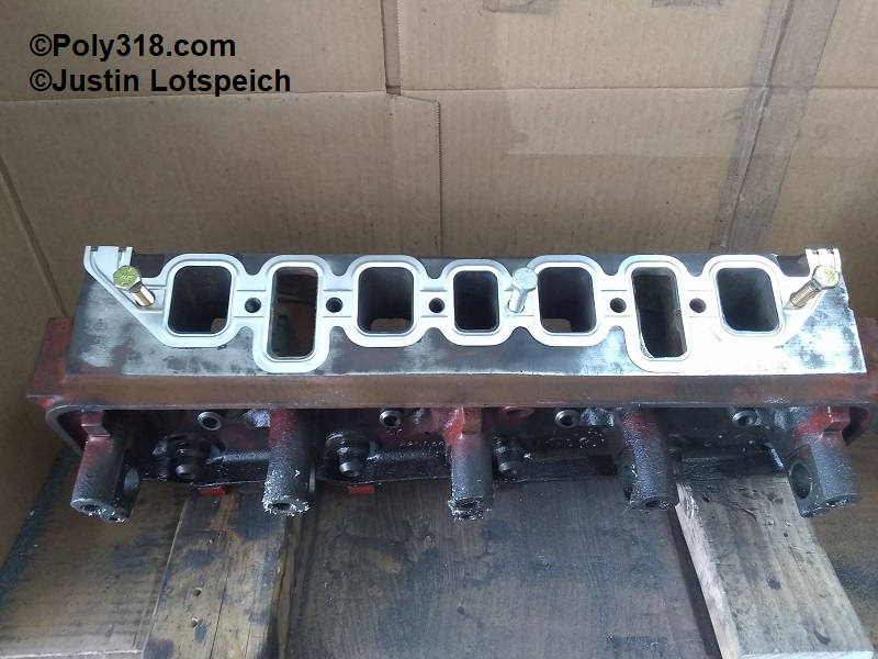
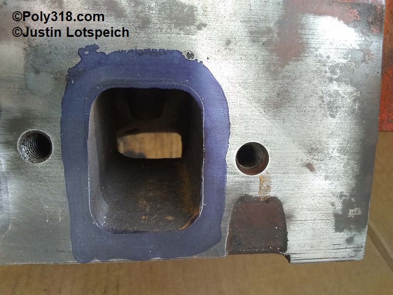
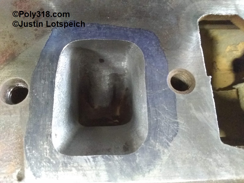
- Focusing on the intake runners first, clean the gasket surface, apply Dykem Blue or similar, and secure with 3/8” bolts the same gasket used to port the intake manifold (see my intake porting technical article). Mark the gasket with a sharp scribe (Figure 1).
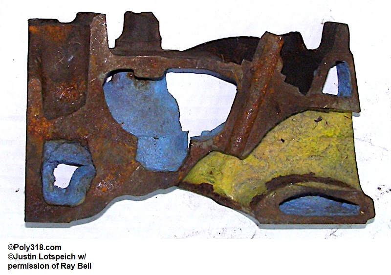
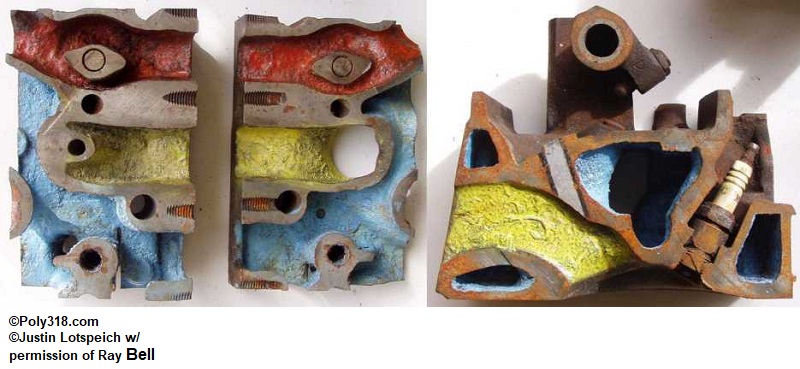
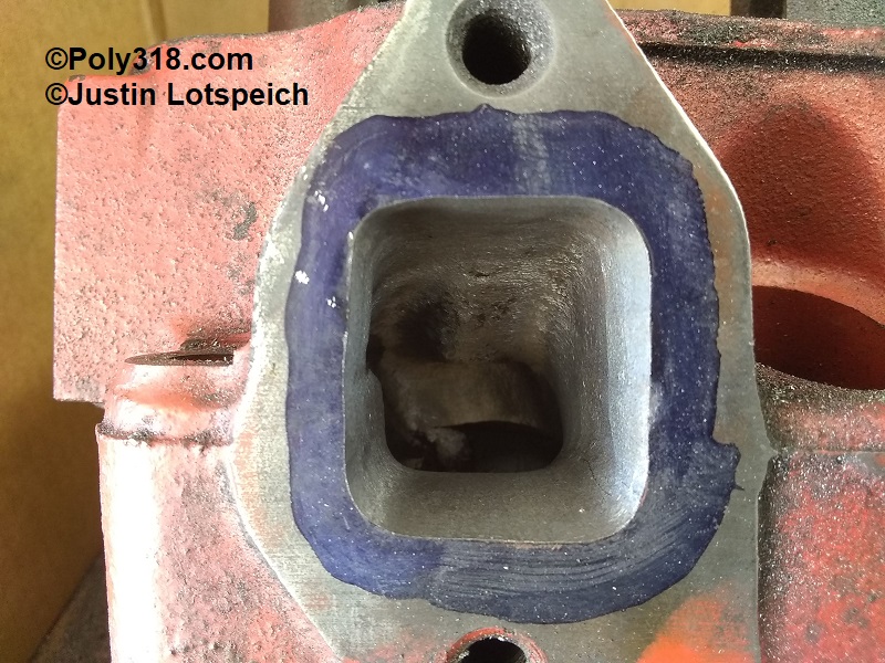
- In Figures 2 and 3, note that most of the material on these heads needs to come off the sides, roof, and corners. The corners, particularly on the floor, have a wide radius that can be tightened to widen the runners and ease the short-turn. Also, note the hump on the floor, referring to the sectionals Figures 3a – 3b. I will address this hump in a following step.
- Using the rounded cylinder bit with the head placed where I can work comfortably on the roof and walls, I begin taking off material from the opening moving toward the bowl evenly. The casting has a crease down the runner walls like the sectional view of an opened book, so I work on taking down the hump on each side of the crease before moving to making sweeps with the bit from floor to roof (Figure 4). I focus on maintaining the gasket corner radius back into the bowl, but be careful not to carve a trough into the floor/roof. I will work all intake runners in this fashion before needing to change bits.
- Once I have the roof and walls (except for the very top corners) close to where I want them, I use a combination of the round and tapered bits to smooth the areas around the guide, being careful not to get tunnel vision and dig into the wall when struggling to reach a spot between the guide and wall from the runner side and instead flip the head to work from the bowl side for access. I leave plenty of material around the guide for the machinist and will go back in and contour after the new guides are installed.
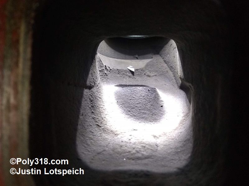
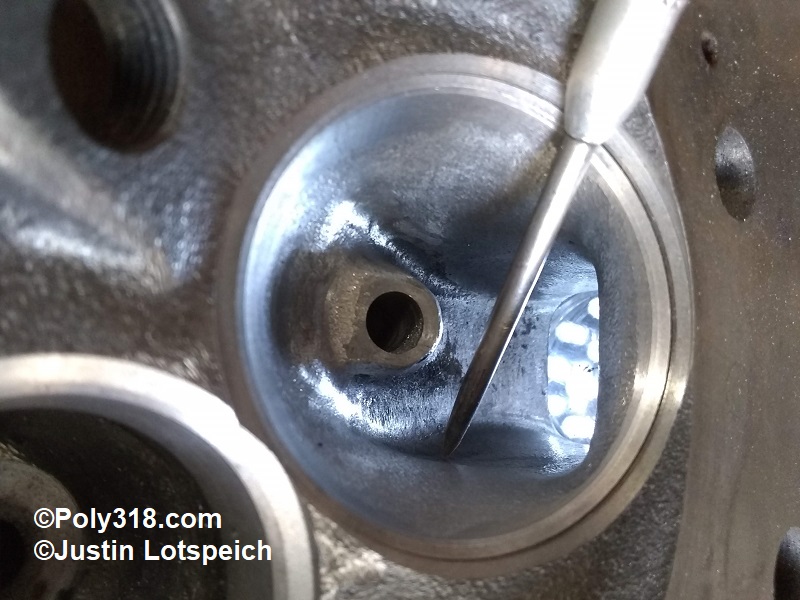
- With the head positioned where I can work comfortably on the floor, I place a permanent-marker dot on the roof above the appendix of the floor hump. I take a measurement from the dot to the floor with a telescoping bore gauge (Figure 5). Using the rounded cylinder bit, I move side to side flattening the hump until I have removed .0625” measured with a feeler gauge (Figure 6).
- Working from the gasket mark back, I remove material from the lower walls and floor keeping the corner radius consistent.
- There will be two sharp angles in the floor, one on each side of the portion I flattened. I smooth these angles and work the short turn down into the bowl using my finger to feel the contour until I am satisfied with the runner porting (Figure 7). I finish the rest of the intake runners in this fashion.
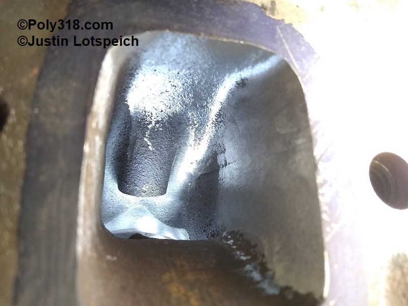
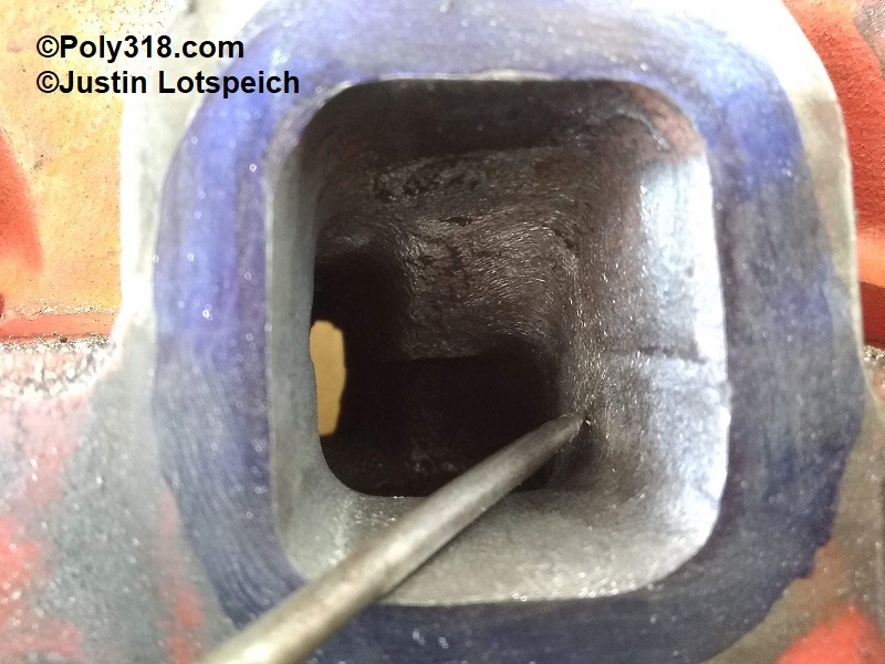
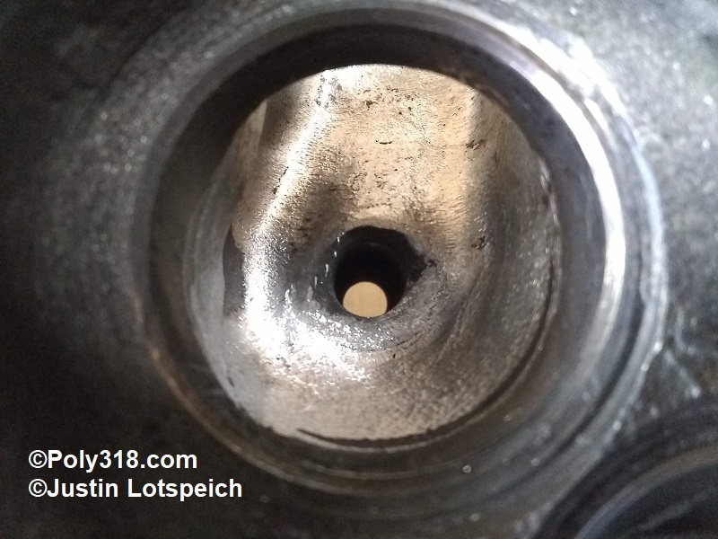
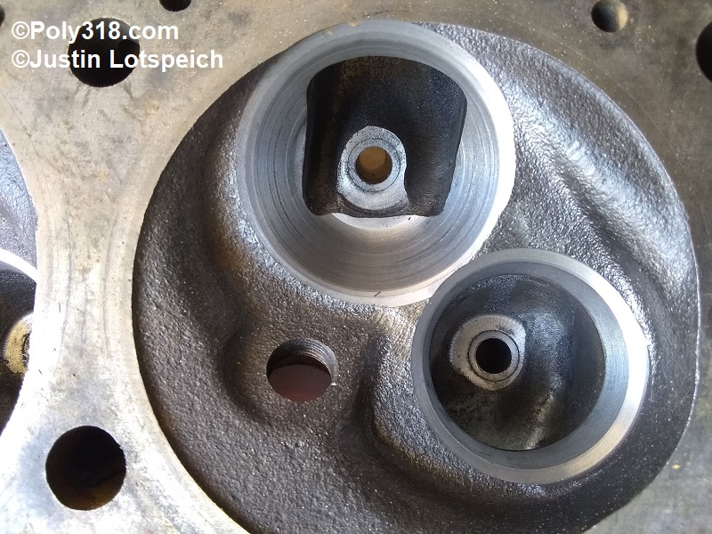
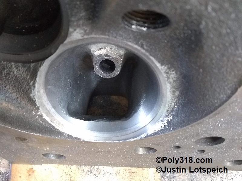
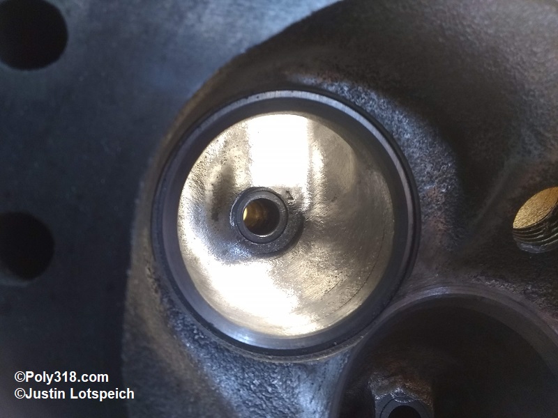
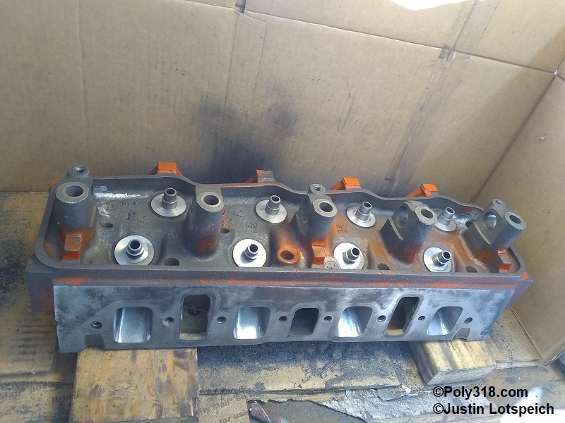
- With the head positioned where I can work comfortably on the chambers and bowls, I note the rough casting/machining and any pinch points (Figure 8). I will leave most of the meat near the seats for the machinist and focus on contouring the areas deeper in the bowl.
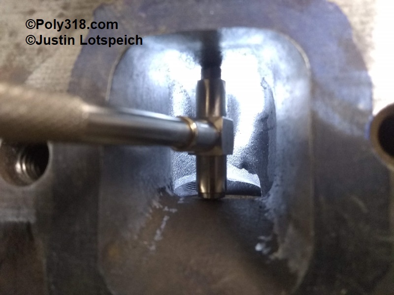
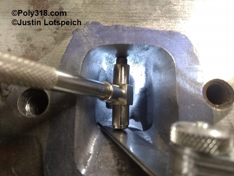
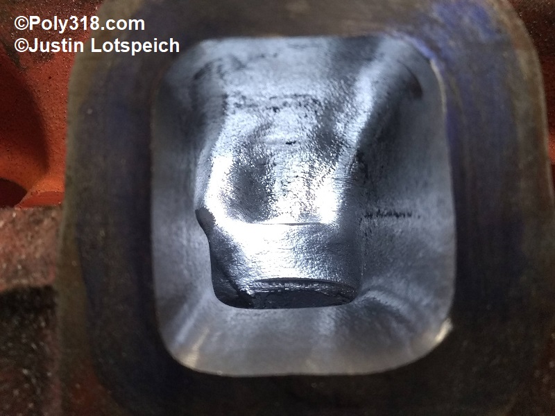
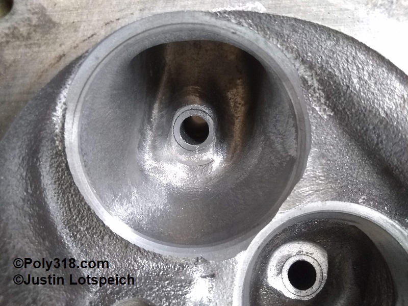
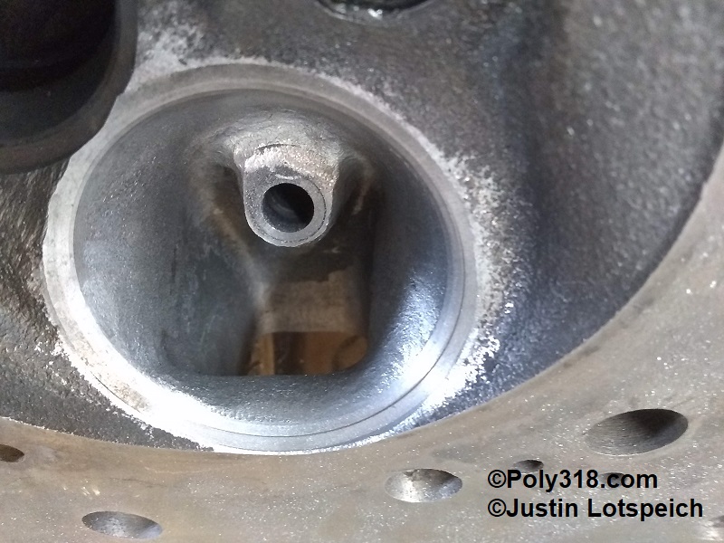
- Using a combination of the ball and rounded cylinder bits, I shape the bowl to smooth out any waves and to contour around the guide. I use the tapered bit to clean up the wall and ceiling on the tight side of the guide. At this point, the bowl is finished until I complete contouring after the new seats and guides are installed (Figure 9).
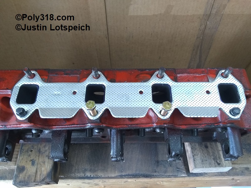
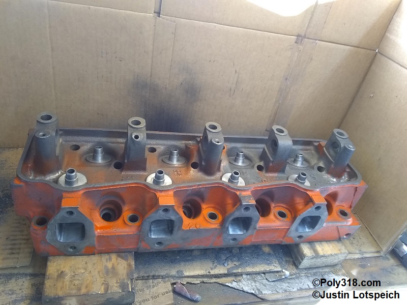
- Clean the exhaust gasket surface, apply Dykem Blue or similar, and secure the exhaust gasket with 3/8” bolts. Mark the gasket with a sharp scribe (Figure 10).
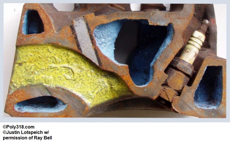
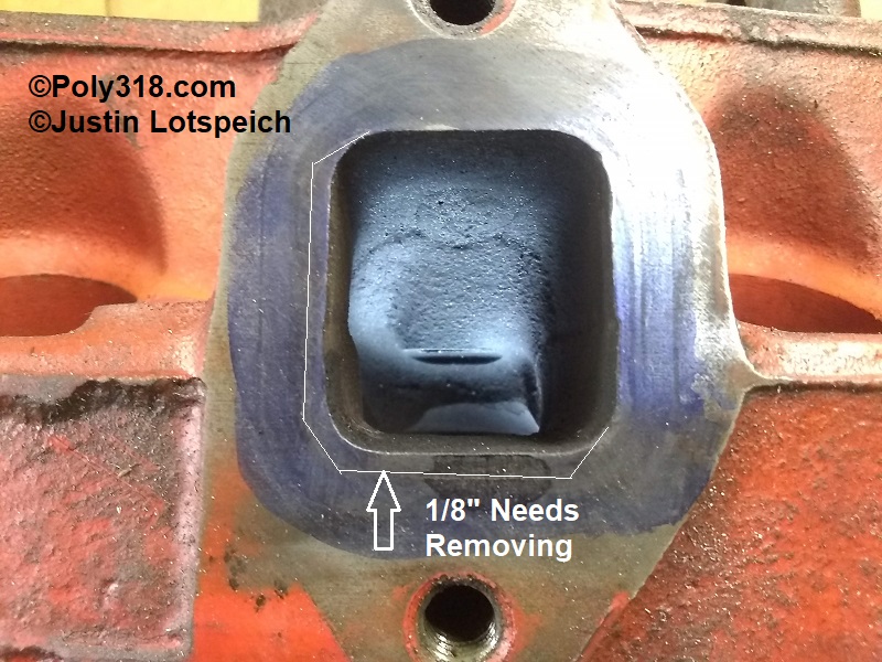
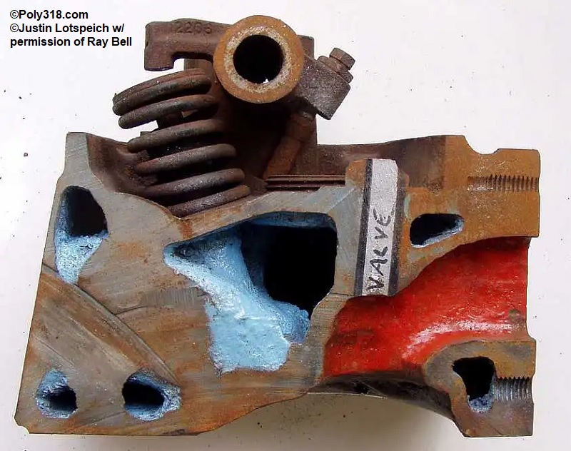
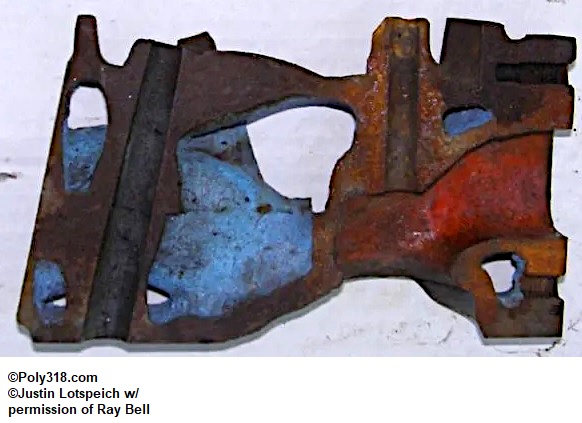
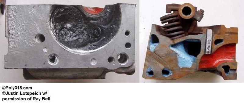
- In Figure 11, note that the exhaust runners on these heads require removing a lot of material with 1/8” typically needed from the floor and one side. However, the sectional Figures 12a – 12c shows that there is not much material between the floor and water jacket near the short turn.
- To address the floor, I use the rounded cylinder bit to remove 1/16” off the entire floor back to the turn and the remaining material off the thickened gasket flange, creating a very slight hump in the floor since I want to keep the floor as thick as possible to stay away from hotspots and cracking from the exhaust temperature. I ease the transition from the floor through the short turn, using my finger to feel the contour.
- Working up the walls, I open up to the gasket line. In the case of these heads, the runners shrunk inward at the gasket flange, so opening up the wall to the gasket line actually straightened out what had been a bulge in the runner. Keep the gasket corner radius consistent all the way trough the short turn.
- In Figure 13, note the bulge in the wall above the short turn. While I do not take out all of the bulge, I flatten it considerably and smooth it. Also note that the walls have a crease similar to the intake runners, but I cannot remove all of this crease without creating a bulge in the runner that will pinch down at the gasket; I smooth out the crease and leave it.
- In Figure 14, note the shelf in the bowl. From all the flow tests I know of, this shelf does not impact flow for street porting, so I simply ease the edges and leave it.
- With the head positioned where I can comfortably work on the roof, I flatten the roof and radius the corners to the gasket line, carrying the corner radius into the bowl.
- Similar to the intake side, I use a combination of the ball and rounded cylinder bits to smooth out and around the guides leaving most material for after the new guides are installed. At this point, the runners are completed until after the new seats and guides are installed where I will finish working the guides and sand the runners (Figures 15 and 16).
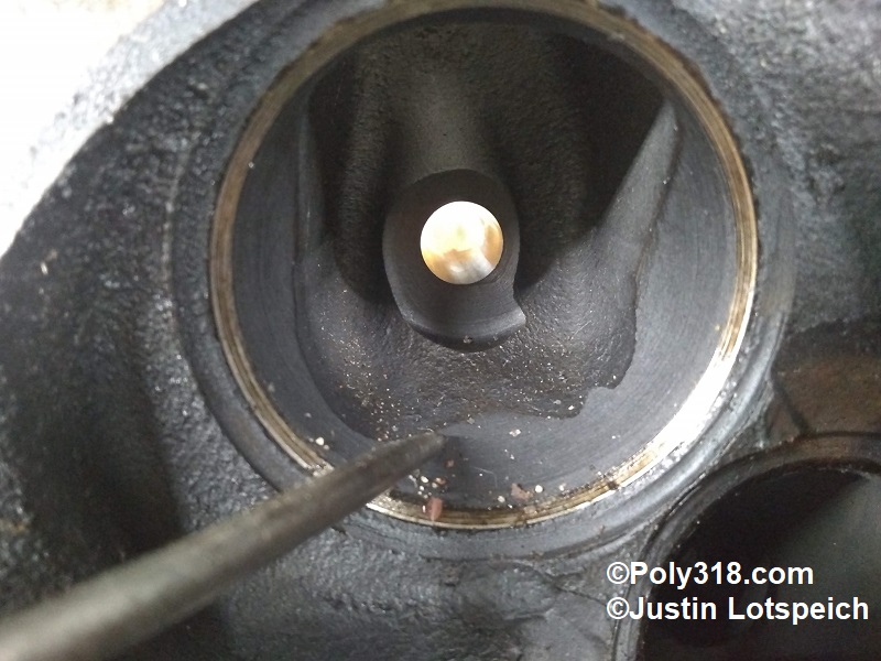
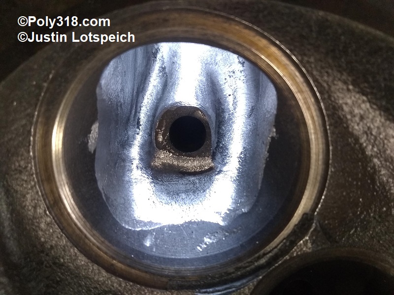
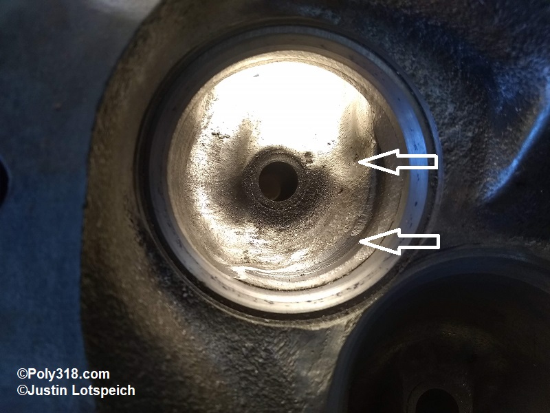
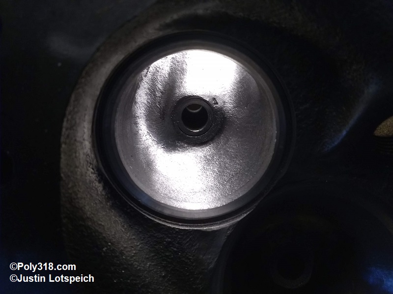
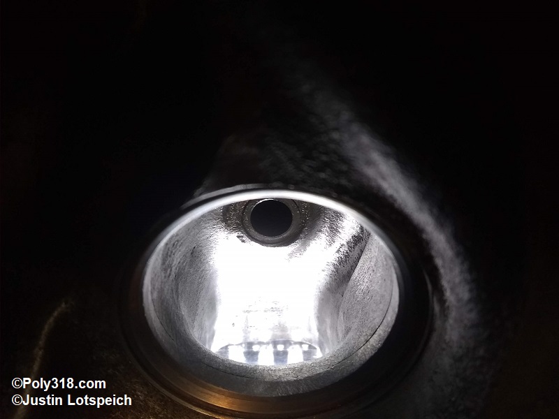
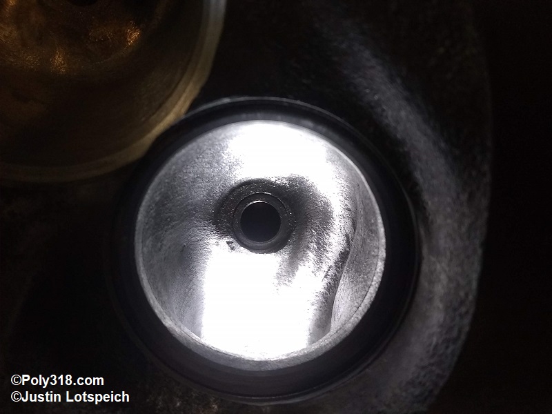
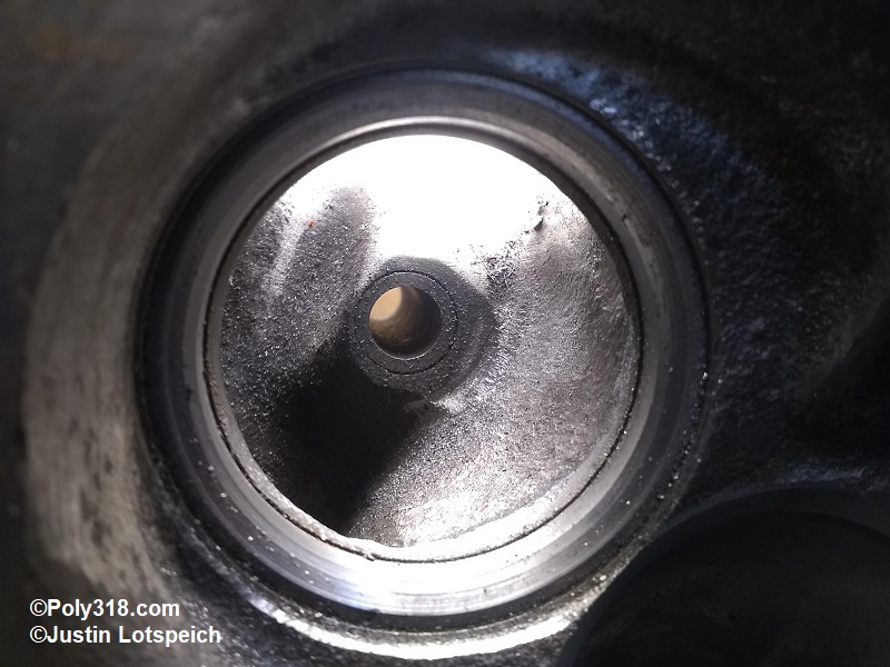
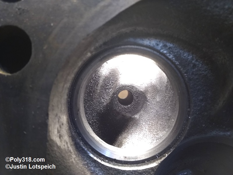
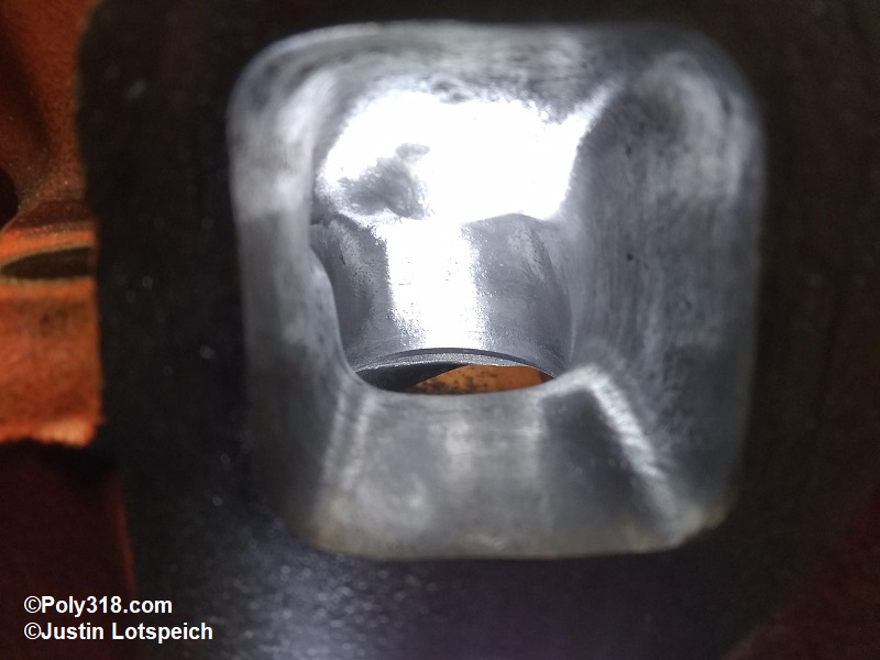
- With the head positioned where I can work on the chamber and bowls, I note the severe obstructions in the bowls (Figures 17 and 18). Using the ball bit, I remove much of the shelf tapering from the seat to the guide but leaving meat for the machinist. I use the tapered bit to remove the sharp edge at the guide keeping most of the guide meat for the machinist. At this point, the bowls are completed until after the new seats and guides are installed (Figure 19).
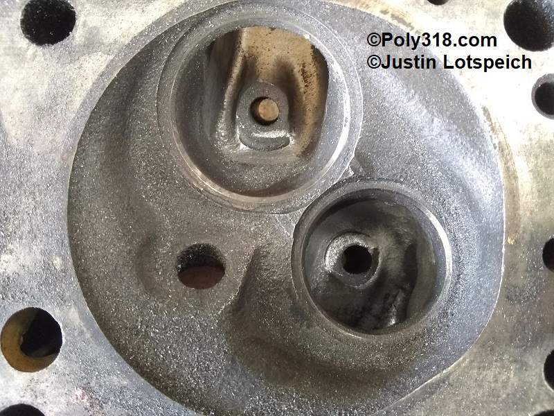
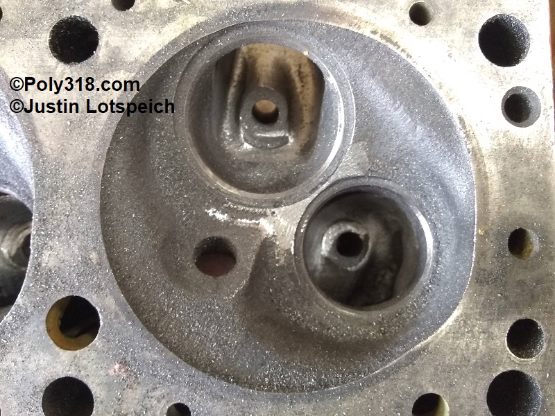
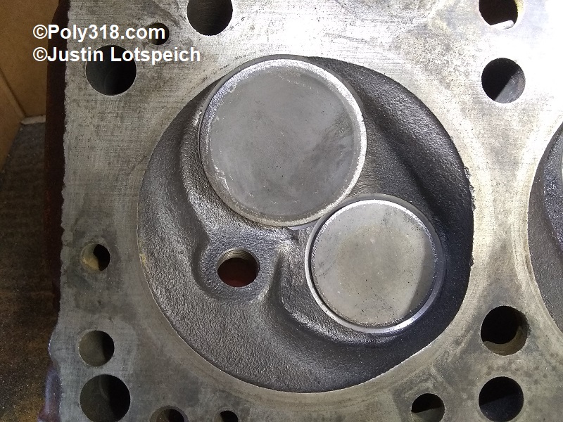
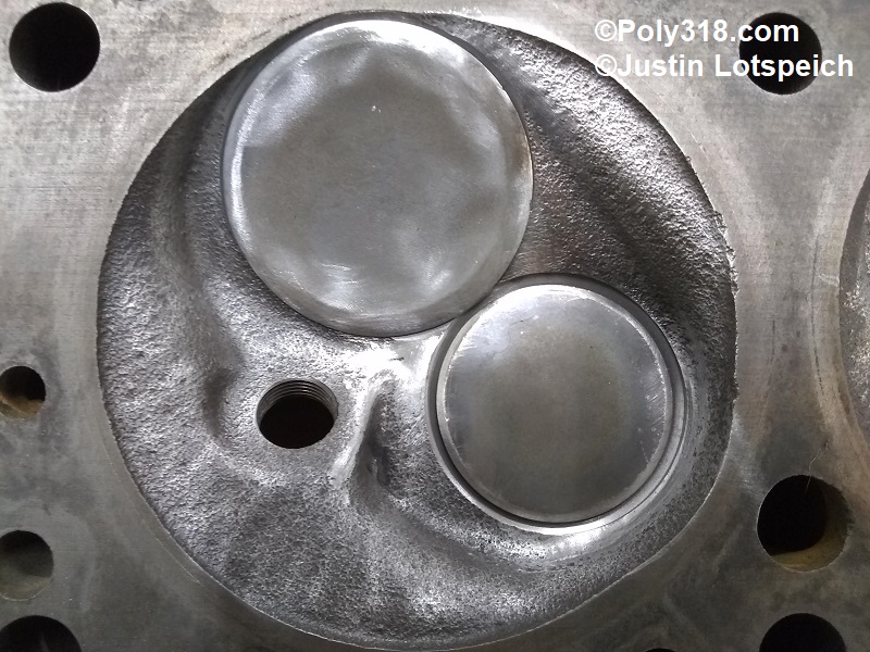
- Looking at the combustion chambers (Figure 20), note that the end chambers have casting “arrows” between the seats that I knock down with the ball carbide bit (Figure 21). After the larger valve seats are installed, I will go back in and finish easing any edges in the chamber.
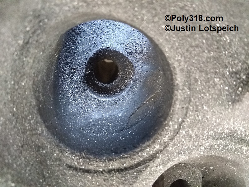
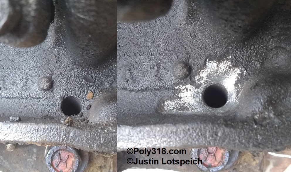
- As part of my oil system modifications (see my technical article), I chamfer the two drain holes to assist with oil drain-back (Figure 22).
Work after Valve and Guide Machine Work
While requiring more trips to my machinist, I have my machinist rough cut in the larger valves and then give back the heads for my blending before he finishes the valve job. If I accidentally hit the 45-degree seat cut while blending and sanding, there won’t be an issue since the valve job will remove any damage.
- The enlarged intake seat will cut down into the bowl leaving considerable ridges and a nasty cliff on the long turn (Figure 23). Using the ball and tapered carbide bits, I blend the new seat just below the 45 degree seat cut into the bowl being careful not to hit the 45-degree seat cut and then blend the bowl into the runner (Figure 24). Keep in mind that there are bulges in the runner walls at the mouth of the bowls for the pushrods, bolt holes, and water jackets (Figure 25). While I have seen these bulges removed for ultimate performance using a CNC program, it requires bushing the pushrod hole and epoxying the runner since removing the bulge will break through the wall. Rather than focusing on removing the bulge completely, I smooth the radius into the bowl and back into the runner for easier air flow; this method is good for 450 HP.
- For the intake short turn (Figure 26), I smooth the cliff back into the runner floor keeping in mind that this area is thick enough to allow for a more gradual ramp (Figure 3). I focus on not cutting the corners of the runner too much into the seat area since it is easy to undercut the seat here. When finished, the turn should be gradual and smooth (Figure 27).
- The exhaust bowls are the most work on the Poly 318 head after the hardened seats are installed. All bowls except the exhaust crossover will usually have both a large dimple and groove (Figure 28). Using the ball carbide bit, I smooth these areas working from the combustion chamber side. I then use the rounded-barrel bit from the exhaust port side to finish smoothing the dimple (Figure 29).
- The short turn will have a thick, sharp edge (Figure 30). Using the rounded-barrel bit, I radius the turn, blending into the walls while being careful to maintain a tapered wall going from smaller at the mouth to larger at the exhaust port (Figure 31).
- For the bowl with the exhaust crossover, the hardened seat often creates a ledge into the casting that needs blending using a ball bit (Figures 32 – 33). I blend the walls of the route to the runner and only knock down any casting flash I can reach in the exhaust crossover that would impede the flow. Because of the crossover design and that I plug the exhaust crossover in the intake manifold, there is going to be turbulence in this runner, so it isn’t necessary to worry about smoothing out the crossover portion.
- After all the carbide work in the intake and exhaust bowls and runners, I hit all the surfaces with 80-grit sanding barrels being careful not to get into the 45-degree seat cuts (Figures 34 – 35). Some people go even finer on the exhaust, but I don’t.
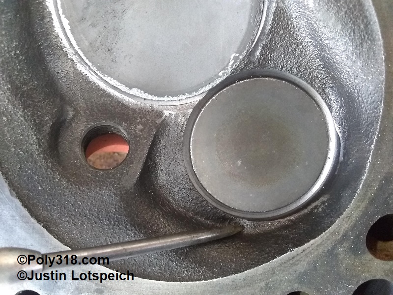
- Turning my attention to the combustion chamber, I drop in junk 2.02″ and 1.625″ valves to protect the seats (Figure 36). On multiple chambers, there is a hump at the exhaust seat (Figure 37) and around the seats that require smoothing. Working with fine cone stones in the die grinder, I remove the hump at the exhaust, between the seats, and the ridge around the seats. As the final touch, I hit the entire chamber with 120-grit abrasive pad balls (think Scotchbrite on a stick) in the die grinder to smooth my stone work and knock off any sharp casting ridges (Figure 38). My goal is not to polish the chamber but to eliminate any hot spots keeping in mind that any material removed increases the chamber volume and, thus, decreases compression ratio, which I don’t want.
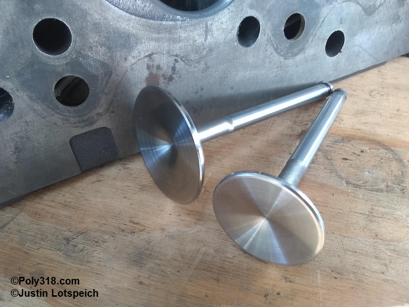
- Figures 39 – 40 show the finished chamber with the new 2.02″ and 1.625″ stainless steel race valves.
Acknowledgements
I want to thank Ray and Ben Bell for sharing with me photos of the A-block head they cut up into sections. Also, my thanks to Gary Pavlovich for chatting with me on the phone about porting and for sending me flow charts and a few reference photos of his porting work.
FIGURES