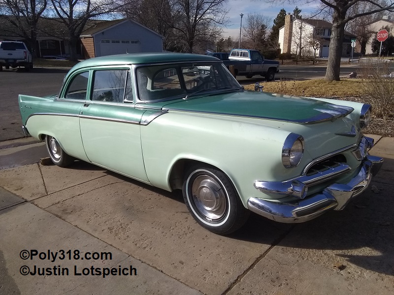
1956 Dodge Dakota
Front Suspension Clip Swap
(also applicable to Plymouth, Chrysler, and DeSoto)

Introduction
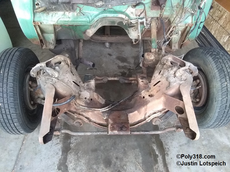
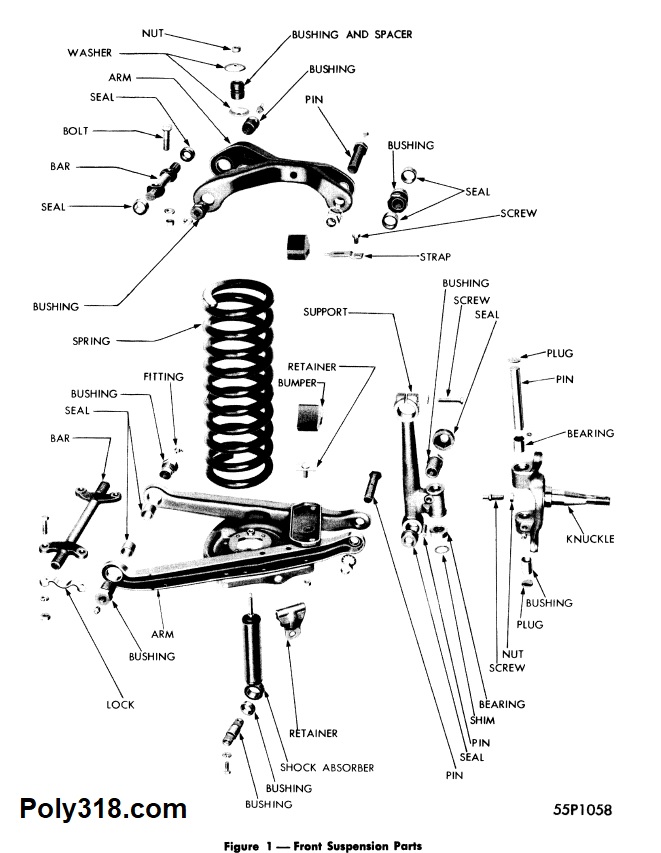
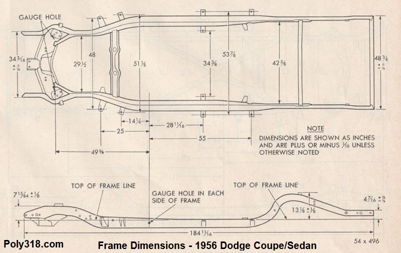
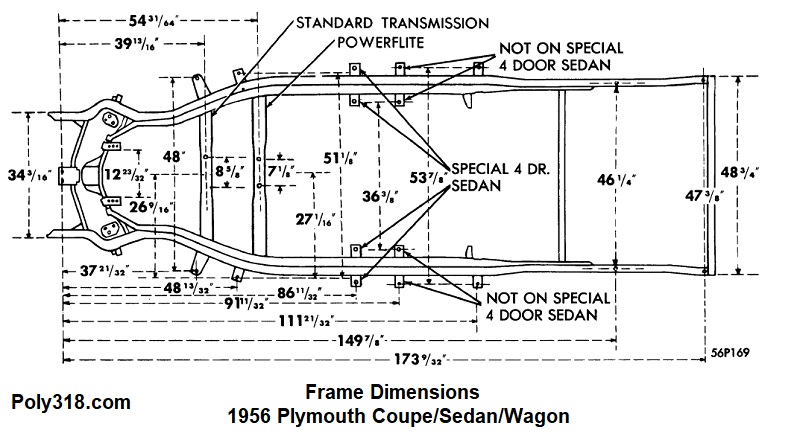
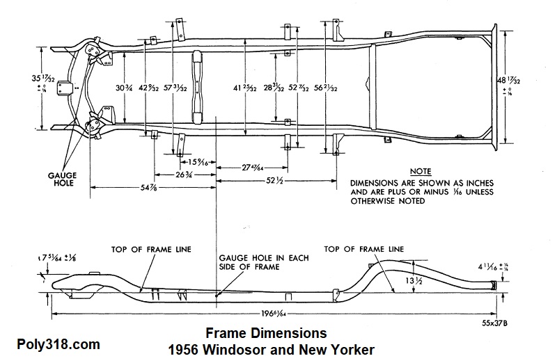
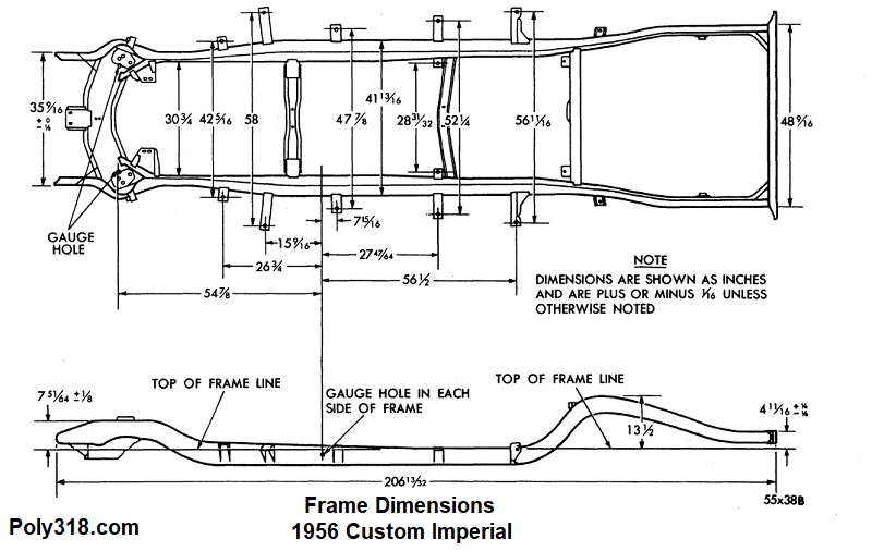
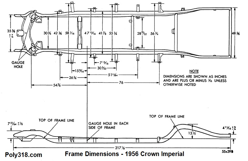
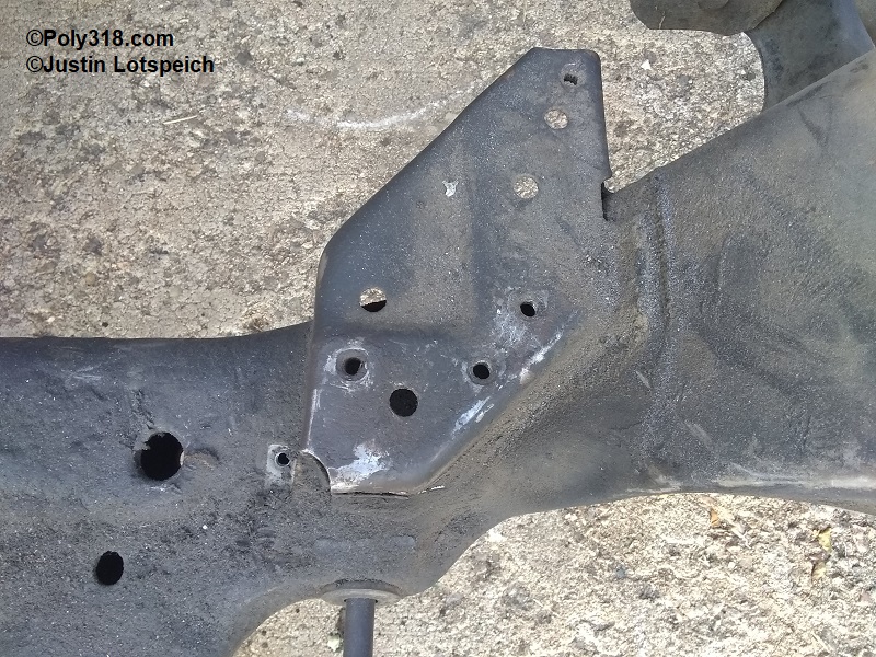
Our 1956 Dodge, like Plymouth, Chrysler, and DeSoto, came stock with independent front suspension that utilized a kingpin support rather than ball joints, skinny cast-iron upper control arms, a tiny sway bar, and wimpy drum brakes (Figures 1a). If I intended on floating around town for burgers, I’d simply rebuild the front suspension and stockpile parts for any necessary maintenance in the future, but going through the 1/4-mile traps above 100 mph with a screaming 450 HP Poly 390 stroker and blasting around corners up and down Rocky Mountain roads is a no-go for me with the stock suspension, steering, and brakes. While there was nothing inherently unsafe with new 1956 factory suspension in a stock car, Mopar finally abandoned the design in 1957 for good reason–late in the game years after GM and Ford had already moved on to ball-joints and beefier control arms. While Mopar certainly looked forward in many ways, not so in their 1955 – 1956 suspension despite what the purists say. The design dates back to the early 1940’s, the components now have over 65 years of stress and wear on them, and rebuild parts are getting more expensive and growing more likely to go out of production altogether with each passing year. Disc brake conversion kits are available through a couple small outfits, but they are expensive and maintain the inferior kingpin and control arm design. Stouter Chrysler and DeSoto parts can be made to swap into Dodge and Plymouth cars but suffer from the same kingpin and steering shortcomings. Figures 1b – 1f look at the different frame dimensions for possible front clip donors. While I don’t have a scans from a 1956 DeSoto manual, I believe the front suspensions are similar to the Chrysler scans provided below.
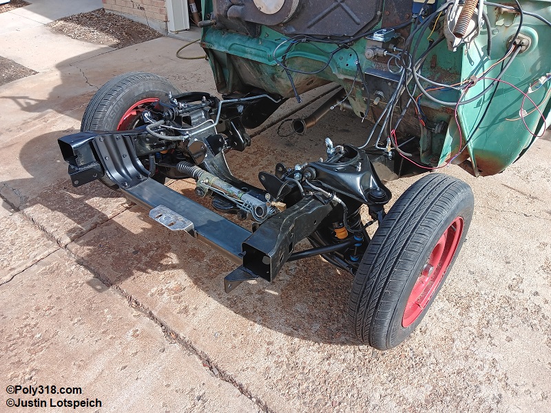
Now that I have the car back on the road after I rebuilt the engine and transmission and swapped and rebuilt the front and rear suspension, I can attest first hand that the Dakota clip is a gigantic improvement over the factory suspension. With the Dakota clip and sway bar, new 8-leaf rear springs I had custom built to correct the factory rear geometry, and the power steering pump I used, the car steers, rides, and handles amazingly turning at low speeds in parking lots, cruising around town, and at speed in the curves. The ride is smooth, the steering is tight and responsive, the steering wheel has good road feel, and the car stays planted in turns at speed without excessive lean. The car feels much more like driving an A Body than a boat. The Dakota disc brakes coupled with the disc brakes I have in the back using a manual master cylinder stop the car extremely well without excessive force on the pedal. I couldn’t be happier with the clip swap aside from not being able to match the length of the #1 header tube to the others out of the need to avoid the intermediate shaft, which I discuss in that section below.
Suspension Options
I went back and forth on different options from clipping the chassis with a late-1960’s Mopar torsion-bar setup to installing a Mustang II setup. I’ve clipped chassis and have installed Mustang II suspension before and know I could make either work. I also know how to beef up the weakest link in the Mustang II suspension–the lower tubular control arm pivot bolt boss–to where I’d be comfortable running it on the car.
I came across a 1950’s Dodge truck enthusiast forum where people discussed running a first-generation 1987 – 1996 Dodge Dakota clip with good results and then found other resources discussing using the Dakota clip on 1955 – 1956 Plymouths. After researching parts availability, design, and speaking with two people who had clipped their 1955 Plymouths with Dakotas, I decided the Dakota clip was the way to go for multiple reasons. The first-generation Dakota utilizes a very stout, practical independent suspension design that includes 11″ disc brakes, rack and pinion power steering (manual racks are available), heavy 1.10″ sway bar, and 1/8″ thick plate steel chassis overlapped and continuously welded. The chassis at the splice location measures 28″ from inside rail to inside rail, close to the Dodge/Plymouth 29-1/2″. 2″ dropped coil springs and forged 2″ dropped spindles are also available if height adjustment is desired, as are airbag setups for the lowriders among us. 1987 – 1990 had 5-on-4-1/2″ bolt pattern rotors while 1991 – 1996 used 6-lug rotors, but the earlier 5-lug rotors will fit on the later spindles. Keep in mind with the rotor change came caliper changes, so the calipers and brackets must match the year of the spindle. Donor trucks are plentiful in my local salvage yards, and rebuild parts are cheap and easily available at any parts house compared to 1956 parts. Importantly for the 1956 Dodge, the Dakota track width and chassis width and height are very similar. The 1956 has a track width of 58-1/2″ and the Dakota 61″, so the additional 1-1/4″ width on each side will clear the fenders and does not look odd. I can run skinnier wheels or more negative offset to address the track width as well if necessary. The frame rails almost align perfectly to where the 1956 rails and Dakota rails weave together for a fit that visually is difficult to notice once everything is installed in the engine compartment.
From a financial standpoint, the Dakota clip is a no-brainer. While prices will vary by region and through the years, I spent $210 on the entire front clip and another $500 in premium parts to rebuild everything except the steering rack, which was usable for a total of $710 for the setup. In comparison, my price list for rebuilding the 1956 suspension and installing a disc brake conversion kit came to between $2,500 – $3,000–assuming I don’t need to find any used hard parts if mine are wasted beyond machining, and quality wide-track Mustang II kits run about $3,000 with a manual rack.
Parts List for the Donor Clip
Used Parts from the Salvage Yard
- Chassis clip
- Upper and lower control arms and hardware
- Coil springs and rubber cushions(unless using aftermarket)
- Spindles, bearing nuts, bearing washers, bearing cotter nut cover, dust covers (unless using aftermarket 2″ dropped)
- Steering arms and hardware (unless using 1990 – 1996 dropped spindles)
- Spindle caliper brackets and hardware
- Shock absorbers and hardware (unless using new)
- Rotors, wheel bearings, hardware (unless using new)
- Calipers and mounting hardware (unless using new)
- Caliper brake hoses and clips (unless using new)
- Hard brake lines up to the chassis master cylinder tee fitting
- Rack and pinion unit and input shaft rubber cap for use or rebuild core
- Sway bar and mounting u-clamps
- Sway bar links (unless using new)
New Parts for Rebuilding the Clip and Modifying the Steering
- Upper and lower control arm bushings
- Upper and lower ball joints
- Upper and lower bump stops
- Shocks
- Rotors (if worn beyond tolerance)
- Wheel bearings, races, and seals
- Calipers (if suspect/leaking)
- Brake pads
- Brake hoses
- Sway bar link bushings
- Tie rod ends
- Steering shaft (for the column)
Pulling the Clip
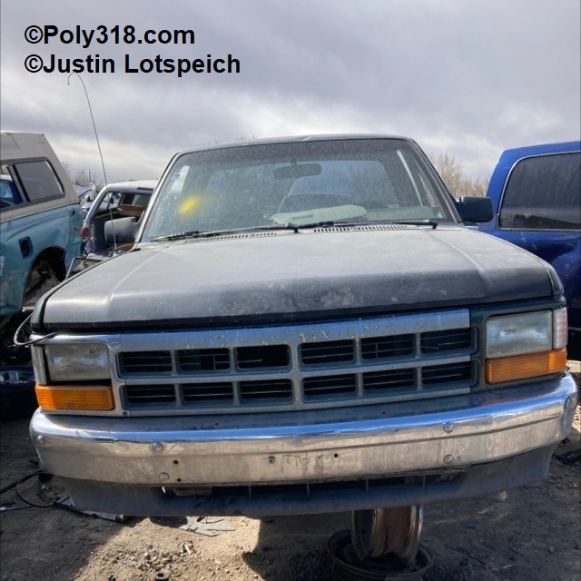
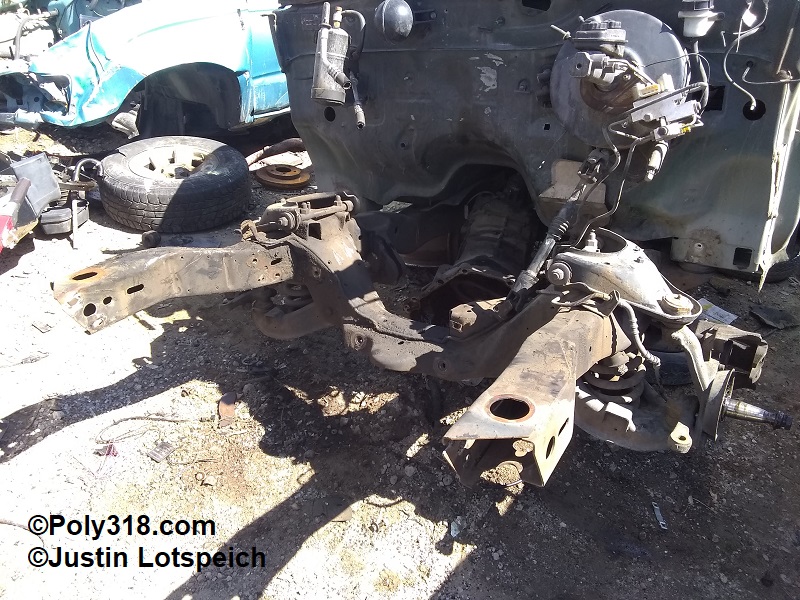
At a local salvage yard, I found a 1996 Dakota and went over on a Saturday afternoon to prep it (Figure 2a – 2b). To my appreciation, someone had already pulled the engine and in the process butchered the A/C hoses and some of the wiring making my life much easier since I wouldn’t need to disconnect and prop up the engine and remove the A/C and electrical harness since I don’t butcher good parts to get to the ones I want. After a close inspection of the chassis and components for damage, I pulled the bumper, the front sheet metal as one unit, and master cylinder brake lines. I removed the 6-lug rotors and calipers so as to not be charged for them since I wouldn’t use them. I removed the front cab chassis mounts, lifted the body, and jammed the rotors between the cab and chassis to give the Sawzall blade clearance room to cut from the top down. The donor truck never came with a sway bar, but I took one and the mounting brackets off a 1994 Dakota a few rows down. I left the truck as the yard closed that evening.
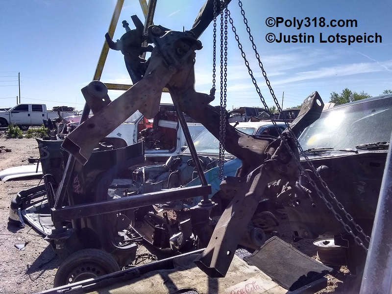
The following morning, I checked the yard’s inventory again before leaving home and was pleasantly surprised to see that they just inventoried a 1989 Dakota. Along with my uncle for a second pair of hands, I headed over with a gas generator, Sawzall, and grinder with blades and cut-off wheels. We visited the 1989 Dakota to find it had been wrecked in the rear and had brand new 5-lug rotors, National bearings, and what looked like a cleaner steering rack, so we snagged those parts. Back at the 1996 Dakota, we lifted the front end to reposition the jack stands underneath the cab. I cut off the frame 9″ back from the back of the body mount bracket, which leaves plenty of extra material for layout of the clip splice. We hoisted the clip onto a wagon and made our way to checkout (Figure 2c). $210 later, we had everything loaded in my truck and headed home.
1956 Chassis Prep
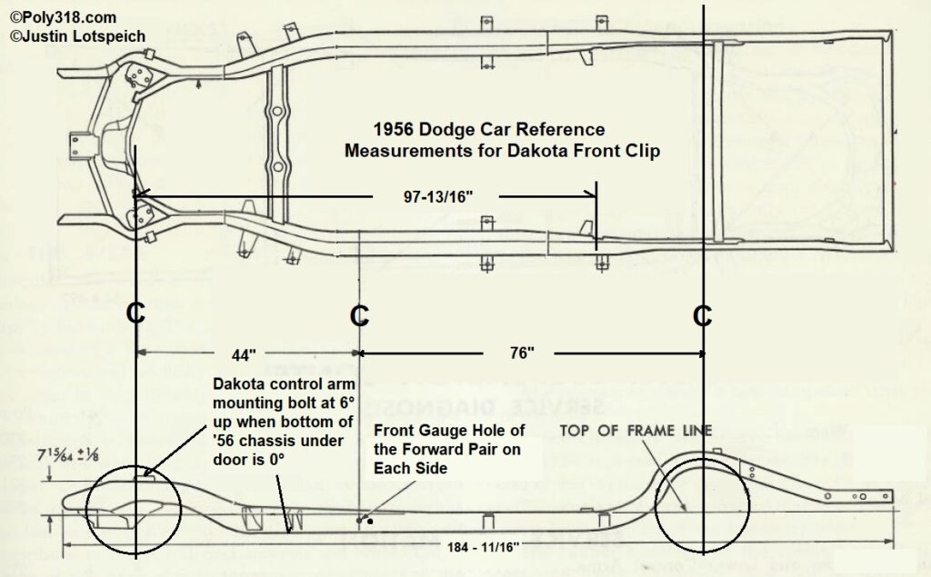
Before removing any components, I took baseline measurements of the wheelbase and began recording them on paper (Figure 3a). Using a three-way laser level on the concrete floor, I shot up to the front of the rear axle housing, measured back 1-1/2″ (half the axle diameter), and marked a line on the floor as my center of rear axle. I marked the floor at the center of the front kingpin and pulled a tape measure from the rear to the front mark. In the case of my car, I measured 120-5/16″ left and 120-1/8″ right, so something was out of square, which isn’t abnormal on a car this old with 97,000 miles and worn out rear leafsprings and bushings. But was the issue the front or rear? My educated guess was the rear, and to confirm I located the pair of measuring gauge holes on the side of the frame rails under the front doors and used a square to draw a plumb line through the center of the forward-most hole. I will refer to this gauge line as the “frame gauge.” I shot the laser up to this line, marked the floor, and pulled a measurement from the frame gauge to the kingpin mark for “44 on both sides, suggesting the rear end was out of square. To confirm this front measurement, I lasered up to the front of the body mounting bracket just forward the front leafspring perch and pulled a measurement to the kingpin mark for 97-13/16 on both sides; I now had two measurements confirming the front axle centerline was square with the chassis. I pulled a measurement from the rear axle centerline to the frame gauge mark and found 76-5/16″ on the left and 76-1/8″ on the right, matching my initial wheelbase measurements (76-5/16″ + 44″ = 120-5/16″ right and 76-1/8″ + 44 = 120-1/8″ left) and confirming the rear end was out of square. From here on, I would rely on the two chassis points (frame gauge and body mount at the front leafspring perch) for my front clip and would use these same points when eventually installing the new leaf springs and Ford 8.8” rear end to ensure the front and rear suspension were square to the chassis and each other.
The last two measurements I took were from floor to bottom of rocker panel at the front (10-1/2″) and rear (10″), keeping in mind the leafsprings are badly sagged/flattened.
Having my baseline measurements, I prepped the front end. I won’t go into great detail on this process since anyone capable of this clip swap will be able to figure out how to dismantle the items, so here is a list of main procedures.
- Indexed and disconnected wiring harness/components and pinned main loom up under a wiper blade
- Drained radiator,removed engine and heater hoses, removed radiator
- Removed hood (left hinges on cowl)
- Removed bumper brackets from the chassis keeping the bumper attached to brackets
- Removed fenders/inner fenders/radiator support/grille as one unit
- Drained PowerFlite transmission by removing the filler neck (oil will poor out the shifter cable hole if not drained)
- Removed engine, transmission, driveshaft
- Removed steering box and pulled column into the cab
- Disconnected brake line and cut it off at the cowl (I am running new lines and didn’t care about saving this line)
- IMPORTANT: compressing the gas tank with air, I drained the fuel tank into a can until no more fuel came out of the line. I then hack-sawed the fuel line off in front of the cowl and bent it back alongside the frame rail to the rear tire far away from the cutting/welding area. Out of extreme precaution, I plugged the end of the hose with a rubber vacuum plug. I am running a new 3/8″ line and didn’t care about saving this line. If the line needs to be saved, disconnect it at the coupling under the door and cap it with a fitting.
- Cut exhaust head pipes back out of the way (I am replacing the exhaust and didn’t care about saving it)
- If removed, reinstall the transmission crossmember
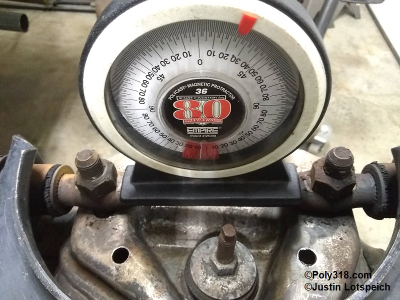
I placed the car on jackstands under the rear axle tube and under the frame rail below the front door hinges. With the laser level on a stationary object a few inches off the concrete, I shot in the front of the chassis under the front door hinges and the rear of the chassis near the front of the leafsprings and used pieces of metal flatbar and sheet metal to shim between the chassis and jackstands until the chassis was level side to side and back to front. I placed the protractor on the bottom of the frame rail parallel to the frame under the door and confirmed 0°. Note: do not take angle measurements off the top of the ’56 frame rails between the cowl and control arms because the chassis inclines.
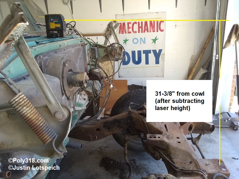
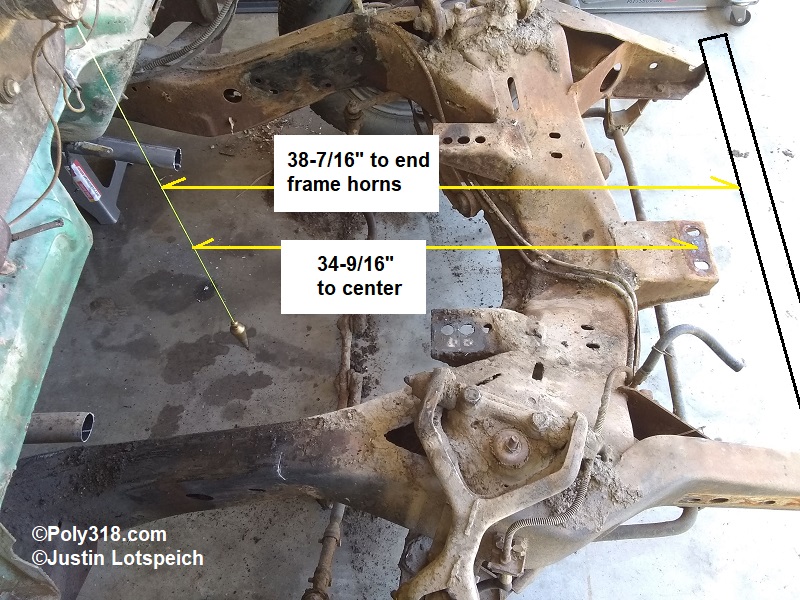
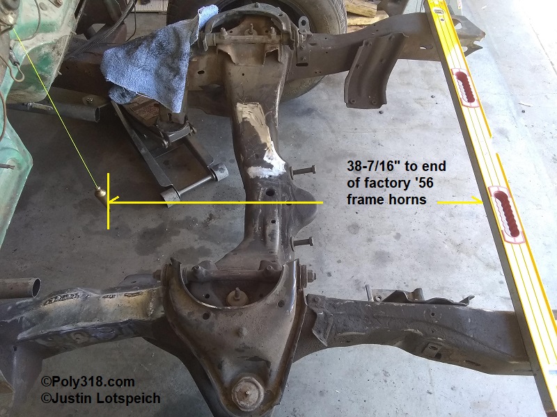
For the radiator core support bracket and frame horn placement, with the laser level placed at the center of the closed cowl vent, I shot forward and measured from the top of the radiator core support chassis bracket for 31-3/8″ after subtracting the laser level body height (Figure 3b). I dropped a plumb bob from the center of the cowl down the firewall lip and measured from the plumb line to center of the radiator core support chassis mounting holes for 34-9/16″. I also placed a 4″ level across the frame horns and measured from the plumb line for 38-7/16″ (Figure 3c).
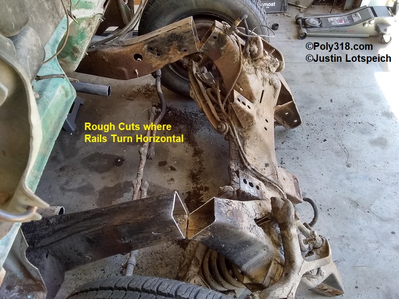
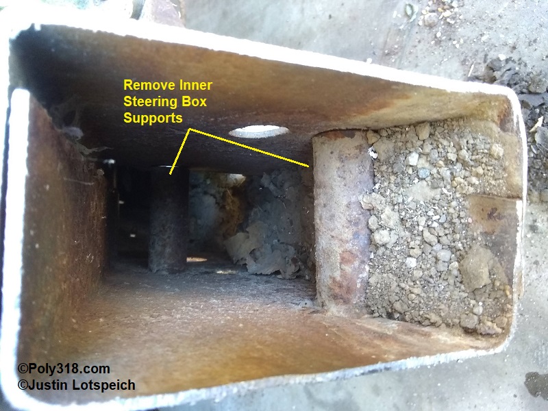
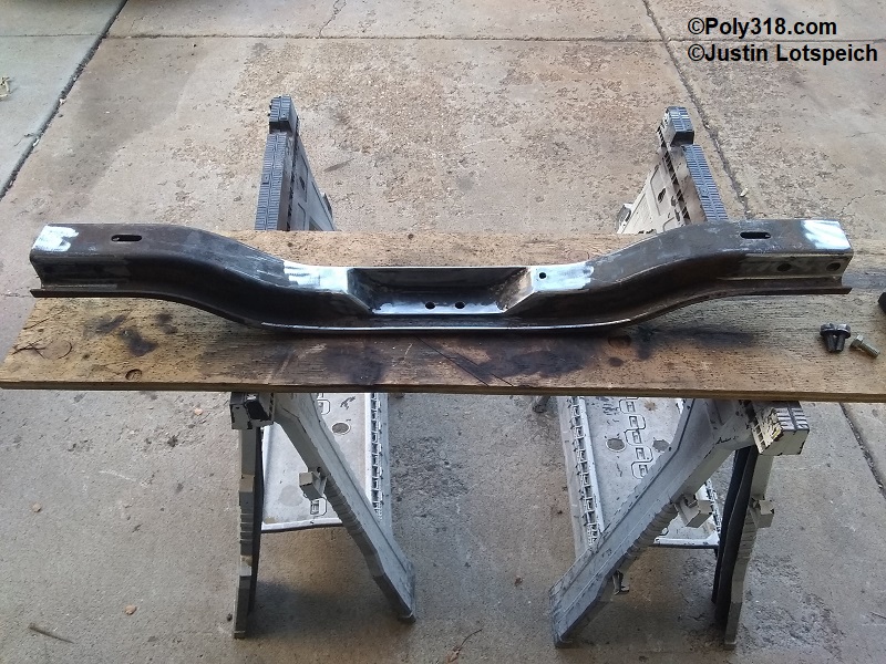
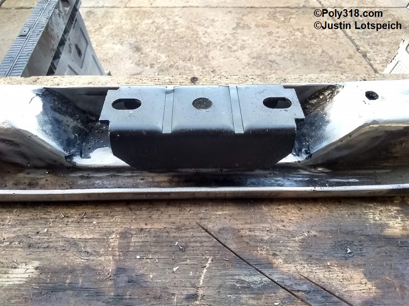
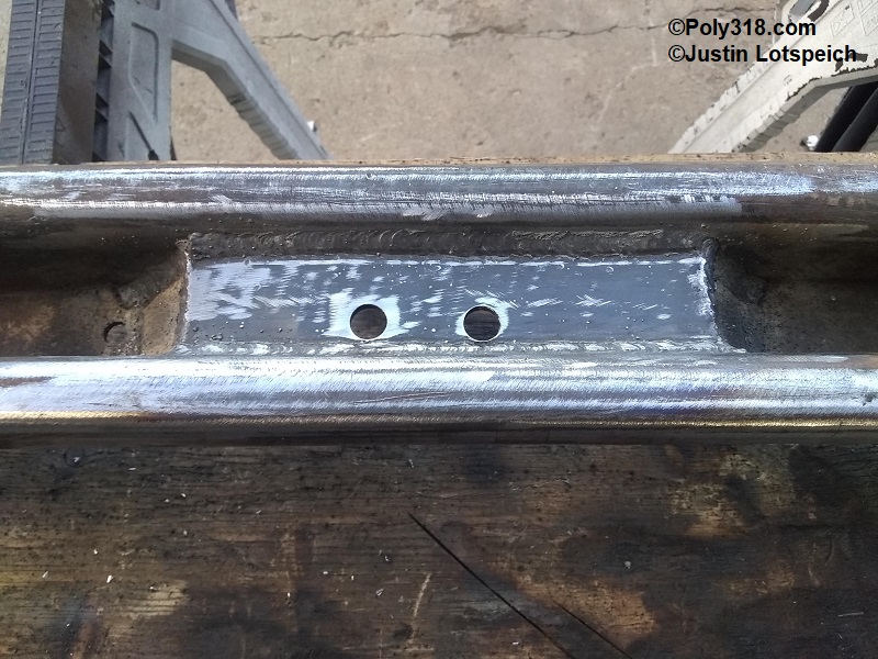
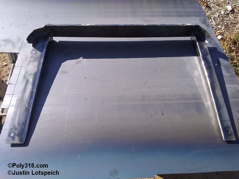
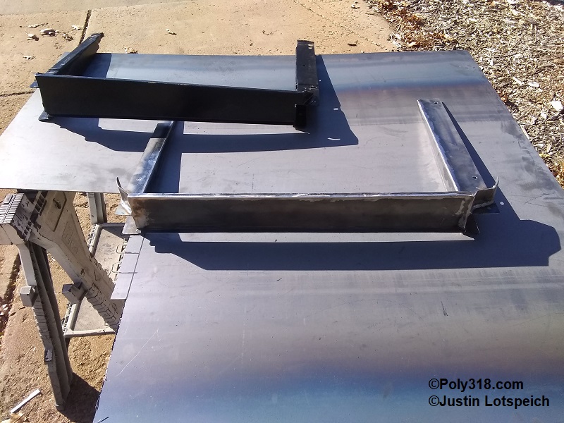
I used a Sawzall to cut off the clip where it turns horizontal after the angle up and begin flaring for the spring well to allow plenty of material to play with during layout and trimming and removed the clip with a cherry picker hoist (Figure 3d). I cut out the two steering box crush sleeves in the left rail so the Dakota outer rail will slide in, which I explain later (Figure 3e). In the case of my car, which came out of dirt-road Kansas, the frame rails from the cut back through the door had 2″ deep of gravel/dirt/mice nests/mud-wasp nests. Using a long rod, mallet, shop vac extensions, and compressed air, I vacuumed and blew out as much as possible, which ended up literally filling half of a 5-gallon bucket. At a later date when I have the body off the chassis, I will raise the back and wash out the rails well with water since I couldn’t get everything out.
Dakota Clip Layout
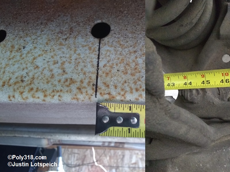
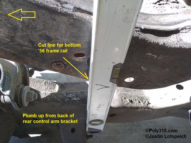
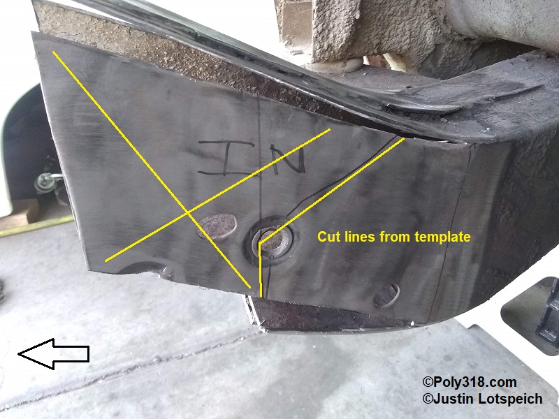
I relocated my floor chassis measurement points since placing the car on jackstands moved them. I shot and marked laser plumb lines onto the ground at the frame gauge, body mount at the front leaf spring perch, and center of rear axle. I slid the Dakota clip onto the floor underneath the ’56 rails and slid it back until I measured 44″ (refer back to Figure 3a) from the frame gauge mark to center of lower ball joint (Figure 4a), which is center of spindle. I shimmed the clip with wood blocks and used a Snap-On WA40 caster-camber gauge to roughly pinpoint the needed angle of the Dakota upper control arm mounting bolt. Through trial and error, I narrowed the angle to 5° up in the front. Rechecking the 44″ measurement, I was ready to layout cut lines on both the ’56 and Dakota rails. Note: for the following figures, I place an arrow that points forward to assist with orienting viewers. I refer to non-cut layout lines as “plumb lines” or “level lines” and cuts as “cut lines,” and I have highlighted lines for better clarity where my scribe marks didn’t show up well in photos.
Analyzing the clip, I decided the strongest and, coincidentally, cleanest joint would “weave” the two frame sections. The ’56 top, bottom, and outer rails would envelop the Dakota rail while the ’56 inner rail would weave into the Dakota rail. Using this design, I could stagger all the lap joints and get a 7″ overlap on the outside, 4″ overlap on the inside, 9″ overlap on the top, and the bottom ’56 rail would butt into the Dakota lower control arm bracket where I could get a solid fillet weld. Where factory holes did not exist in the side rails, I would drill holes for Rosette welds. While ideally 45° vertical joints would be stronger since they are longer than a 90° joint weld, the angle cut to the rails would decrease overlap material in this case, so I opted for approximate 90° vertical lap joints. I walk through the figures here in a list, although the order is not important:
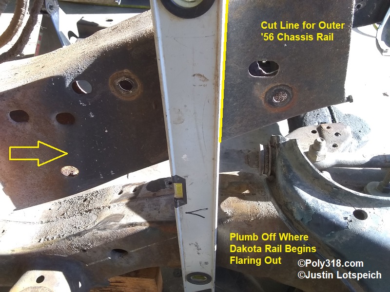
- Plumb up on the outer Dakota rail where it begins flaring out for the coil-spring well and mark the cut line on the ’56 outer rail (Figure 4b).
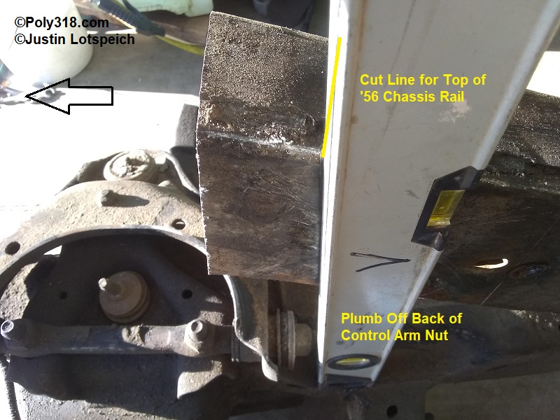
- Plumb up on the inner Dakota rail from the back of the control arm nut and mark the cut line for the ’56 top rail (Figure 4c).
- Plumb up from the Dakota rear of the rear control arm bracket and mark the cut line for the ’56 bottom rail (Figure 4d).
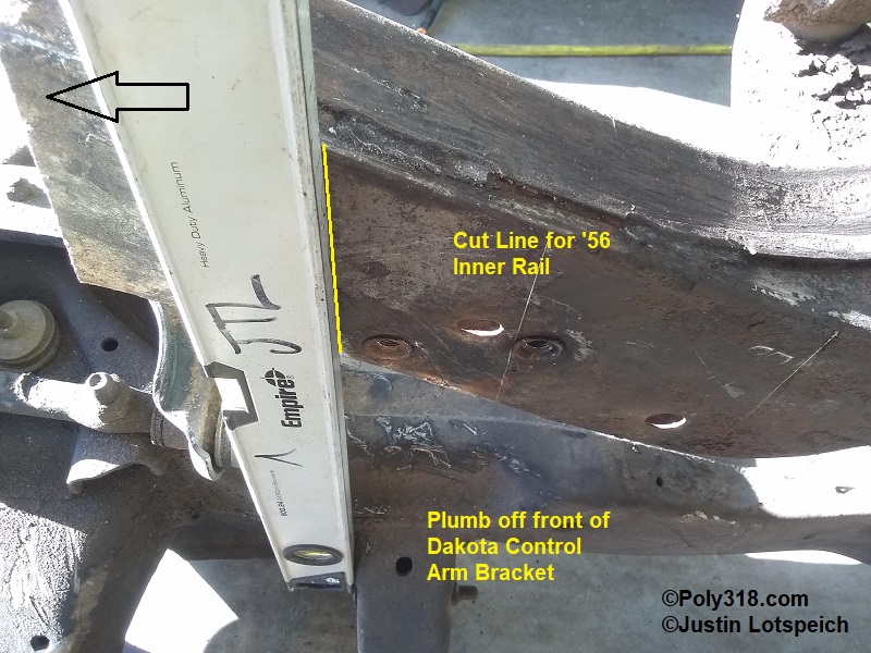
- Plumb up from the Dakota front of the rear control arm bracket and mark the cut line for the ’56 inner rail (Figure 4e).
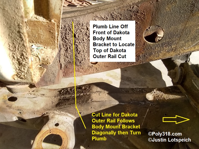
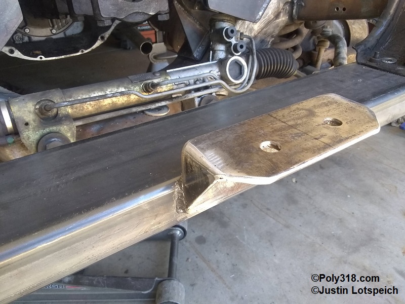
- Plumb up from the Dakota front of the body mount and mark a reference line on the ’56 outer rail and a small vertical cut line on the Dakota outer rail; mark a diagonal cut line on the Dakota outer rail that follows the body mounting bracket (Figure 4f).
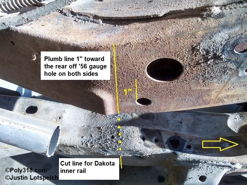
- Measure 1″ back from the small ’56 frame gauge hole near where the frame begins inclining. Plumb down from this 1″ mark and mark the ’56 rail for reference and the Dakota inner rail for the cut line (Figure 4g).
- Using a straight-edge, scribe the top and bottom of the Dakota rails to connect the inner and outer marks.
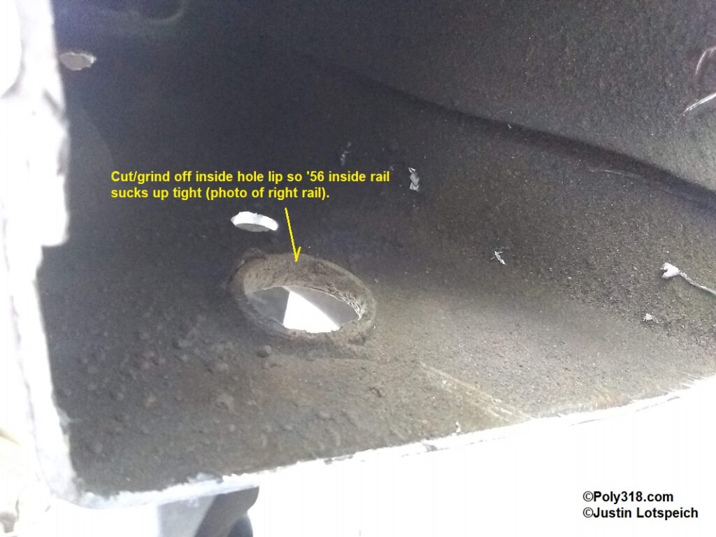
I pulled out the Dakota clip and used a cut-off wheel to cut both ’56 and Dakota rails and cut the four corner slits in the ’56 rails back to within an inch of the reference marks. I left these slits short in order to fine tune them during fitment so that I didn’t over-cut and have excessive welding gaps. Using a 40-grit sanding disc on my grinder, I cleaned off all offending corrosion/paint/grease where welds would land. On the inside wall of the Dakota left insider rail, I cut off the lip around the punched hole so that the ’56 rail would suck up tightly (Figure 4h). I did not bother with the lip on the right rail because I would cut it out at a later point I discuss shortly.
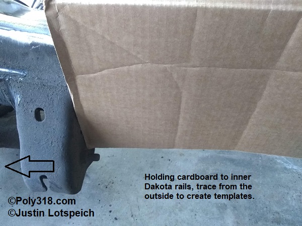
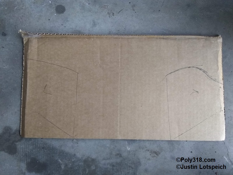
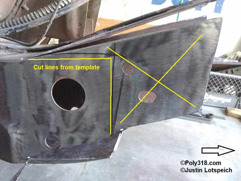
Using a piece of cardboard held to the inner Dakota rails against the rear control arm bracket, I traced the rail and cut out patterns approximately 1/4″ inside the lines for material clearance (Figures 4i and 4j). Placing each pattern onto its corresponding ’56 inner rail, I marked the outline, extended the horizontal cut lines, and marked vertical cut lines. I cut out these lines (Figures 4k and 4l). Where there were insufficient holes already in the ’56 outer rails and Dakota inner rails, I drilled 1/2″ diameter holes for Rosette welds. The top and bottom rails were skinny enough and get enough weld penetration that they did not require Rosette welds. To help with fitting the Dakota clip, I peeled the ’56 outside, top, and bottom rails out and pushed the inside rail in about 3/4″.
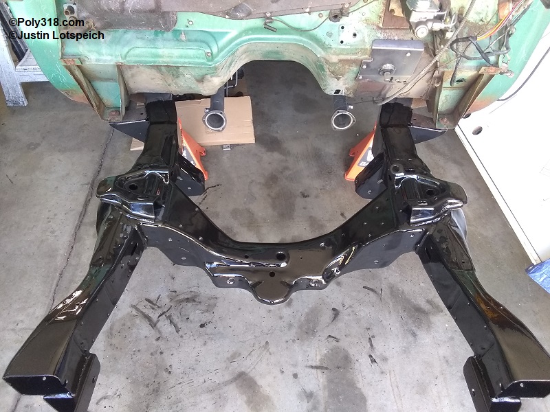
Dakota Clip Installation
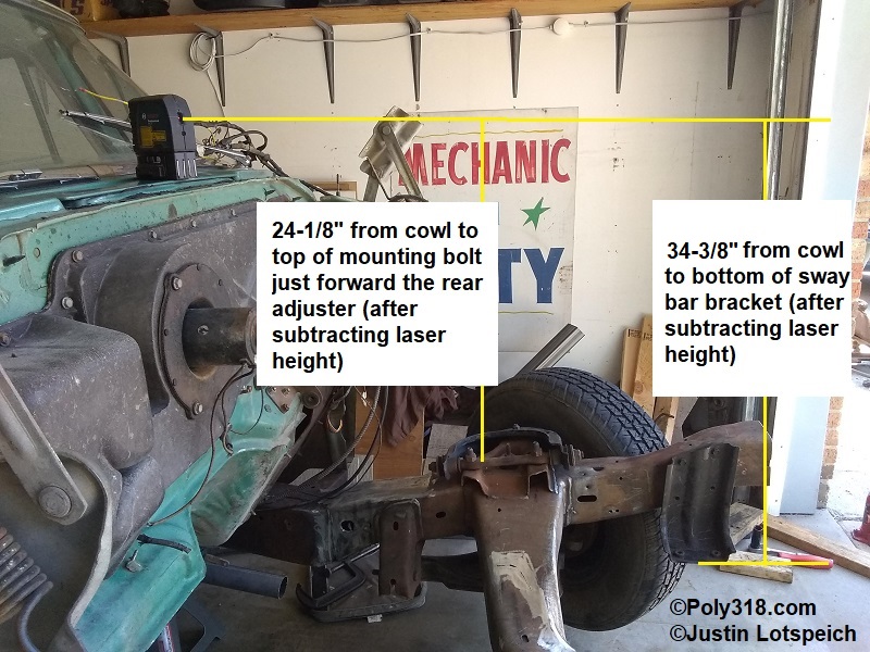
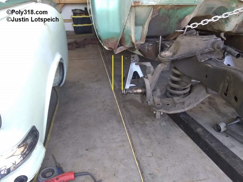
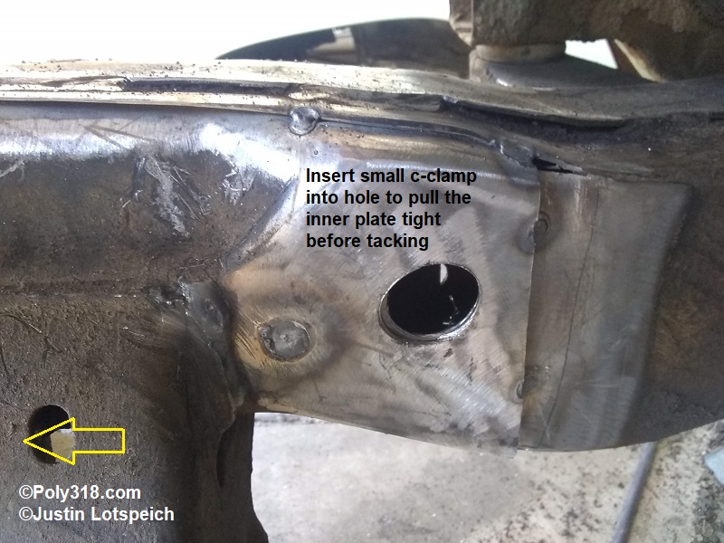
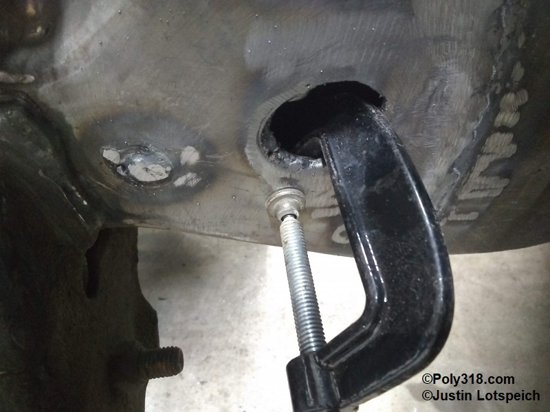
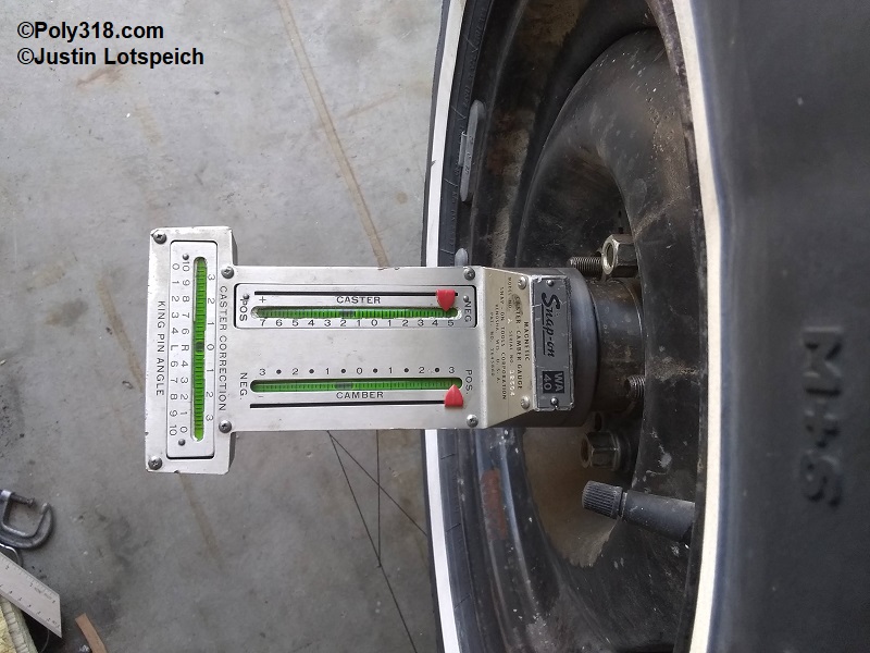
Using a cherry picker hoist, I lifted the Dakota clip into position and wiggled it into the ’56 rails, cutting the ’56 corner slits back and prying on the rails as needed until the ’56 bottom rails hit the Dakota lower control arm brackets. Now that the Dakota clip was in the air, I could pull a tape measure directly from the frame gauge line to the center of the lower ball joint to locate the needed 44″ adjusting the clip back/forward as needed. Once I obtained the 44″, I slide a small c-clamp into the hole on the left inside rail and sucked the ’56 inside frame rail tight against the Dakota inside rail. At this point, I rechecked the chassis angle placing the angle finder on the bottom of the ’56 rail below the door and confirmed 0°. I adjusted the control arm mounting bolt adjusters until both front and rear were centered in the slots. Placing the angle finder on the Dakota upper control arm mounting bolt, I adjusted the hoist until I reached 5° up in the front. With the wheels installed and the control arm adjuster bolts centered in the slots, I used the caster-camber gauge to check caster and found 1.25° positive, which was within the factory Dakota specs of 1.0° – 1.5° positive. However, I preferred to get the caster closer to 1.5° with the mounting bolt centered, so I placed a floor jack under the Dakota crossmember and raised the front of the clip to 6° up (Figure 5a). Rechecking caster found 1.625°. I placed the laser level on the center of the cowl vent and shot to the sway bar mounting brackets. Measuring up from the bottom of the bracket to the laser, I got 34-3/8″, lower than the factory radiator core support bracket, which I would handle with a raised bracket. I measured down from the laser level on the center cowl to the control arm mounting bolt just forward the rear adjuster and found 24-18″ on both sides, which became another baseline measurement (Figure 5b). Moving to the right inner rail, I used a 1-1/8″ diameter hole saw to enlarge the existing Dakota inside rail hole, removing its inside lip obstruction, and cut through the ’56 inside rail. I inserted another small c-clamp and secured the rails.
At this point, I triple-checked multiple measurements before tack welding, referring to my measurement sheet Figure 3a:
- 44″ from frame gauge under the door to center of lower ball joint.
- 97-13/16″ from front of body mount bracket near the front leaf spring perch to center of lower ball joint.
- 120″ from center of rear axle to center of lower ball joint. Note: as I mentioned earlier, my rear end was out of square, so with the two control measurements above spot on, I expected to see 120-5/16″ on the left and 120-1/8″ on the right since the rear end was out of square, which I did.
- Confirm the bottom ’56 frame rail under the door was 0°.
The final consideration is ensuring the clip is centered side to side. Visually, where I cut the Dakota rails and had them pushed up against the inside of the ’56 outer rails, things looked even. I build a two-post jig with posts of the exact same length that fastened to the rear wheel via the lug nuts that allowed me to secure a string line on the back post and use the front post for alignment. I set up a heavy moveable object at the front of the chassis to anchor the other end of the string line taut. With the help of someone watching the front post on the rear wheel jig, I pushed the heavy front anchor in toward the middle of the chassis until the string line hit the front jig post. This string line was now at 90° to the rear axle, and I shot and marked a laser plumb line onto the floor for future reference if needed. I measured from the string line to the tip of the spindle on one side of the car, set up the line on the other side of the car, and compared the two measurements (Figure 5c). In my case, one side was off 1/32″ and not enough to impact anything. If either had been longer than the other side more than 1/16″, I would have bent the split frame rails and knocked the clip toward the shorter side as needed until the measurements evened up.
Pondering the Ride Height
Before moving on to welding, I wanted to assess how ride height would be impacted with the Dakota clip. It was impossible for me to nail down the difference using measurements between the ’56 stock and the new clip due to all the variables of spring rates, weight, etc. Taking multiple measurements, I surmised that the new configuration would place ride height around the same as the factory baseline, although I would prefer a couple inches lower. 2″ dropped coil springs (Belltech 4761) and 2″ dropped spindles (Belltech 2605) are available, so I had room to adjust, along with any adjustment through tire size. The only way to get the ride height lower using the clip would be to “Z” the clip by raising it in the ’56 frame rail. However, this configuration requires substantial gusseting of the frame with 1/8″ plate to wrap the joints at least 6″ on all sides, it would move the engine higher in the compartment that might cause hood clearance issues, and it doesn’t look as clean/factory as the design I chose. For the lowriders out there, the Dakota clip can be safely Z’d into the ’56 chassis when properly lapping and gusseting it. I discuss the actual ride height at the end of this article that I measured after installing the engine, transmission, and front sheet metal, and I’ll have room to adjust with the springs and spindles if necessary later.
Welding the Dakota Clip
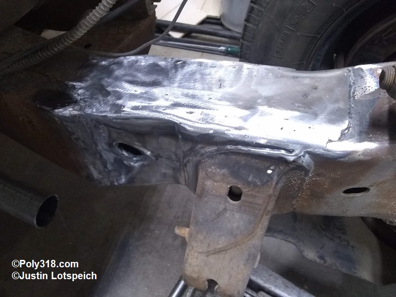
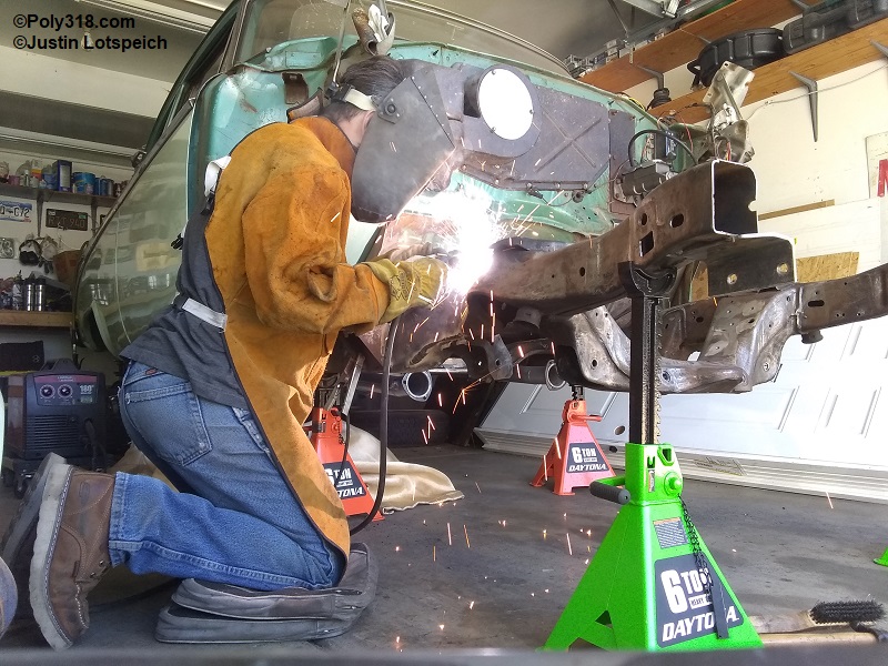
For this project, I used a 180-amp MIG with .035″ flux-core wire. Because I was welding on a 90° day, I did not have to consider preheating the metal; if I were welding in the winter/cold climate, I would preheat each joint to the recommended 50°F for 1/8″ – 1/4″ steel to assist with slower cooling of the heat affected zone. I double checked that all surfaces were clean and wiped them off with lacquer thinner. Starting at the top corner where the inner rails met, I placed a strong 1/4″ tack weld. With a small c-clamp through the inner rail hole to secure the inner rails, I pulled the outer ’56 rail tight against the outer Dakota rail using two large c-clamps and placed tack welds at the four top and bottom corners. I repeated this process on the other frame rail. At this point, I rechecked my control arm mounting bolt angle, 44″ from the frame gauge mark to the center of lower ball joint, and level across the frame rails. Satisfied with what I found, I clamped down the top and bottom rails and began tacking the joints and Rosettes closest to the cowl moving forward toward the control arms, clamping and using a hand sledge and ball-peen hammer as needed to ensure tight joints (Figures 6a – 6b). Once I tacked all joints, I did a final sweep with a wire brush and 40-grit sanding disc to clean up the tack flux and any areas I now knew I would be welding, and I used a pick to scrape out any debris from the original frame joint on the ’56 top rail that bubbled out when tack welding and peened that joint as tight as I could get it. I also peened where the corner slits in the ’56 rails ended to tighten those butt-joints.
Confident I had enough tack welds for the chassis to sustain the weight of the car, I lowered the car onto the tires and bounced the front and back a few times. Checking caster, I found the same 1.625° positive (Figure 6c). I wanted to verify the amount of adjustment available, so I loosened the two adjuster bolts and pried the rear bolt as far out away from the center of the car as possible and snugged the bolts with the front bolt still centered. Caster then read negative .25°. I moved the rear bolt as far in toward the center of the car as possible and rechecked caster at 1.75° positive. Ideally, I would have liked 2° on the upper adjustment, but the negative .25° – 1.75° positive would allow me to adjust into the Dakota spec of 1.0° – 1.5° positive. However, I expected the rear of the chassis to rise 1″ – 2″ after installing new leaf springs since the stock ones are badly sagged/flat, and this rise will decrease caster. To check, I jacked up the rear end 2″ and recheked caster to find 1.625° positive. Considering that raising the clip angle more than the current 7° would shift the adjustment range to 0° – 2° positive, it would also create radiator core support fitment issues since the sway bar brackets would raise the core support above factory spec. With all these variables, I concluded the clip was good where it was tacked and raised it back onto jackstands and rechecked the 44″ frame gauge measurement, frame rail angle under the door, and control arm mounting bolt angle.
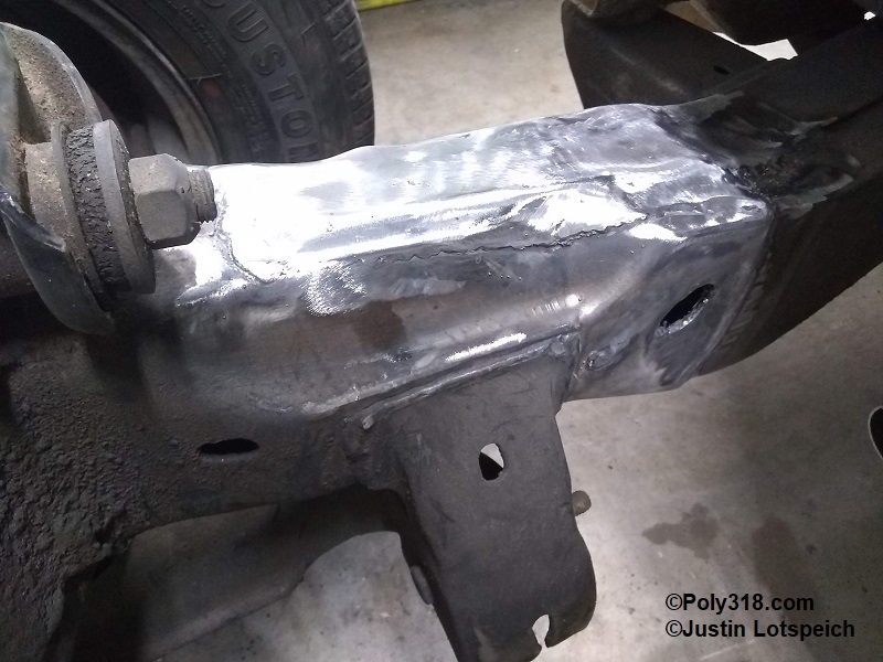
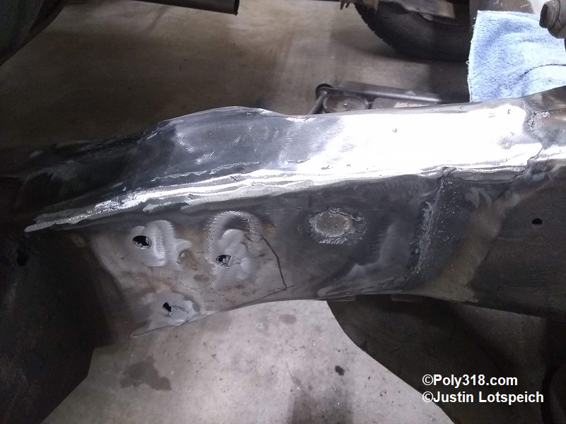
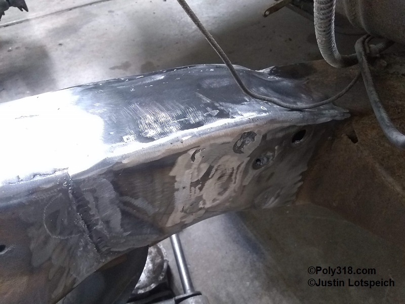
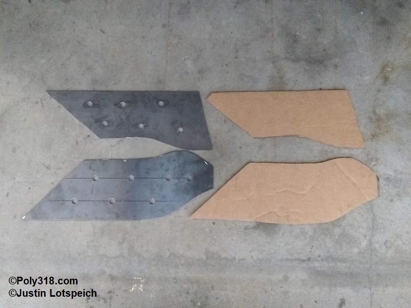
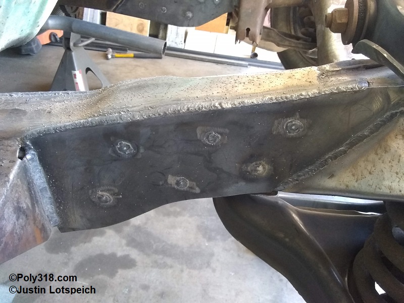
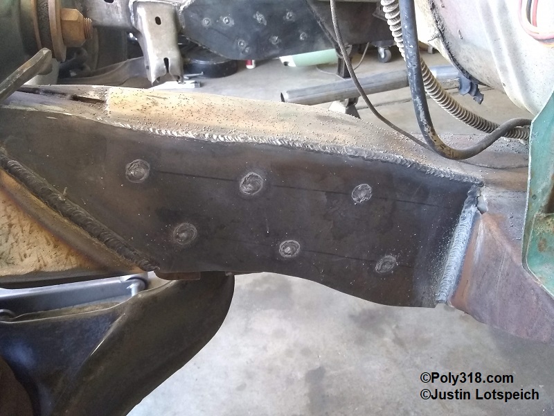
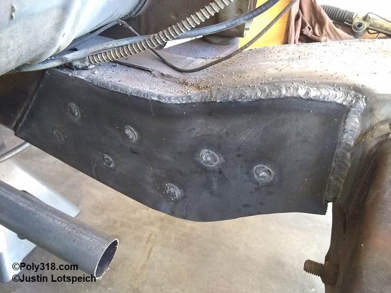
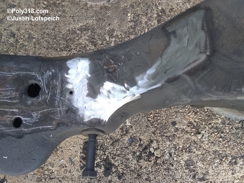
Ensuring I had light support under the Dakota crossmember from the floor jack, I welded all the Rosette welds. I then stitch-welded all the joints in 4″ segments at a time jumping from left inner to right outer, left outer to right inner allowing time in between returning to the same side for the steel to cool a bit to try and limit heat soak into the heat affected zone. The only joints I left tacked but unfinished were the bottom of the rails since I will be flipping the chassis upside down during paint prep and will weld them then versus welding them in the highly undesirable upside-down position. After letting the welds cool, I cleaned up everything I could reach with the 40-grit sanding disc on the angle grinder to give the final gussets an even mating surface (Figures 6d -6g). Using cardboard, I traced the outer and inner rails to make templates for the final gussets that serve as both structural reinforcement and aesthetic appeal to cover the lap joints (Figure 6h). I cut gussets out of 6″ wide 1/8″ plate and drilled a series of 1/2″ Rosette holes (Figure 6h). Using ample c-clamps to smoothly and tightly secure the gusset to the rails, I tack welded them in place, finished the Rosette welds, and welded in 4″ sections jumping around for cooling like the initial frame mating (Figures 6i – 6l). When I removed the suspension at a later point, I finished the welds I could not reach at this step. I welded the factory 1956 chassis top and bottom seams from the Dakota clip back to the firewall, and once I pull the chassis I will fully weld these seams all the way back. The factory chassis is skip-welded, which creates twisting known in these cars that is greatly removed by welding the seams continuously.
I pulled all the same measurements as before including the frame gauge to ball joint, frame mount near the leaf spring to ball joint, rear axle center to ball joint, control arm mounting bolt angle, and level angle across the frame horns and found everything the same with no sign of warping during welding.
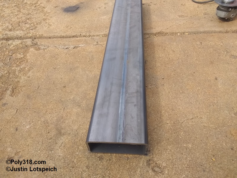
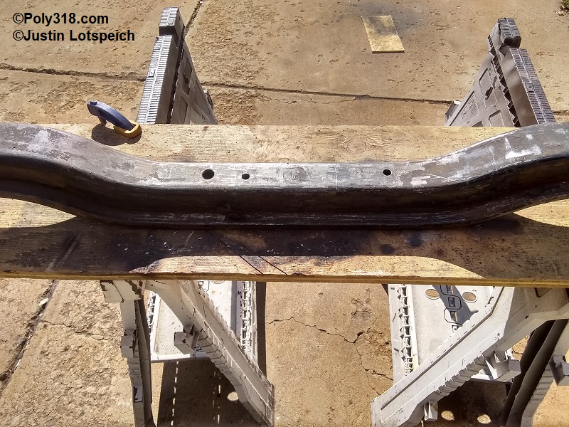
Radiator Core Support and Bumper Mounts
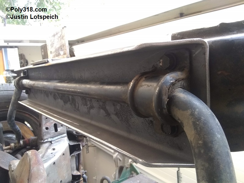
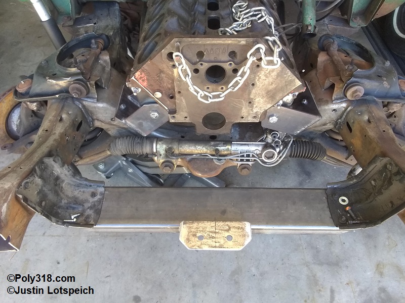
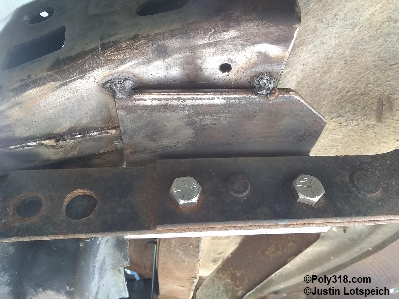
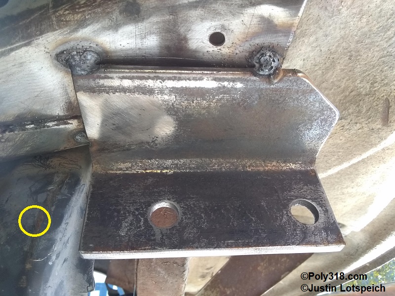
I dropped the plumb line off the center of the cowl again and measured out to locate the frame horn line. Using a 4′ level, I measured off the 44″ frame gauge control lines until the level was square with the rails at 38-7/17″ off the plumb line (Figure 7a). I scribed around the frame and cut them off with a cutoff wheel (Figure 7b). Focusing on the radiator core support crossmember, I sliced off with the cutoff wheel one side of a piece of 2″ x 5″ 3/16″ wall rectangular tubing, bobbed the corners at 45°, eased all the edges with a sanding disc, and drilled holes corresponding to the sway bar mounting holes (Figure 7c). For my build, the crossmember when bolted to the sway bar brackets is 34-3/8″ below top of the center cowl, 3″ below the factory ’56 core support mounting plate. I cut a piece of 3″ x 3″ x 1/4″ wall angle 7″ long, drilled the core support mounting stud holes 34-9/16″ away from the cowl plumb line, and clamped the bracket to where it rested 31-3/4″ below the cowl (the original 31-3/8″ plus a 3/8″ gap for a rubber spacer and room for shims for aligning the fenders and doors not originally used). I tack welded the bracket to the crossmember and finished welding it after I mocked up the sheet metal and confirmed the proper location and height (Figures 7d – 7f). For the bumper mounts, I used a 6″ long piece of 3″ x 3″ x 1/4″ angle profiled to match the bumper brackets. I hesitate to provide detailed measurement here because the hole positioning depends completely on the aesthetics of lining up the bumper, splash pan, and fenders to get all the reveals even. Figures 7g – 7h show how I built the mounts with two of the bracket holes in the angle and the back hole drilled through the Dakota sway bar bracket. For bumper alignment, it is important to have the fender-door gaps set, the radiator core support bolted in place on the sway bar crossmember, and the bumper centered.
Engine Mounts
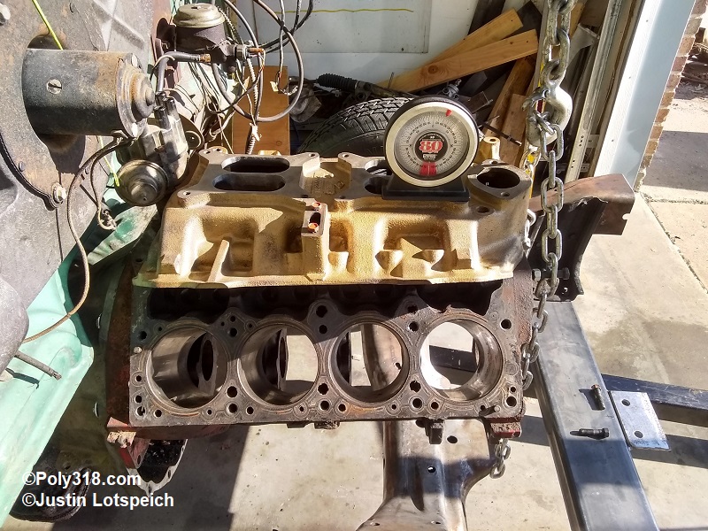
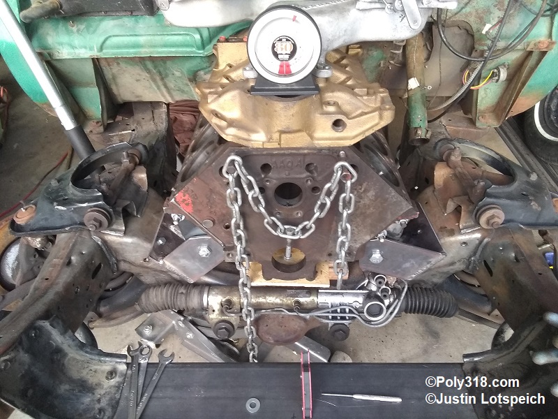
To prep the crossmember for the new A-block engine mounts, the factory left motor mount bracket needed to go, which a cutoff wheel and 40-grit sanding pad on the angle grinder resolved (Figures 8a and 8b). The engine should be installed level side to side and 3° down in the back for proper driveshaft pinion angle and to assist the cooling system with pushing any air pockets into the radiator. On A-blocks, the intake manifold’s carburetor flange is machined at an angle to where when it is level, the engine/transmission are at the proper 3° down in the back. Side-to-side angle is simply to shim, but front to back angle depends on many variables including the rake of the car when on the ground loaded (the difference in height of the rear of the rocker panel to the front of the rocker panel) and front wheel/tire size that will change this rake. For my build, I want an approximate 2″ rake with the rear higher than the front. To remove variables since I don’t have the front suspension loaded, I don’t have the new rear leaf springs installed, and I don’t have the new tires I will eventually run, I placed the chassis on jack stands with the 2″ rake shimmed in and the chassis level side to side. Mocking up a spare 1962 – 1965 TorqueFlite 727 and a bare A318 block, I placed the transmission tail shaft mounting flange directly atop the factory ’56 transmission crossmember and lifted the front of the block until I leveled the intake (Figure 8c). Playing with the engine height using the engine hoist and lowering or shimming the transmission crossmember to keep the intake level, I landed on the tail shaft mounting flange resting directly atop the crossmember without the transmission mount installed and the engine 17-7/8″ down from the center of cowl vent to the front lifter valley wall. This height allowed for 5-1/2″ oil pan clearance from pan rail to the closest rack obstruction, which will give 1/2″ clearance for the modified pan I’ll fabricate, better clearance for the rack and pinion u-joint, and hood clearance for my cross ram dual-quad intake setup. I shimmed the block main caps with wood blocks and removed the hoist. I installed a factory distributor for mock up and slid the engine/transmission forward until I had 3/4″ clearance between the distributor cap and firewall heater assembly cover for plug wires and engine movement. I’d like more, but my preliminary measurements suggested I can’t.
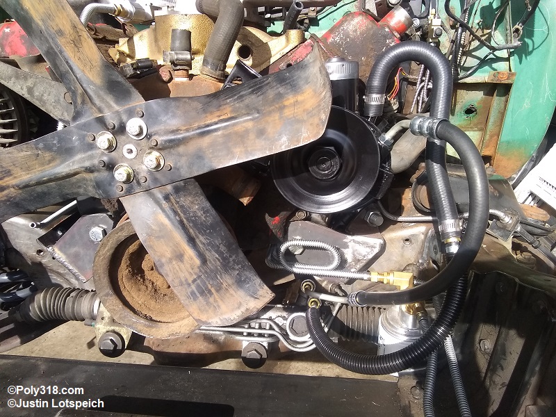
At this point, before moving forward with designing and fabricating engine mounts, I installed the front fenders/core support/grille assembly and radiator. I checked air-cleaner clearance (all good), inner fender clearance (clearancing is needed at the upper control arms), core support clearance to the Dakota frame rails (it rests nearly atop the frame rails), and cooling fan to radiator clearance. Mocking up a timing cover, pre-1970 iron/short/left-intake water pump, 2″ fan spacer, and factory fan that I intend on running for the aesthetics, I found almost no clearance between the fan and radiator. I installed a 1″ fan spacer that still allowed 1″ clearance between the fan and power steering pump pulley and was able to install the fan with 3/4″ clearance to the radiator. Tight, but usable. One area where I can obtain another 3/4″ clearance is to fabricate a new radiator mounting flange since the factory unit holds the radiator off the core support 1/2″ and at an angle to the engine since the factory ’56 Dodge/Plymouth engine was installed cocked in the chassis as Mopar experimented with pointing the transmission output shaft at the offset rear end pinion. Comfortable with all the clearances and the engine position, I removed the front sheet metal assembly.
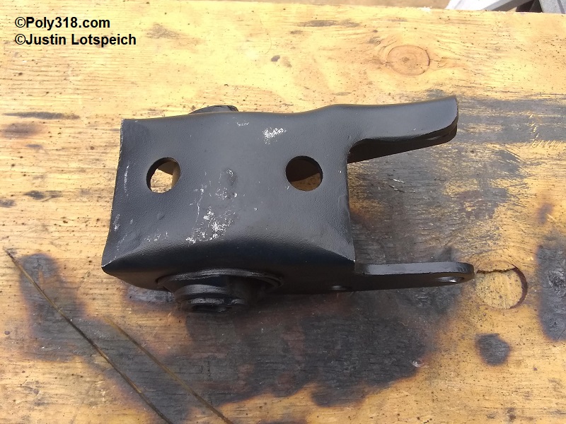
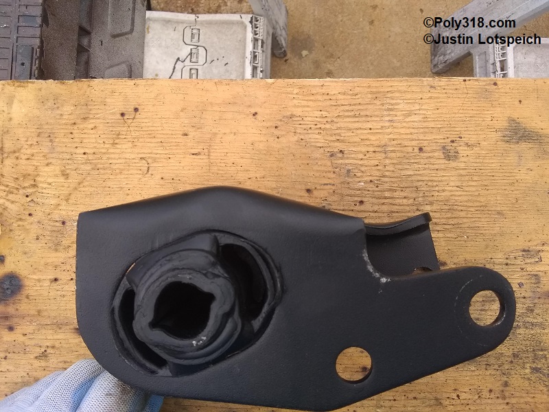
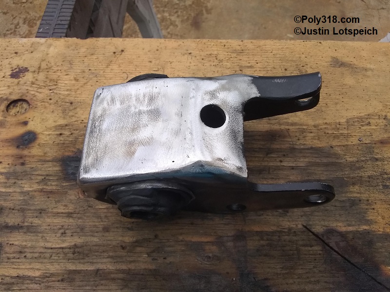
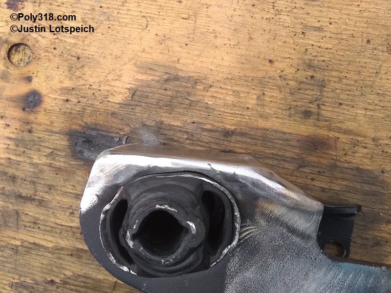
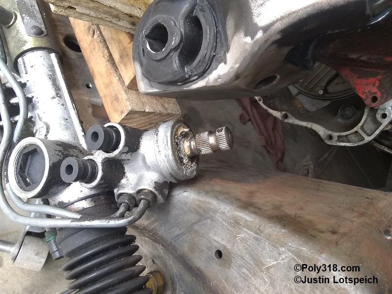
Turning attention to the steering, I installed the motor mounts. I wanted to use 1973+ LA captured motor mounts (2325 right, 2326 left) versus the un-captured pre-1973 mounts prone to splitting on high-performance setups. Installing the mounts to the block I immediately had clearance issues with the rack and pinion steering shaft. After much mock-up and brainstorming, I settled on modifying the mount bracket and then offsetting the engine to the right (passenger side) for additional clearance. A nice thing about the captured mounts is that the bracket is reusable, and inserts can be purchased separate to where I don’t need to worry about having to modify the bracket every time I need to change the mount–as if I will ever need to replace the mount. Using a cutoff wheel, I removed the large bulge in the bracket, cut out a flat piece of 1/4″ plate, and welded/ground the unit being sure to bevel the edges of the butt joints (Figure 8d – 8g). With the modified mount installed, I placed the engine 1/2″ off-center to the right to give the u-joint 1/4″ clearance for any engine movement (Figure 8h). I positioned the transmission output shaft 1/2″ off center to the right to even up the engine/transmission parallel to the chassis. Before moving onto the engine mounts, I raised the engine another 1/4″ to account for the compression of the motor mount rubber so that the engine would rest where I intended in the end. I checked that the distributor clearance and engine side-to-side level were still good.
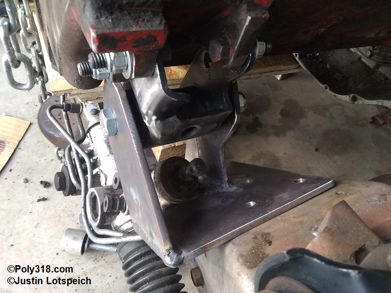
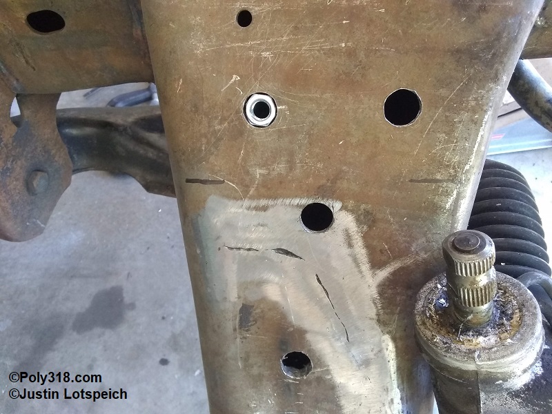
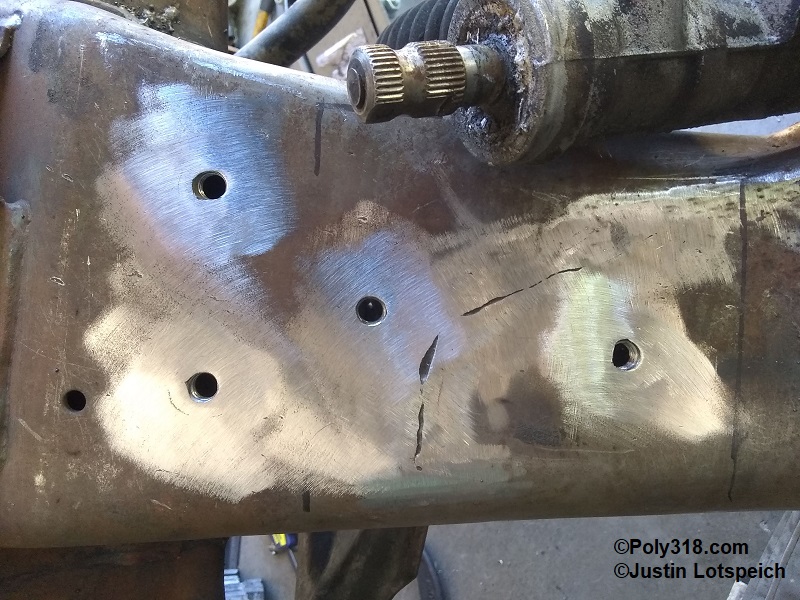
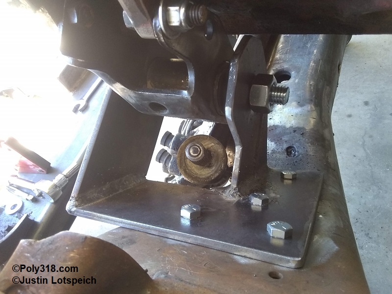
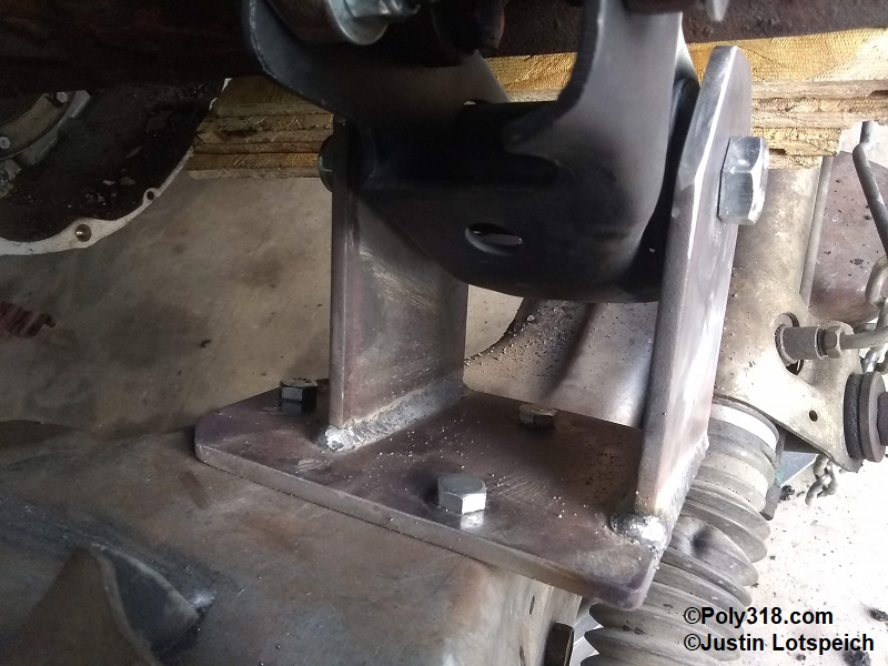
The right engine mount was relatively straightforward to design and fabricate a “C” bracket using 1/4″ plate and the three existing threaded bosses in the crossmember from the Dakota engine mount bracket. The left mount was far trickier since the rack and pinion and u-joint obstructed a straightforward “C” bracket and there were no threaded bosses in the crossmember. Using cardboard, I mocked up and took measurements, modified the design, and eventually cut out the 1/4″ plate. I drilled a series of four 13/32″ holes in the left base plate for mounting holes. With the base plates bolted or clamped in place, I used triangle welding magnets to hold one ear in position and ran a 5/8″ drill bit through the motor mount to scribe the center for the hole before center-punching and drilling them to 5/8″. With all the pieces cleaned of cutting oil, I mocked them up and pinched them together using a 5/8″ x 6″ bolt. I temporarily placed a 3/32″ thick 5/8″ washer between the back of the motor mount and the rear bracket ear to provide clearance for the motor mounts to slide into the brackets but small enough that the bolt/nut would suck the ears tight to the mount when installed. I tack-welded each end of the ears and removed both the brackets and motor mounts from the chassis/engine for final welding. I kept the motor mount and washer installed to help the bracket maintain its form during welding. Being careful to weld in 4″ sections with cooling periods in between to not overheat the metal and the rubber inserts, I jumped back and forth welding the brackets. After cooling, I installed the left bracket, scribed the mounting holes, removed the engine/transmission, drilled holes in the crossmember, and welded in 3/8″-16 nuts to match the factory Dakota threaded bosses on the right (Figures 8i – 8k). I installed the brackets and engine (Figures 8l – 8n) to mock up the transmission crossmember; I used a compass to scribe a contoured outline to the bracket ears for aesthetics that I cut out prior to painting the brackets.
Front Suspension Overhaul
I went through all suspension components to refresh them. I used a hydraulic press to remove the upper and lower control arm bushings and replace them with new. I used Moog for the bushings, rubber bump stops (upper control arm and chassis for the lower control arm), sway bar mounts, and sway bar links. For the ball joints and steering tie-rod ends, I used TRW since a last few years there have been quality issues with Moog ball joints.
I knocked out the races in the brake rotors and scrubbed the bores well with Pine-Sol, washed them with fresh water, and blew them dry with compressed air. I obtained new Timken USA-made and French-made inner and outer bearings and races, pressed in the races, and skim-coated the rotor bore and races with Sta-Lube disc-brake bearing grease. I packed the new bearings with grease and installed new Timken inner seals.
Painting the Clip and Suspension
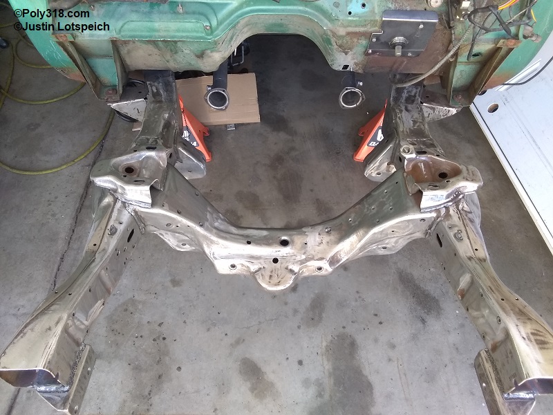
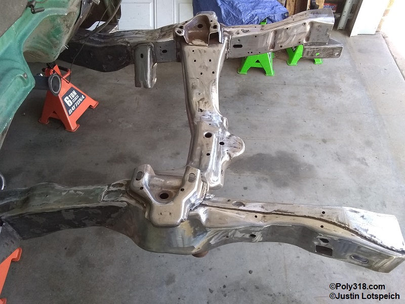
I used a pick and wire brush to remove welding flux. Using 120-grit sanding disks on an angle grinder, I cleaned up welding spatter and rounded the welds on the rails smooth for aesthetics. I used a long pry bar and a gasket scraper to clean out as much of the inside of the engine crossmember as possible since it was loaded with caked grease/dirt. I scrubbed the clip with a strong solution of Dawn dish soap and hot water to remove all oil and power-washed the clip including inside the crossmember, frame rails, and up in the spring buckets. I blew the bare metal dry with compressed air (Figure 9a – 9b).
I cleaned all the suspension components in a similar way prior to installing the new ball joints and bushings. After installing the ball joints and bushings, I hit the components with wax and grease remover, wiped them off, and blew them dry with compressed air. I masked the ball-joint boots.
For the chassis, brackets, and sway bar, I brushed on three coats of POR-15 Rust Preventive Coating in chassis black (Figure 9c). I did not paint the sway-bar/radiator core support crossmember because I want to get the front fenders fitted to the body first in case I have to cut the bracket tack welds and adjust the bracket on the crossmember. I prefer this brand and model paint because it flows out nicely with a brush, is thick, is extremely hard when cured, and is resistant to brake fluid and other caustic chemicals. For the more difficult components such as the control arms, spindles, and fasteners, I used POR-15 Top Coat chassis black in a spray can since the POR-15 Rust Preventive Coating cannot be thinned enough to shoot with an automotive spray gun.
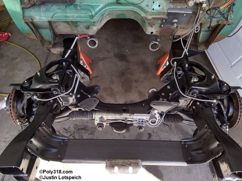
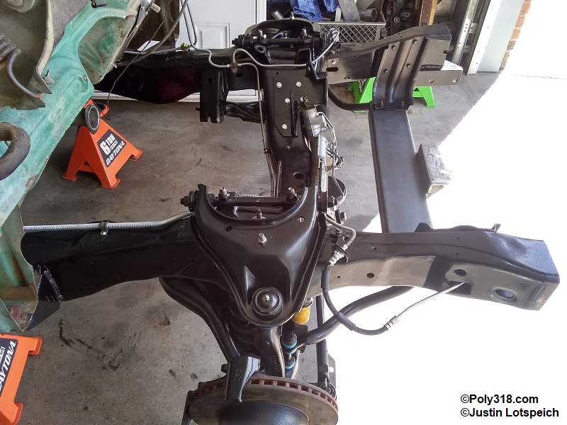
Front Suspension Assembly
After allowing 48 hours for the paint to cure, I removed all the masking tape and began assembling the components (Figure 10a – 10b). Along with the new components I described above (ball joints, bushings, etc.), I installed new KB “Excel-G” shocks. While not in the photos, I installed new calipers and semi-metallic brake shoes. I cover bending up new brake lines in another article on the brake system. I do not go into detail about assembling the front suspension since it is a straightforward process, I want to provide the torque specifications:
Lower Control Arm
-Front Nut: 130 lb.ft.
-Rear Nut: 80 lb.ft.
-Ball Joint Nut: 135 lb.ft.
Upper Control Arm
-Pivot Nuts: 130 lb.ft.
-Pivot-to-Chassis Nuts: 155 lb.ft.
-Ball Joint into Arm: 125 lb.ft.
-Ball Joint Nut: 105 lb.ft.
-Bump Stop Nut: 25 lb.ft.
Shocks
-Lower Bolts: 17 lb.ft.
-Upper Nut: 30 lb.ft. or until rubber bushings just seat but don’t crush
Spindle/Knuckle
-Wheel Bearing Nut: Tighten to 40 lb.ft. while turning the rotor. Hold rotor, back off nut, tighten nut finger tight, install cotter nut cover, cotter pin, and dust cover. Endplay should be between 0.000″ – 0.003″.
-Steering Arm to Spindle Nuts: 217 lb.ft.
-Dust Shield Bolts: 18 lb.ft.
Stabilizer/Sway Bar
-Brackets-to-Chassis Bolts: 25 lb.ft.
-U-clamp Bolts: 40 lb.ft.
-Link Nut: 17 lb.ft. or until the bushing seat but don’t crush
Steering Rack
-Mounting Bolts: 150 lb.ft.
-Tie-rod End to Steering Arm Nut: 40 lb.ft. (make sure to use anti-seize on the rack threads)
-Tie-rod End Jam Nut: 55 lb.ft.
Transmission Crossmember and Mount
The factory ’56 crossmember happens to land directly under the 1962 – 1965 TorqueFlite 727 mount flange, but the transmission rested directly atop the crossmember with no room for a rubber mount. I considered different transmission mounts as I designed the crossmember modification, ordering multiple types from the parts house to compare them. The preferred 1974+ captured A2512 was both too tall and had too narrow of the bolt pattern at 2-3/4″. The standard pre-1973 car mount A2272 was also too tall and the bolt pattern too narrow at 2-3/4″. I was hoping the short truck mount A2235 would work, but the bolt pattern was too narrow at 3-1/8″. I decided to explore outside of Mopar and grabbed a Chevrolet automatic mount with relief to find it an exact match for the 4″ bolt pattern of the 1962 – 1965 TForqueFlite 727 and a short 1-5/8″.
With the mount in hand, I laid out my cuts on the crossmember in a way that would keep the integrity of the rear wall for strength. After cutting out the pieces, I cut and welded in 3/16″ plate to reinforce the notch, installed the crossmember to mark the mount holes, and got everything drilled (Figures 11a – 11e). I still need to clean up welding slag, which I will address when I prep the chassis for paint.
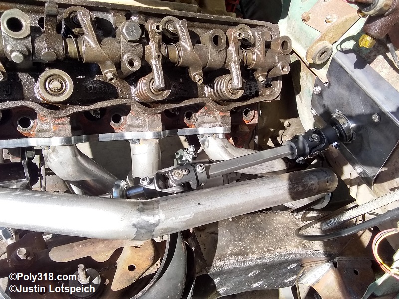
Steering Intermediate Shaft
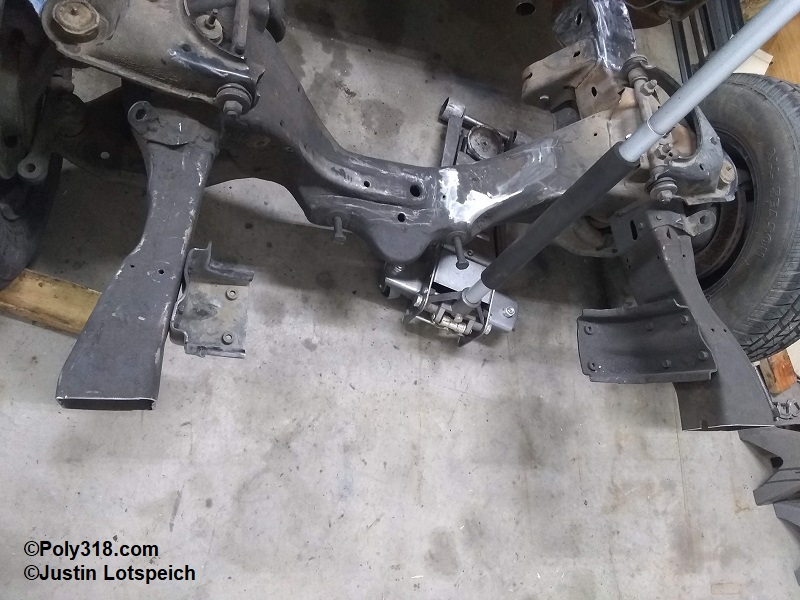
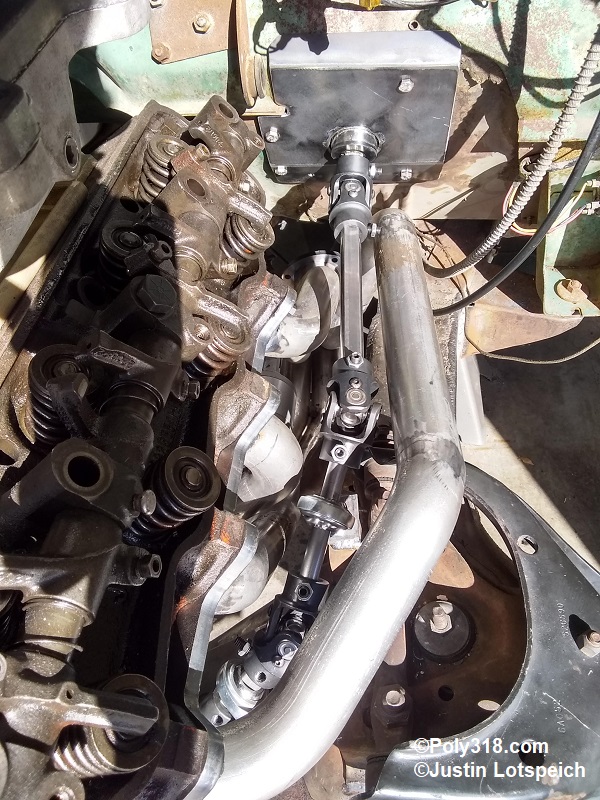
The steering setup will depend on the column configuration and exhaust manifold or header used; I built my own 30″ GM steering column wrapped in the 1956 housing with 3/4″ – 36 spline shaft and my own header to accomodate the steering and to clear the Dakota chassis and control arms. The Dakota rack and pinion takes a 3/4″ – 36 spline u-joint. With the steering shaft as high up the firewall as possible, I was able to use four 35° steering u-joints at between 29° – 33° with two support heim joints (Figures 11a – 11b). The shafts are 3/4″ DD. Remember that for every joint over two, a heim support is required near the joint to keep the shaft from rolling on itself.
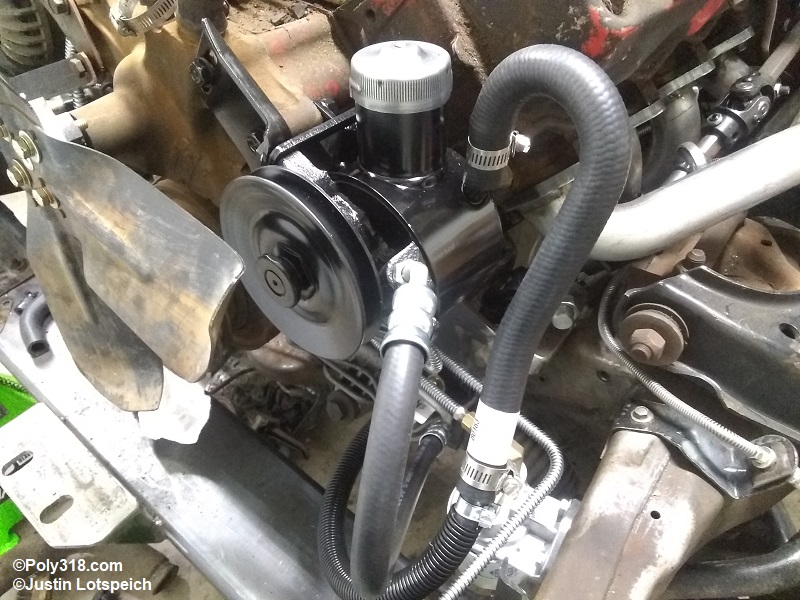
Power Steering Pump to Rack and Pinion Connection
For the steering system, I rebuilt a 1964 Dodge D100 truck Thompson (TRW) model 0.96 power steering pump because it is a direct bolt-on to the 390 stroker A-block engine and has a similar rating as the Dakota pump. The Thompson produces a maximum 1,300 psi while the Dakota produces 1,450 psi. The difference in maximum pressure shouldn’t be an issue since maximum pressure is only reached when the rack and pinion is turned to the stops. The Thompson flows 2.5 – 3 gallons per minute, while the Dakota flows 2.4 – 2.8 GPM. The different fittings and flares present a problem connecting the pump pressure port to the rack and pinion.
The early to mid-1960’s Mopar pressure hoses typically have a 3/8″ line with a 5/8″-18 male double inverted flare nut that connects to the pump, and the hose reduces to a 5/16″ with a 1/2″-20 female double inverted flare nut that connects to the steering box. The Dodge Dakota rack and pinion uses a 3/8″ line on both ends with GM o-ring flares. The pressure line takes an 18mm-1.5 male flare nut and a 16mm-1.5″ male flare nut that connects to the pump; the 3/8″ return line uses a 16mm-1.5 male flare nut at the rack and pinion and a hose clamp at the pump. Obviously, the 1960’s hoses won’t connect to the rack and pinion and the Dakota pressure hose won’t connect to the 1960’s pump. The Dakota return hose can be made to work, but the Thompson pump I’m using takes a 5/8″ return hose (note that different Thompson and Federal pumps used on 1960’s Mopars use a 3/8″ return).
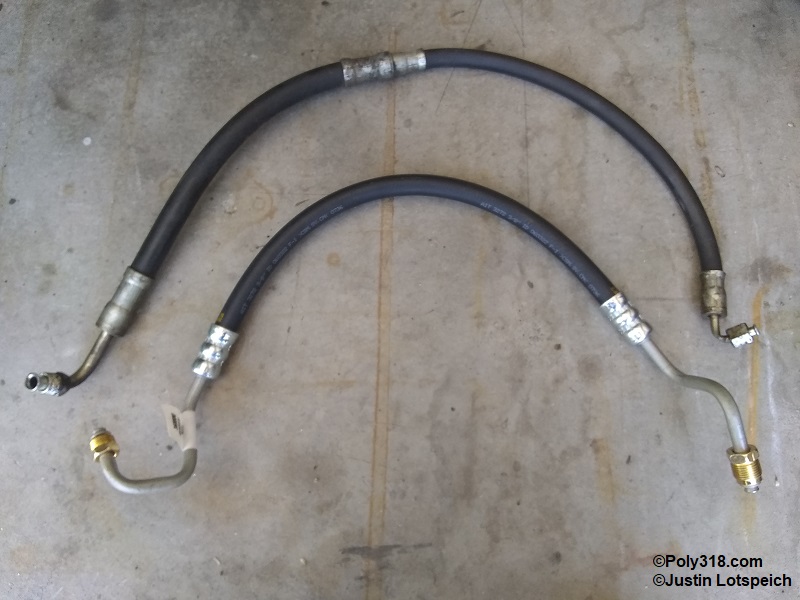
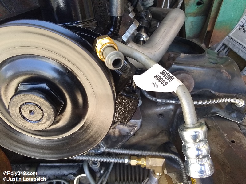
I started brainstorming with the understanding with three options: (1) find an adapter from 18mm-1.5 GM o-ring flare to 5/8″-18 double inverted flare; (2) find an adapter from 5/8″-18 double inverted flare to GM o-ring 16mm-1.5; (3) have a local hydraulic shop or Napa store build a custom hose; (4) find a hose with 3/8″ hard line on each, cut off the incorrect flare, and flare the ends as needed. Options 1 and 2 became moot when I was unable to find an 18mm-1.5 male GM o-ring flare to female 5/8″-18 double inverted flare adapter. I found such an adapter for 16mm-1.5, but that is the return port size and not an issue. From the shops I contacted, option three would end up costing around $100 for the hose. Option 4 with the GM o-ring flare requires a specialized tool that is expensive at $300. It’s a hard pill to swallow purchasing a $300 tool I will use once on a $10 hose, especially since I already have a double inverted flare tool. With limited options, I purchased an Edelmann 80069 ($12) that came on 1996 Dodge Dakota rear-wheel drive trucks hoping the pump side line was 3/8″. I also purchased a Edelmann 80448 ($8) return-to-cooler hose for the same truck model. I was happy to find both hard line ends are 3/8″. Figure 12a shows the 1964 Mopar pressure hose next to the Dakota hose.
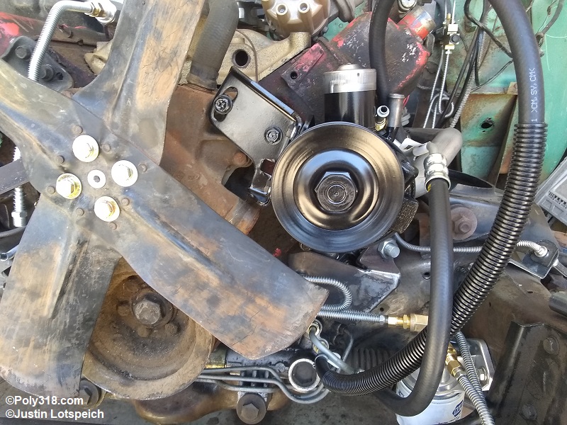
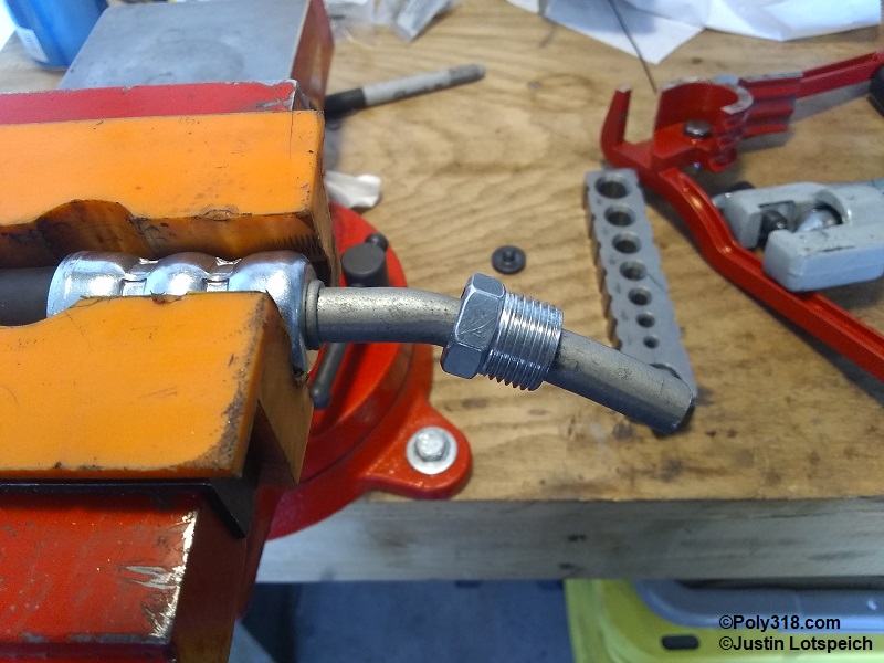
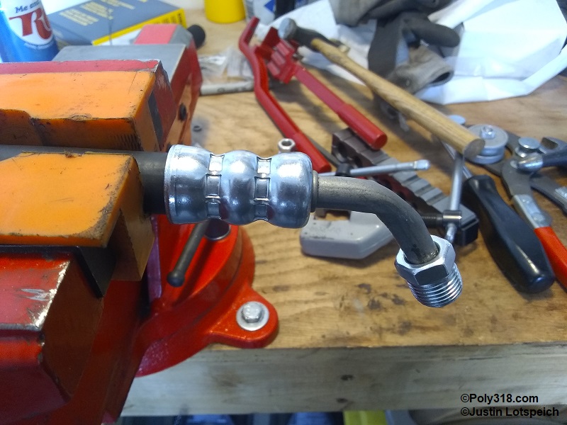
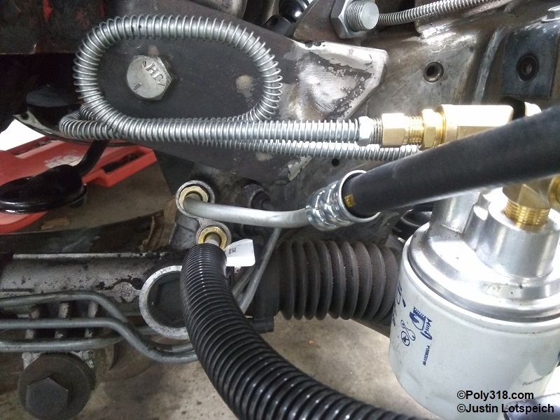
The Dakota hose, thankfully, was just short enough to make it work without having to loop it or cut it and have a hydraulic shop put in a coupler. Unfortunately, the pump end line routing was totally unusable to connect to the pump (Figure 12b – 12c). I routed the hose where it would clear the fan, pulley, and battery, and I cut off the GM o-ring flare on the pump end. I had to use a bench vice to straighten the line enough to push a new 5/8″-18 male flare nut down far enough to get the flaring clamp on the line (Figure 12d). I flared the end and used a tubing bender and a screwdriver slid into the end to get as much of a 90° turn as possible without kinking the line, although the line folded slightly on the short turn side but not enough to harm the flow (Figure 12e).
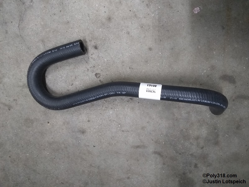
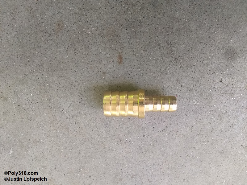
The return line took some consideration as well since I had to figure out how to go from 3/8″ hose to a 5/8″ nipple while making a 180° turn out of the pump. One option was to use 5/8″ hose at the pump, route it into a 180° upside down “U,” and somewhere in the hose leading down to the rack and pinion use a brass 5/8″-to-3/8″ barbed reducer that would tie into the Dakota return hose. I mocked up this option with a length of 5/8″ power steering hose, and the 180° turn without kinking it stuck up far above the valve cover and looked awful. I spent a few hours searching and reading through parts catalogs and came upon a return hose 80162 for a 1982 – 1984 Chevrolet Cavalier that is 5/8″ with a clean 180° turn (Figure 12f). I the hose at the pump connection to lower the turn as much as possible and then cut the bottom of the hose where the Dakota hose mated up and routed away from any rub points. Using a 5/8″-to-3/8″ barbed reducer (Figure 12g), I finished attaching the return hose. Figures 12h – 12j show the finished power steering configuration.
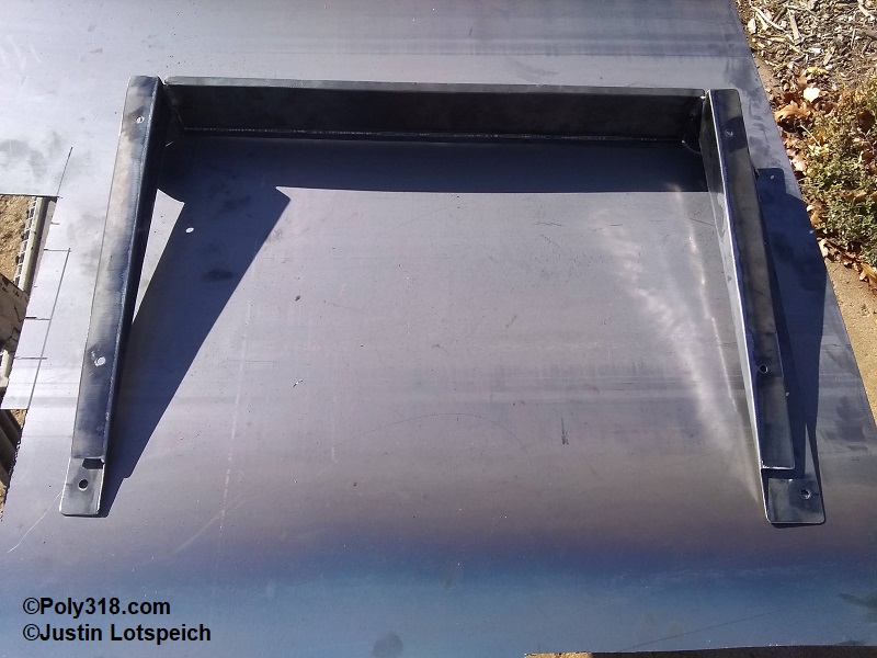
Radiator Mounting Shroud
The factory 1956 Dodge radiator incorporates a steel sheet metal mount that doubles as a shroud to direct air flow through the core support hole into the radiator. In one of Mopar’s early and odd attempts at using an offset-pinion rear end, the factory engine/transmission is installed at an angle with the transmission output shaft pointing toward the right of the chassis to align with the pinion flange. Subsequently, the radiator mounting shroud has an angle built into it so the cooling fan remains square with the radiator. Because I have installed the engine parallel with the chassis, the factory radiator is now cocked out of square with the cooling fan. To resolve the issue, I built a new mounting shroud from 16 gauge steel plate that accepts a later radiator (Figures 13a – 13b). Notice in Figure 13c the angled factory mounting shroud versus my square mounting shroud, although this photo shows a prototype shroud that I built to install a later radiator after my factory 1956 core gave up the ghost. After I researched all 1956 – 1969 Mopar radiators with center inlets and left outlets to match my A-block with a pre-1970 short water pump, I found that the 1965 – 1966 Dodge Dart radiator is just the correct width and height for the 1956 Dodge core support, and it is a readily available radiator that will likely not go out of production for a long time compared to the non-existent 1956 Dodge aftermarket radiator.
Post-clip Ride Height
I lowered the car onto the ground with the same wheels/tires installed and installed the A-block 318 and TorqueFlite 727 I used for mock-up. I found that the front dropped some and measured the rear of rocker to garage floor at 10″ (which was also the stock baseline I measured) and the front rocker to floor 10″, which was 1/2″ lower than the factory baseline. The 8.8″ Ford rear end and custom leaf springs I installed added 2″ of lift in the back to where the car loaded with engine, transmission, and front sheet metal has a nice 2″ rake with 12″ from floor to rocker at the rear and 10″ at the front of the rocker.