Poly 318 Cooling System, Thermostat, Overheating, & Aluminum Radiators
(applicable to poly 277, 301, 303, 313, 318, 326 and LA 273, 318, 340, 360)
Introduction
There can be confusion about an A-block’s cooling system, the thermostat’s function, proper thermostat selection, overheating, water pumps, aluminum radiators, and stop-leak additives ranging from people telling others to not run a thermostat to people claiming an aluminum radiator must be grounded to the body. To address the confusion, I dig into the A-block cooling system (which applies to LA and B/RB and most engines for that matter) and discuss areas to examine during overheating diagnostics. This is a lengthy page that includes the topics
- Thermostat Mechanics and Coolant Flow
- Engine Operating Temperature and Overheating
- Water Pump Selection (Standard or High-flow)
- Thermostat Myths
- Thermostat Selection
- Radiator Sizing
- Aluminum Radiator Mounting and Protection from Electrolysis, Galvanic Corrosion, and Pitting Corrosion
- Zinc Anodes for Preventative Maintenance
- Troubleshooting Overheating
- Dangers of Using Stop-leak Additives
Thermostat Mechanics and Coolant System Flow
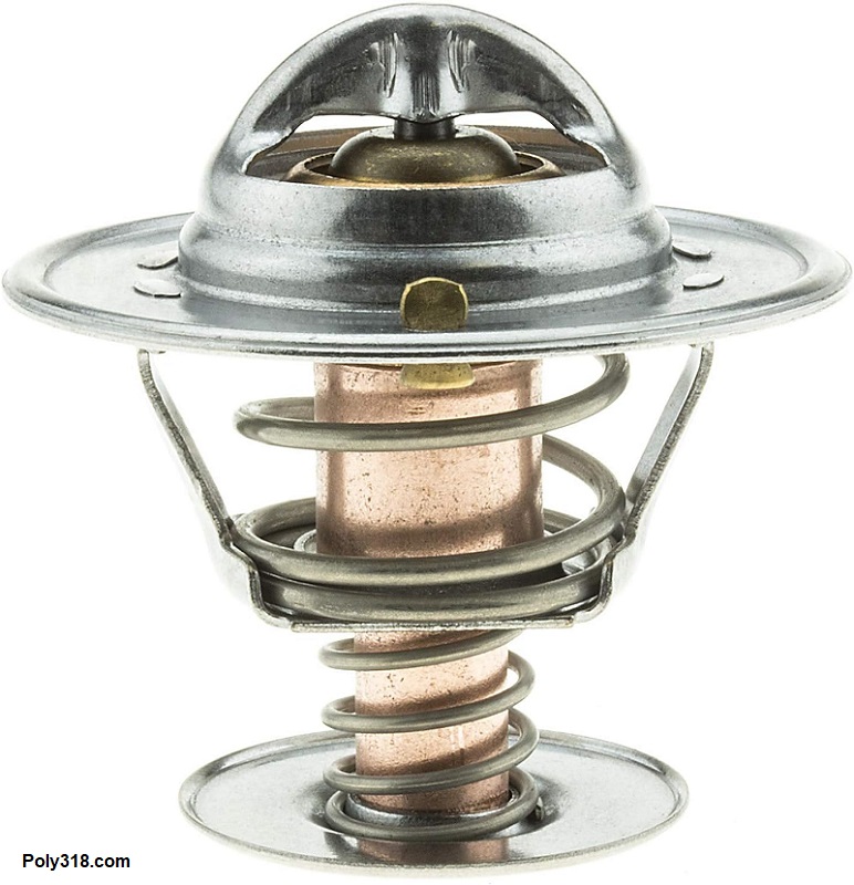
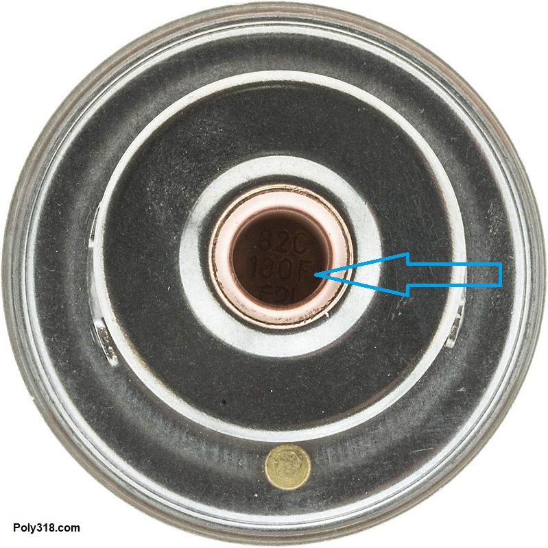
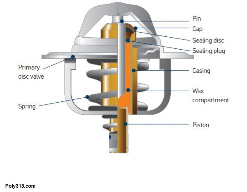
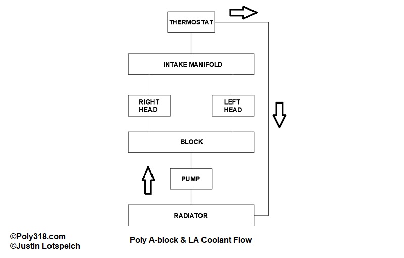
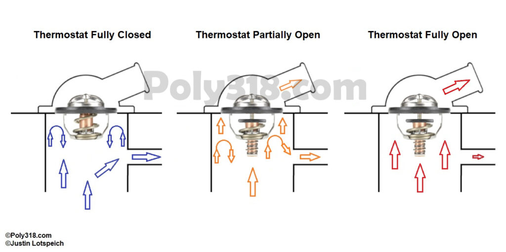
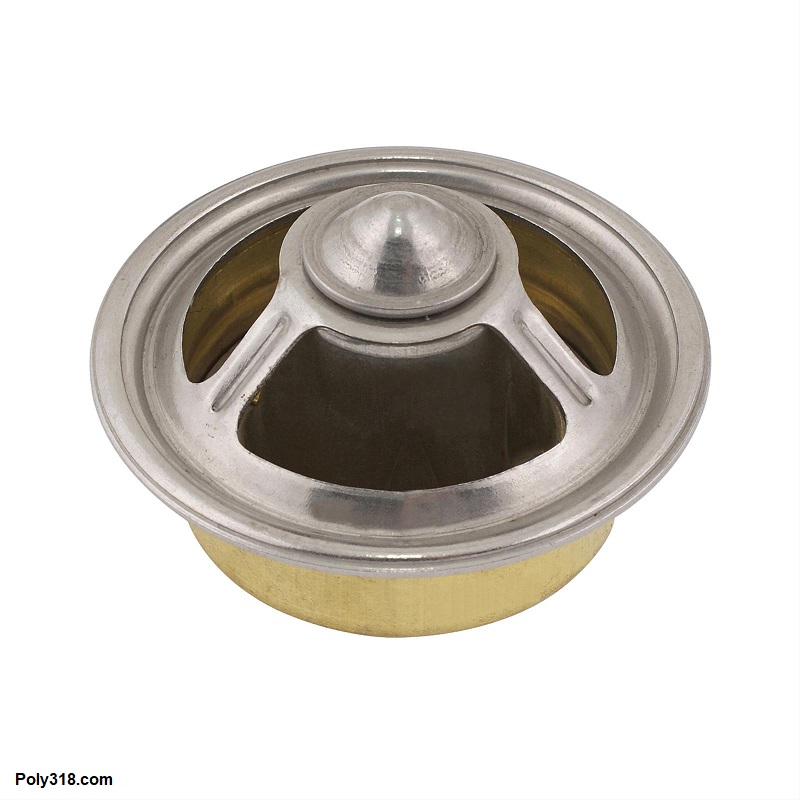
The cooling system is made of multiple key components including the radiator and cap, fan and shroud, water pump, engine block, cylinder heads, intake manifold, thermostat, and hoses. These components each must be healthy and designed in tune with each other for the system to function properly. The thermostat is a key component and is a variable-flow thermal valve. Figures 1a shows a typical standard-flow thermostat upright as it should be installed with the spring facing the engine block. Figure 1b depicts the temperature rating of the thermostat, which is the temperature the thermostat will do its best to maintain; it is not the temperature at which the thermostat opens or is wide open, which I discuss below, nor is it a guarantee that the engine will run at the rated temperature. Figure 1c identifies the different components of the thermostat. As the coolant circulating only through the engine warms from cold start, the thermal wax in the cylinder begins expanding, which pushes the valve open. Figure 1d shows the flow of an A/LA engine, which is how most V8 and 6-cylinder engines work. Once the thermostat begins opening, hot coolant enters the top of the radiator where it flows down through the tubes and the heat is dissipated via the fins and air blowing across/through them, flows out of the bottom of the radiator into the water pump, through the block, through the cylinder heads, through the intake manifold, through the thermostat, into the radiator to repeat the cycle.
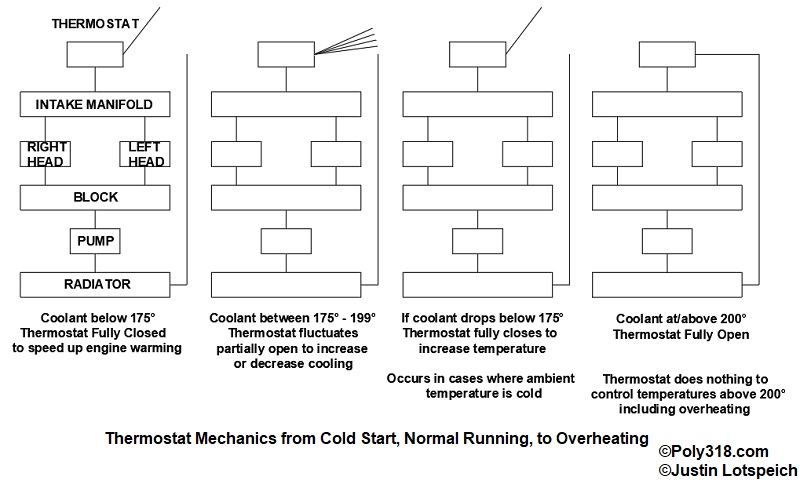
The thermostat’s main functions are to allow the engine’s temperature to rise as quickly as possible upon cold start when engine components are most susceptible to wear, to provide the cabin with heat for window defrosting and comfort, and to help maintain a stable minimum operating temperature close to the thermostat’s rating, although this minimum temperature depends on many variables. A healthy system no matter the ambient temperature will maintain an intake manifold coolant temperature within an approximate 30° range of 175° – 205°. Referring to Figure 1e, when a cold engine starts, the water pump pushes coolant through the block, heads, intake manifold, and heater core (if installed). The coolant runs up against the bottom of the closed thermostat valve and is forced through the bypass hose back into the water pump where it cycles back through the engine without going through the radiator aside from a minute volume of coolant that may pass through the bleeder hole in the thermostat plate (if equipped) or up around the edge of the thermostat plate depending on how much wiggle room is between the intake manifold flange and thermostat housing. The coolant in the engine thus builds temperature much quicker than it would without a thermostat where cold coolant would enter the radiator and be cooled.
Referring to Figure 1f where I use a 180° thermostat as an example, the thermostat is fully closed at cold start. Once the coolant reaches around 175°, the thermostat valve begins opening gradually to allow some hot coolant into the radiator to cool while most is still bypassed into the block to continue building heat. The thermostat will fluctuate opening more or less, and thus bypassing more or less, between about 175° and 200° to maintain a steady normal operating temperature depending on the ambient temperature, humidity, air flow, engine rpm, etc. By 200°, the thermostat is wide open flowing as much coolant as possible through the radiator, but there’s an often-overlooked component at work even with a wide-open thermostat: the thermostat by design is restrictive even when wide open so that coolant flow is slowed. I discuss the physics more below regarding standard-flow and high-flow pumps, but the basic principle is that the metal in the radiator tanks, tubes, and fins can absorb and dissipate to the air only so much heat for any given amount of coolant making contact. If the coolant rushes over the metal surface too quickly, the heat will not transfer, and the coolant will get hotter and hotter. A-blocks, like most iron-head V8s, are designed to perform best between 180° and 205°, and our example 180° thermostat will decrease and increase its flow volume to help regulate the temperature so that when the engine begins heating up too much idling in heavy traffic, more coolant flows through the radiator, but when the engine begins cooling down too much on the open road, less coolant flows through the radiator in order to build heat in the engine.
Engine Operating Temperature, When to be Worried, and When to Shut Down
“Normal” operating temperature depends on multiple variables including the engine’s construction (cylinder wall thickness, water jacket sizes, pump flow, etc.), ambient temperature, relative humidity, elevation, and driving conditions. For example, an overbored A390 with 10.5:1 compression will want to run hotter in traffic than a stock A318 at the same ambient temperature since the 390’s combustion dynamics produce more power and therefor more heat, and the cylinder walls are thinner to where more of that heat transfers to the coolant rather than out the exhaust. Similarly, a stock A318 in traffic at 65°F ambient will want to run cooler than the same engine in traffic at 100°F ambient since the colder ambient air blowing through the radiator can absorb more heat and is more efficient at cooling the system. Similarly still, an A318 at sea level in traffic at 85°F ambient will want to run cooler than the same engine in traffic at 85°F ambient at 5,000 feet elevation since the thicker air at sea level is more efficient at cooling. In these ways, one A-block may have a “normal” operating range of 170° – 190° while another 185° – 205°.
“Safe” operating temperature is different than “normal” operating temperature. Regardless of the engine, ambient temperature, humidity, elevation, and other factors, an ideal healthy cooling system on an iron-head A/LA should keep the engine between 175° and 205° under normal driving conditions. The cooling system should be built for that purpose, as in an engine that sees traffic in a 100° ambient desert city may need a larger radiator, electric fan(s), etc. than an engine that sees traffic in a 70° ambient coastal city to keep the engine within a safe operating range. Depending on all the variables, the engine may climb to 210° without causing concern in heavy traffic or pulling grades/towing but should immediately decrease to a safe operating range once out of traffic or no longer pulling the grade. 215° should draw careful focus on the temperature gauge for further increases since the engine is now overheating outside of the safe operating range, and 225° should be the time to pull over and shut off the engine to avoid unnecessary strain on the head gasket, engine oil, automatic transmission fluid (if it shares the radiator for cooling), and other components. Running the engine at or above 225° for prolonged amounts of time is asking for trouble and should only be done in an emergency at the risk of harming engine and possibly the transmission components. Keep in mind that automatic transmission fluid begins deteriorating exponentially at 210°F and is junk by 240°.
Water Pump and Thermostat: Standard-flow or High-flow?
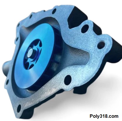
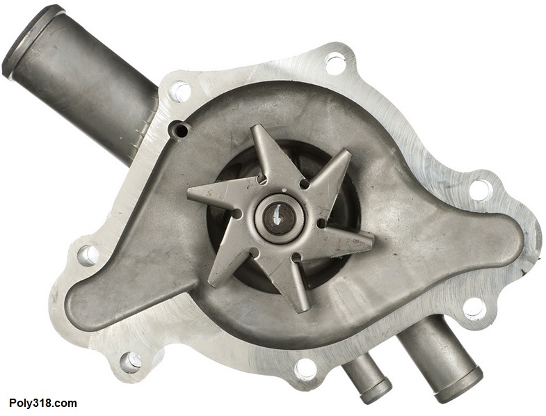
As with many performance components, context is everything. The corporate-owned magazines and retailers will swear a high-flow system is superior to a standard/OEM system regardless of context, but no one from those companies will be helping you when your engine is overheating on the side of the road. The vast majority of A-blocks and LA engines from 277 stockers to 402 strokers with a healthy cooling system should maintain a normal operating temperature between 175° and 205° in the summer using an OEM standard-flow water pump and thermostat. The aftermarket suppliers of high-flow pumps (Figure 2a) are obviously in business to sell their parts, and some high-performance builds that produces a lot of heat–such as a road-course car twisting 7,000 RPM for half an hour–may benefit from a high-flow pump when the rest of the cooling system is sized properly. However, what the high-flow pump advertisements don’t explain is that pushing the coolant too quickly through the engine can in many cases be less efficient at cooling the engine than the slower flow of an OEM pump (Figure 2b) and may actually cause overheating. While I’m not a hydraulic physicist and have chosen not to even try to figure out the algebra, the different metals in the radiator (aluminum, brass, copper, etc.) have physical limits to how much heat they can absorb in a given amount of time in relationship to how much coolant contacts the metal. If the coolant flowing through the radiator tubes moves too quickly, the tubes and fins will not have enough time to absorb the heat, which means less heat will be vented to the air. As less heat is transferred into the air, more heat builds in the engine and coolant, exponentially becoming hotter. I wouldn’t recommend a high-flow pump on anything except more extreme builds where high-flow pumps have been proven to be more effective. I would certainly pass on a high-flow pump for stock and performance street cars since an OEM pump matched with a healthy cooling system should keep the temperature within the approximate 175° – 205° range. If such an engine cannot maintain that range under normal driving conditions, there is an issue causing overheating that should be diagnosed before experimenting with a high-flow pump.
One component to consider experimenting with is a high-flow thermostat (Figure 2c). The quality high-flow thermostats like Mr. Gasket 4367 are extremely good quality and provide a larger orifice for less restriction, but they still choke the coolant as it passes through. For some builds, the high-flow thermostat may not slow the coolant enough and cause the engine to run hotter, but for others it might improve cooling. Only trial and error will determine the choice between a standard-flow and high-flow thermostat. Another benefit of the high-flow thermostats is that any larger flakes of rust broken free in the engine can pass through the orifice and into the in-line filter in the upper radiator hose (I recommend a Red Line model 951), whereas larger flakes can block a standard-flow thermostat or get wedged in the valve and stop it from fully closing.
Debunking Thermostat Misinformation: Engines that Run Hot or Overheat & High-performance Engines
Now that I’ve given an overview of the system and “normal” and “safe” operating temperatures, hopefully it is clear that the thermostat has limited control over the minimum temperature and absolutely nothing to do with the maximum temperature at which the engine will run. An intimately familiar example that follows the typical cooling system physics is my 1975 Chevy C20 long-bed pickup truck that has been my parts-and-lumber-getter for years. Here in Denver, Colorado at 5,600′ elevation, our average nicer winter days don’t get out of the 30°Fs by midday. The truck has a 350 Chevy engine, 195°F thermostat, OEM pump, large four-row brass-copper radiator, mechanical fan, and a properly sized and installed shroud. When I cold-start the truck when its 20°F ambient, the closed 195° thermostat forces the coolant to bypass the radiator for a longer period of time than a 180° would to heat the cabin and engine oil/components quicker, and it pushes the “normal” operating temperature range farther up to around 185° – 205° compared to the 175° – 205°. But even with this higher rating thermostat, the engine cruising down the road on a 30°F day fully warmed runs at 175°. In this situation, the thermostat is closed all the time to keep the coolant circulating only in the engine and heater core. If I were to use a 180° thermostat that opens at around 175°, the engine would likely run closer to 155° since the freezing cold coolant from the radiator would periodically flow into the engine and crash the temperature. If I removed the thermostat altogether, the radiator would over-cool the engine to where I doubt the engine would get above 100°, if that. In this example, the 190° thermostat is doing its job to keep heat in the engine, but it has no control over the super-cooling variables that restrict the engine to 175°.
On the other extreme, if an engine’s cooling system is allowing it to reach 215° in normal driving in 80° ambient temperature, there is an issue with the system that no thermostat or lack thereof will resolve. The claim some people make to run a 160° thermostat in an attempt to fix the overheating is mistaken and counterproductive. Upon cold start, the 160° thermostat will remain fully closed until the coolant reaches about 155°, and by around 180° the thermostat will be completely open. The coolant temperature continues rising from that point as high as it wants until it reaches a point where the system’s cooling capacity stabilizes the temperature, 215° in this example. The 160° thermostat does absolutely nothing above 180° aside from restrict the passage via its body to regulate coolant flow. What the thermostat does do, however, is extends the time it takes the engine to reach the normal operating temperature lower end of 175° because the coolant begins entering and being cooled by the radiator at 155° versus the 175° of a 180° thermostat. This prolonged warm-up period puts more strain on the wear components in the engine (and the transmission if the radiator cools the fluid).
Another claim people make is that running no thermostat will solve overheating issues, which is likewise mistaken. A system without a thermostat results in extremely prolonged warming, poor cold-driving performance, uncomfortably slow cabin heating, and an engine that is prone to larger temperature swings in different driving conditions (e.g. traffic vs. open road) since there is no valve to increase and decrease the flow to the radiator to help regulate and smooth out the temperature variations. In the example of this overheating 215° engine now without a thermostat, once the engine hits 200° from cold start it will continue rising until the temperature stabilizes at 215° and possibly higher since the lack of a thermostat means the coolant is flowing even quicker through the radiator without enough time for the metals to absorb the heat. Both the 160° thermostat and no-thermostat approaches to band-aid an overheating engine misunderstand that the thermostat has absolutely no control over limiting the maximum temperature the engine reaches.
The last claim, although rarer in frequency, is that running a 160° or no thermostat will produce more horsepower. There are a few issues with this claim, most of which I just explained regarding the thermostat’s limited ability to regulate minimum temperature and no ability to stop and engine from running at a temperature higher than the point where the thermostat is wide open. The other larger issue is that A-blocks, as with other internal-combustion engines, actually produce more power the hotter they are up to a point, not the colder they are. An A-block will produce more power at 200° due to the combustion chambers being hotter than if the coolant were 160° and the combustion chambers are cooler, proven many times over on the dyno and at the race track. While we’ll never know who started the misinformation, I wonder if it stemmed from the fact that a colder air-fuel mixture has a denser molecular structure and packs in more power potential by volume than a warmer air-fuel mixture, so someone possibly assumed the best thing to do would be to try and cool the entire engine as much as possible to keep the air-fuel mixture cooler. The irony is that in the quest for more power by running a 160° or no thermostat, the combustion chambers are robbed of the crucial higher temperatures that have a far greater impact on power than the air-fuel mixture temperature when comparing an engine running wide-open throttle at 160° and another doing the same at 200°.
Thermostat Selection
So how do we select a thermostat for our A-block? In most circumstances, engines usually running in climates above 55°F will benefit from a 180° thermostat; engines usually running in climates below 54°F will benefit from a 195° thermostat that pushes the normal maintained temperature up to assist with the engine building temperature quicker at startup to limit engine wear, for quicker cabin heating, and for maintaining more heat in the engine to compensate for the colder ambient air flowing through the radiator and engine compartment. Using my 1975 Chevy C20 as an example, the engine running in 25° ambient may run at 175° with a 195° thermostat rather than at 160° with a 180° thermostat, which is where it used to run when I first bought it before I replaced its 180° thermostat with a 195°. For most stock engines with a cooling systems functioning properly, a standard-flow thermostat and water pump work just fine and likely better than if a high-flow pump and thermostat were installed. Remember that millions of A-blocks, LA, B, and RB engines with standard-flow pumps and thermostats ran within safe normal operating temperature from 1956 into the 1990s. For engines that run in extreme heat or under extreme driving conditions, a high-flow system might help, but I would first upgrade to a larger radiator and electrical cooling fans before I touched the water pump since more cooling surface area and higher airflow volume will likely resolve the issue. Thermostats and other components are readily available through Summit Racing, JEGS, Speedway Motors, Rock Auto, Napa Auto Parts, and other retailers.
Radiator Sizing
Before the advent of mass-produced aftermarket aluminum radiators, a four-row brass-copper radiator was the best choice for performance A-blocks, especially those that would see traffic or sitting in line at the track in hotter climates. Stock or mild engines and those in cooler climates should cool fine with a good two-row or three-row brass-copper radiator. Now that aftermarket aluminum radiators are affordable and can be had in many different sizes for many makes/models/years, a good two-row aluminum radiator (4-row or more equivalent) is a great choice since aluminum is stronger than brass-copper radiators, lighter, and the tubes are larger providing superior tubing-to-coolant and tubing-to-fin contact area.
- Note: A proper fan and shroud are just as important as the radiator. The factory A-block fan will pull plenty of air and keep the vintage look, so long as it has a proper shroud to direct the air. Before upgrading to a different mechanical fan or installing an electric fan, try a properly sized shroud.
Should an Aluminum Radiator Use Rubber Mounts or Be Grounded to the Body/Chassis?
With the abundance of aluminum radiators on the market, and with aluminum radiators being more efficient at cooling the engine than brass-copper radiators, I wanted to discuss the best way to retrofit a classic vehicle with an aluminum radiator. There is a lot of mixed information online about using or not using rubber mounts, grounding or not grounding the radiator, electrolysis/corrosion, stray voltage, and other topics that easily muddy the topic.
On a classic-car forum thread where the original poster asked about converting his damaged brass-copper radiator to an aluminum one, someone replied that aluminum radiators should use rubber pads between the radiator mount and steel core support to dampen vibration and then a dedicated ground wire secured to the radiator and body since the rubber pads disconnect the ground. There are two misunderstandings in this recommendation that have serious consequences for anyone who takes the advice at face value. First, the main reason for using rubber to isolate the aluminum radiator from the steel core support is to isolate the radiator from the electrical system. Second, an aluminum radiator should never have a dedicated ground that connects it to the electrical system.
If an aluminum radiator is grounded to the chassis through the steel core support or a dedicated ground wire/strap, the cooling system has the potential of turning the coolant acidic over time producing electrolysis that rots out aluminum radiator and, if installed, heater core. There must be specific circumstances to turn the coolant into acid, but a key component is the relationship of the battery ground to the radiator. An automotive electrical system relies on a series of properly-sized ground cables/straps/wires to create strong paths back to the negative battery terminal. Excluding discussion of the smaller wires that ground electrical components to the body/engine/chassis, a common primary grounding configuration for a battery mounted in the engine compartment goes something like
- Heavy-gauge cable from the negative battery terminal to the engine block
- Heavy-gauge cable or strap from the engine block to the chassis
- Heavy-gauge wire or strap from the engine block to the body
- Heavy-gauge wire or strap from the front of the body to the chassis
- Heavy-gauge wire or strap from the back of the body to the chassis
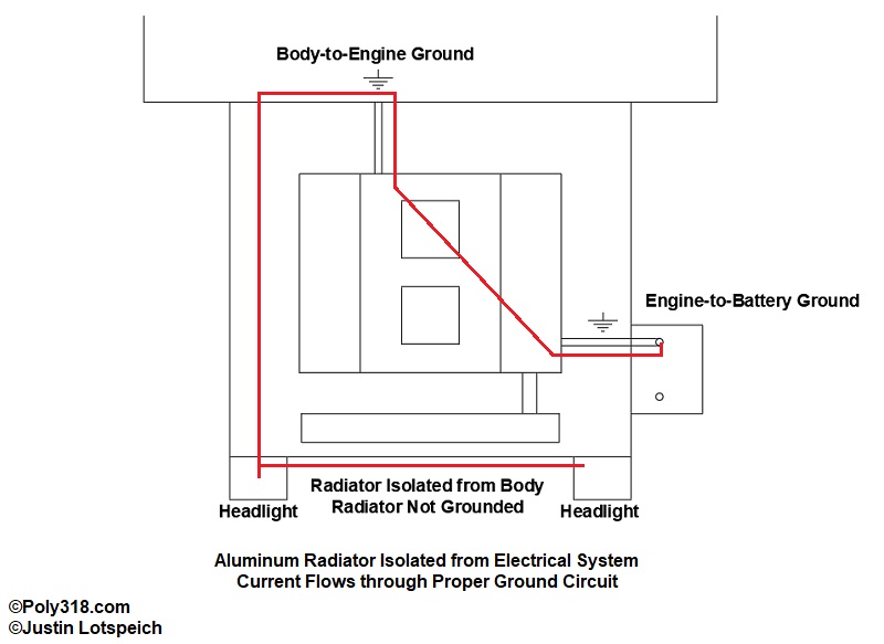
Here’s where the aluminum radiator comes into play. If the aluminum radiator is grounded to the body (core support) through the mounting flange or a dedicated ground wire and current can find a shorter path through the radiator and coolant to ground than if the radiator were not grounded, the current will take that shortcut through the radiator. For example, imagine a 1966 Dodge Coronet that has an aluminum radiator isolated from the core support and all other grounded components by using rubber pads (Figure 3a). The battery is installed on the left front of the engine compartment. The negative battery cable is grounded to the left side of the engine block. There is a dedicated ground strap running from the back of the block to the body firewall. The headlights are grounded to the core support. Turn the headlights on, and the current must flow from the headlights, through the inner fenders, through the cowl, into the engine, over to the negative battery cable, and into the battery. Just estimating, let’s say the route is 15 linear feet the current must travel from the headlight to battery.
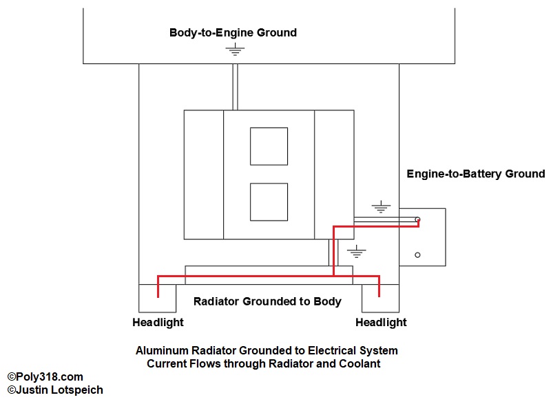
Now let’s install an aluminum radiator without rubber pads and ground it to the core support (Figure 3b). Turn the headlights on, and the current now has a shorter path to ground by going through the core support into the radiator, through the bottom and/or top radiator hose via the coolant, into the engine block, through the negative battery cable, into the battery. Yes, antifreeze can carry current, and not much is required to cause issues. Let’s say this route is 8 linear feet from the right headlight to the battery. The current will follow the shortest path to ground. Now consider the horn current. Add an electric fan that is grounded to the core support, and we have even more current running through the coolant to ground. As the coolant is charged, it becomes acidic through chemical reactions and starts galvanic corrosion. This issue of the coolant carrying current is referred to as “stray current” and can reek havoc on the most cathodic material in the cooling system, which is the aluminum radiator, aluminum heater core, and aluminum intake manifold, if equipped. The ensuing electrolysis will corrode through the thin aluminum tubes first, destroying the radiator and heater core. Copper-brass radiators of old grounded to the core support couldn’t care less about acidic coolant since the iron of the engine was more anodic and took the corrosion beating.
Due to the danger electrolysis poses to aluminum radiators, leading aluminum radiator manufacturer warranties like Griffin’s to Be Cool’s require that the radiator is properly isolated from the electrical system, and the warranties will not cover damage from electrolysis. By using rubber pads between the radiator flange and core support and by ensuring no brackets, parts, or wires touch both the radiator and body to form a ground, the electrical current of the headlights, horn, cooling fan, and any other components are forced to take the longer, appropriate path through the body or chassis and engine back to the battery.
How Common Is Radiator Failure Due to Stray Current and Galvanic Corrosion?
Having spent all this time discussing stray current, readers might be disappointed to hear that for aluminum radiators that are properly separated with rubber pads and not grounded, galvanic corrosion makes up an extremely small fraction (as in the single digits) of radiator failures. The more likely cause of aluminum radiator failure, especially when they are isolated from the electrical system, is from “pitting corrosion,” which makes up something the vast majority of failures. The three leading causes of pitting corrosion are improper antifreeze-to-water ratio, using tap water rather than distilled, and a dirty system with suspended particles that are guaranteed in our 1920’s – 1980’s engines. The worst is a combination of all three conditions.
Running an in-line screen in the upper radiator hose is extremely wise to catch larger rust debris that will clog the thermostat and radiator tubes (I recommend the Red Line model 951 filter that is easily cleanable without losing coolant). However, no filter will catch the smaller particles in the system that turn the coolant a reddish-brown/orange color. The suspended particles settle when the engine is off and pack into the nooks and crannies of the radiator tanks and block out the antifreeze’s anti-corrosion chemicals. With the lack of these chemicals, pitting corrosion sets in. The best visual for pitting corrosion is what we see when taking off the radiator hose that has been secured to an iron or aluminum thermostat housing or water pump and we find flaking metal chunks and deep pitting. That’s pitting corrosion where the fine particles in the coolant pack into the gap between the hose and metal, blocking out the antifreeze’s protection.
Along with fine particles in the coolant causing pitting corrosion, if the coolant mixture uses tap water and/or is the incorrect ratio with too much water, the pitting corrosion accelerates. It’s common for the mixture ratio to become skewed toward more water when people top off their radiators or overflow tanks with straight water and never match it with antifreeze.
Pitting corrosion is the number one cause of aluminum radiator and heater-core failure often due to lack of proper precautions and maintenance. To hold the corrosion at bay, an in-line filter and 50/50 mixture of antifreeze using premixed or concentrate with distilled water should be used, and the system with older cast-iron engines should be flushed more frequently to dislodge the settled particles and to renew the coolant. Pitting corrosion was much less of an issue when our engines were ten years old in the 1970s and radiators and heater cores were brass-copper, but our engines are now archaic hunks of iron rotting from the inside out and have plenty of rust debris in the block and heads even after hot tanking and flushing during a rebuild. When the radiator is properly isolated from the electrical system, the cooling system is flushed for routine maintenance, and the proper coolant ratio is maintained using distilled water, an aluminum radiator will last and outperform a brass-copper radiator in cooling.
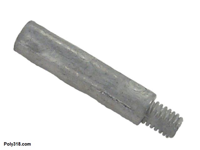
Protecting the Cooling System with Zinc or Magnesium Anode
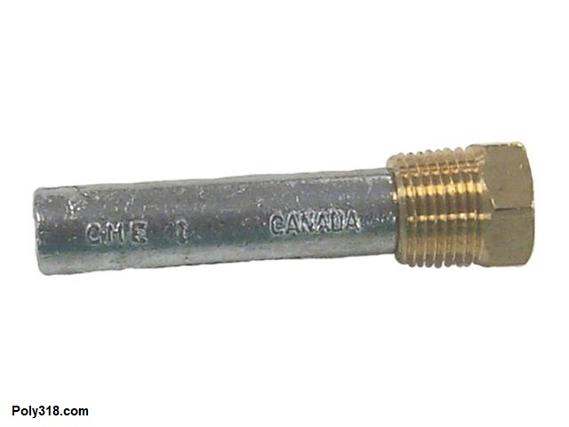
I don’t recommend using a zinc anode as a band aid for an aluminum radiator not properly isolated from the electrical system suffering from acidic coolant and electrolysis. However, they are a good and inexpensive (under $10) preventative part to use on a system with an aluminum radiator and/or heater core properly isolated from the electrical system. The zinc rod is more anodic than the aluminum in the system and will deteriorate first. The anode should be checked during normal cooling-system maintenance, although it should never need replacing if the system is properly installed and coolant maintained. If the rod quickly deteriorates, the cause of the electrolysis should be diagnosed. The most common type of automotive zinc anode includes a plug that screws into the bottom radiator tank in place of the drain petcock, although they can be placed in an intake manifold port. Sierra Marine (Summit Racing carries them) produces quality zinc anodes made in Canada in different NPT sizes. Referring to Figures 4a – 4b, the most common sizes for aluminum radiators is 1/4″ NPT plug with a 1.75″ long x 3/8″ diameter anode 18-6059 (replacement 18-6135), 2″ long x 3/8″ diameter anode 18-6136 (replacement 18-6053), or 2″ long x 1/2″ diameter anode 18-6060 (replacement 18-6052). The anode can be cut to length for clearance as needed. Another design puts the anode on a rod that swings from the radiator cap, but I don’t like them because they can bounce around and fold over the nearby tube(s).
Troubleshooting Overheating Engines
If the engine runs above 205° under normal non-traffic conditions, especially when the ambient temperature is under 85°, the cooling system and vitals need inspecting and addressing including temperature gauge/sending unit, airflow (fan/shroud/radiator fins/grille), coolant condition and level, radiator flow (clogged tubes), water pump flow (bad impeller and/or clogged chamber), clogs in the system, air pocket at the thermostat or in the water-pump chamber, exhaust heat riser valve (stuck shut), ultra-lean air-fuel mixture (see my carburetor tuning article), and overly advanced timing (see my article on timing an engine). If I suspect a cooling problem on a vehicle, the very first step I do is confirm that the temperature gauge is reading correctly, which I do by shooting a reliable infrared temperature gun at the thermostat housing. If the temperature there reads different from the gauge, then the gauge or sending unit is the issue. Many times, an overheating problem that did not begin overnight is due to inadequate air movement through the radiator often due to a poorly designed and/or installed shroud. If the issue happened overnight when no mechanical work was done to the cooling system, a broken water-pump belt, low coolant level (which means there is an issue leading to loss of coolant), a thermostat stuck closed, or a clog in the radiator or system are likely culprits. If the issue started after working on the cooling system or engine fueling and ignition, an upside-down thermostat, air pocket surrounding the thermostat, ultra-lean fuel mixture, or extremely advanced timing may be the cause. A factory exhaust manifold heat riser valve stuck closed can also overheat that cylinder bank and lead to higher coolant temperatures among other issues. I start with the most plausible possibility based off when the overheating started, under what conditions, and depending on what work was done prior to overheating and work my way to the more unlikely culprits.
Leaks and Using Stop-leak Products
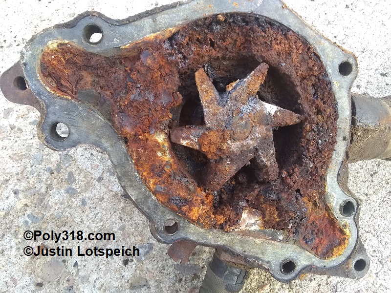
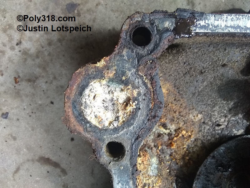
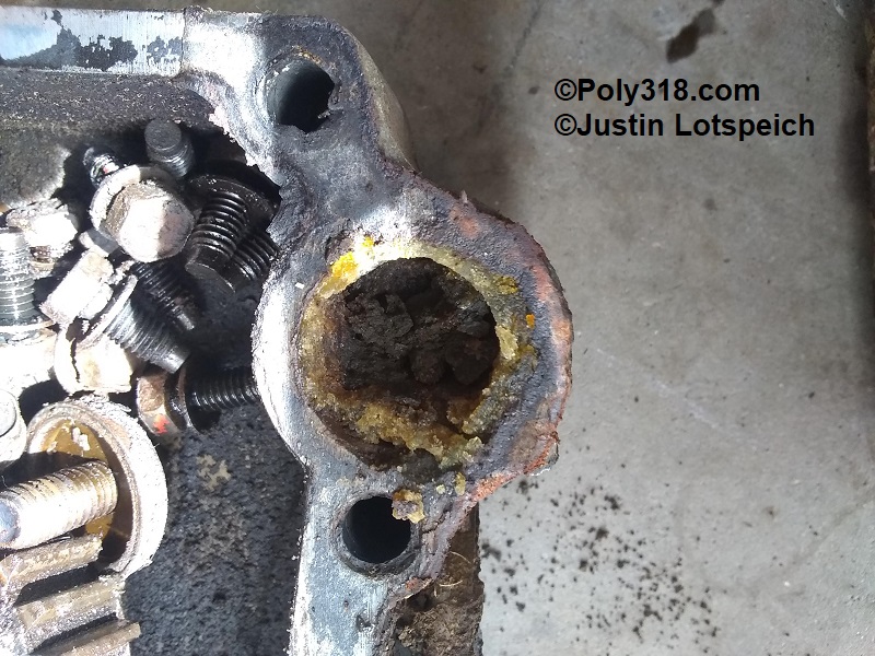
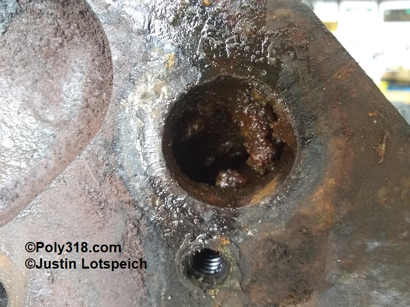
Put bluntly, never use a stop-leak product unless you are stranded in the middle of nowhere with a threat to your health or safety. A leaking radiator or heater core should be repaired properly by a shop or replaced; a leaking/corroded-through freeze plug or timing cover should be replaced; a leaking gasket (intake, head, timing cover) should be replaced. Waiting two hours for a tow truck in a safe location is a much cheaper price to pay than repairing an engine and cooling system dosed with stop-leak. Figures 5a – 5d demonstrate what happens when people use stop leak. This engine is a 1963 A318 block and water pump that I picked it up for free from a man who said,” It got up to 220° a couple times before I shut it off, and I couldn’t figure out the cause and decided to swap in an LA.” No wonder it overheated. This engine would require removal, disassembly, and few runs through power-washing and hot-tanking to clear the water jackets, which is far more expensive and time consuming than repairing the leak in the first place.
Figures