Poly 318 Carburetor Selection
and Tuning
Introduction
In this article, I discuss sizing and tuning Carter, Edelbrock, and Holley carburetors including idle mixture, jets, metering rods, and power valve. Tuning parts such as jets, rods, springs, and power valves are available through many retailers including Summit Racing, Jegs, and Mike’s Carburetor Parts.
Sizing Carburetor CFM
There is much misinformation on the internet about properly sizing carburetors. Many people see common carbs such as a 500, 650, 750, and Thermoquad (which start at around 800 cfm) mentioned on forums or in parts advertisements and throw recommendations around without knowing the engine specifics. Engine specifics and basic algebra are necessary for sizing the carburetor cfm followed by properly dialing in the jetting. Without doing so, people are likely killing port velocity, throwing away performance, carboning up their engines, and spending too much money on the carburetor and fuel since most people over-carburate rather than under-carburate.
The equation to calculate how much cfm carburetor the engine requires depends on multiple variables:
- Engine displacement in inches
- Maximum RPM/Redline per the cam profile
- Volumetric Efficiency (VE as a decimal percentage)
- Street VE = approx. 85%
- Street/Strip VE = approx. 100%
- Full Race VE = approx. 110%
The equation is CFM = (c.i.d. x rpm x VE) / 3456
For example, a bone-stock A318 with a redline of 4,400 rpm for street use would have an equation of CFM = (318 x 4400 x 0.85) / 3456 = 344 . This engine will require a maximum of 344 cfm even though a slew of people on forums would swear the engine would run best with a 650 cfm. It is wise to go up to the next available size carburetor for wiggle room, so a 400 cfm would likely be ideal for this example. A 500 cfm would be another option, although the engine will lose lower-rpm performance for high-rpm gains.
What if we hop up this stocker with a hotter cam and plan on making a couple occasional passes at the track? The camshaft raises the redline to 6,000 rpm, and we will assume a 100% VE. CFM = (318 x 6000 x 1.0) / 3456 = 552. 600 cfm, so a 600 cfm or 650 cfm would work well on this engine.
For one more example, let us assume a 390 stroker with a redline of 6,500 rpm in a street/strip car, keeping the VE at 100%. CFM = (390 x 6500 x 1.0) / 3456 = 734. In this case, 750 cfm would work well. Bump the VE to full-race 110%, and 800 cfm or 850 cfm would work well.
“But, what about multi-carb setups!” one retorts after reading my bit about calculating CFM. How could a A318 that from the equation above needs 552 cfm run well with two 500 cfm carburetors for a total of 1,000 cfm? Jetting is the answer, and in this example detuning the two 500 cfm carburetors to lean them out. Read the section on jetting below for more details, but idle air-fuel mixture is an important first step before messing with jetting. See the Carter AFB List for CFM options and model numbers.
Setting Idle Air-fuel Mixture (Carter, Edelbrock, Holley)
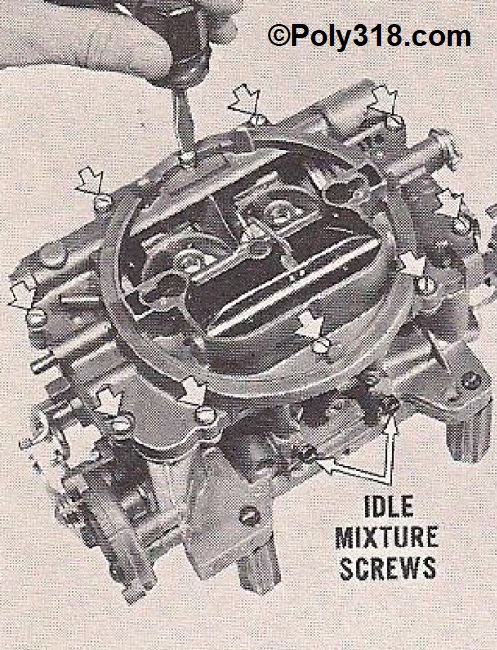
The idle air-fuel mixture is an important and easy adjustment. Some people on forums mistakenly believe that adjusting the idle air-fuel mixture adjusts the carburetor’s jetting, but this circuit only functions at idle and is overtaken by the accelerator pump and primary circuit once the throttle opens. There are multiple methods to set idle air-fuel, but the most reliable and what I think is also the easiest is using a vacuum gauge and tachometer. In this case, I use my timing gun that has an integrated tach so I can perform the adjustments without needing a second person managing the tach in the cabin. The goal is to find the highest vacuum reading with all screws adjusted at the same amount of turn out from fully turned in/seated.
- WARNING: never force the mixture screw tight. Once feeling the screw lightly bottom out/seat, stop turning. Tightening the screw is absolutely unnecessary and can carve a groove in the needle, deform the seat, and can also strip the threads.
- Note: Some carburetor models have backwards idle adjustment where turning the screw clockwise fattens the mixture and counterclockwise leans out the mixture.
- With the engine off, remove the air cleaner, attach the vacuum gauge to manifold vacuum, and set up the tach. Ensure all hoses/chords are clear of exhaust and fans/blades.
- If the engine has been running decently, use a small screwdriver to gently turn in one mixture screw until it just seats, counting the rotations. Think of a clock where 1:30 is 1/8, 3:00 is 1/4, 6:00 is 1/2, etc. Record this number and perform the process on all mixture screws. They all need to match, so if a screw is 1 turn out and another is 1.5 turns out, split the difference and set both at 1.25 turns out.
- Start the engine and bring up to running temperature ensuring the choke is wide open.
- Ensure that the hot idle speed is set for what the cam requires to idle well in gear.
- Record the vacuum reading.
- Turn one mixture screw 1/8 turn in to lean the mixture (most carbs are clockwise equals lean and counterclockwise equals rich, so reverse if the carb is the opposite). If vacuum increases, move to the other mixture screws, turning each the same amount one at a time watching the vacuum gauge. If the vacuum decreases on the first screw when turning it in (lean), turn the screw back out 1/8 to where it started and then another 1/8 out to fatten the mixture. Move to the other screws backing them off 1/8 turn to match this first screw, watching the vacuum gauge during each adjustment.
- Very Important Note: After adjusting each screw, reset the idle speed back to the original rpm since idle speed impacts the mixture adjustments.
- Continue this process by 1/8 turns until the vacuum decreases on one of the screws. Once the vacuum decreases, turn the screws the opposite way 1/16 – 1/8 turn each until finding the sweet spot where vacuum is highest.
- Once the engine reaches the highest vacuum at the set idle speed with all screws adjusted the same number of turns out from bottom, the idle air-fuel mixture is set.
- Note: aggressive cams that require higher idle speeds can sometimes idle with the throttle plates open far enough to uncover the idle transfer slot machined into the base plate, causing issues with adjusting the idle air-fuel mixture. Drilling a hole in a specific place in the throttle plates (butterflies) and tuning it by drilling larger increments resolves the problem, but that is another tech article for another time.
Primary Jet Tuning (Carter, Edelbrock, Holley)
Most people I have ever met in person and online simply buy a random-sized carburetor their buddy or a speed shop told them was the trick setup, pull it out of the box, bolt it on, and think they are done. Tuning jetting takes time and patience, but it is necessary for optimal performance, especially with multiple carburetors.
For the old-school method (i.e. non-digital meter), here’s how I dial in the carburetor primary jetting:
For carburetors with power valves (e.g. Holley 4150/4160 series), I need to tune the power valve first. The power valve is rated for what inches of mercury (inHg) it will open at and stay open below. For example, a 6.5 inHg power valve means the valve will stay open until the vacuum reaches 6.6 inHg or above. The power valve is meant to dump fuel into the mixture when the throttle is opened hard and vacuum plummets before once again rising and stabilizing at which point the primaries and secondaries will be at work and no longer require the power valve dump. The issue is if the engine has an aggressive cam with a lot of overlap or the engine runs in high elevations with lower atmospheric pressure, the engine may idle in gear at a vacuum below the power valve rating to where the valve is open at idle creating an extremely rich idle mixture all the time. If I do not dial in the power valve first, the spark plugs during the primary jetting test will always read extremely rich.
Power Valve Tuning (Holley/Quick Fuel)
- I hook up a vacuum gauge to manifold vacuum where I can read the gauge (or have someone read the gauge) while I have the car in gear.
- Start the engine in park/neutral and bring it up to running temperature.
- Ensure proper idle speed is set depending on the cam. For vehicles with A/C, I make sure the compressor is running when setting idle.
- For a manual vehicle, I record the lowest vacuum at hot idle in neutral and shut off the engine. For an automatic vehicle, I ensure no one is standing near the vehicle, apply the brakes, and place the transmission in gear. I record the lowest vacuum at idle, place the transmission in park, and shut off the engine.
- I find a power valve that is one size lower than the vacuum recorded. For example, most Holley 4150/4160 come standard with a 6.5 inHg power valve. If I recorded the lowest idle vacuum at 6.5 inHg, I need a 6.0 power valve to stop the valve from opening at idle. If I recorded idle vacuum at 6.25 inHg, I need a 5.5 power valve to account for any dips in idle speed during idle. These levels may seem very low for sea-level and less-aggressive cam folk, but I currently have an engine with a lot of cam overlap, and at 5,600’ elevation it idles in gear at 5.9 inHg, therefore needing a 5.5 power valve.
- To replace the power valve, follow the instruction below for changing Holley jets adding the step of removing the metering block #123 (see Figure 5 below) where you can then get to the power valve.
- Note for performance racing engines: The above is a baseline for minimum power valve pressure, but there are other steps to take for race engines including running the vacuum gauge into the cabin to where we can read it while driving to further dial in the power valve. I’ll write another tech segment for this procedure when I get the time.
First Spark Plug Test (all carburetors)
1. Start the engine in park/neutral and bring it up to running temperature. Shut it off.
2. After the engine cools to where I can safely remove the spark plugs with heat gloves on, I replace all spark plugs with new ones properly gapped.
- Note: If I am in a situation where I do not have a safe stretch of road immediately near me where I can perform the test, I will drive out to a safe area and change the plugs there.
3. I start the engine and immediately drive on a safe stretch of road I already have mapped out for 1/4 to 1/2 mile keeping the rpms low and steady enough to not open the secondaries (if applicable). Cruising at around 35 mph is typically a good speed. Do not let the secondaries open at all by blipping or mashing the throttle.
- Note: The reason I warmed up the engine prior to changing the plugs is so the engine will more quickly warm up near or to running temperature for this test.
4. After cruising for 1/4 to 1/2 mile, I place the transmission in neutral, shut off the engine, and coast off the road to a safe parking spot. Once stopped, place the transmission in park or set the brake.
5. After the engine cools to where I can safely remove spark plugs with a heat glove, I pull at least two plugs from each cylinder bank and read them (see Figure 5 below). If the plugs read lean, I need to richen the primary jets and/or metering rods; if they read rich, I need to lean out the primary jetting.
6. To replace jets, I drive back to where I am working on the engine without opening the secondaries. If this isn’t possible, I swap the new plugs for the old ones to drive back or plan on media blasting the plugs.
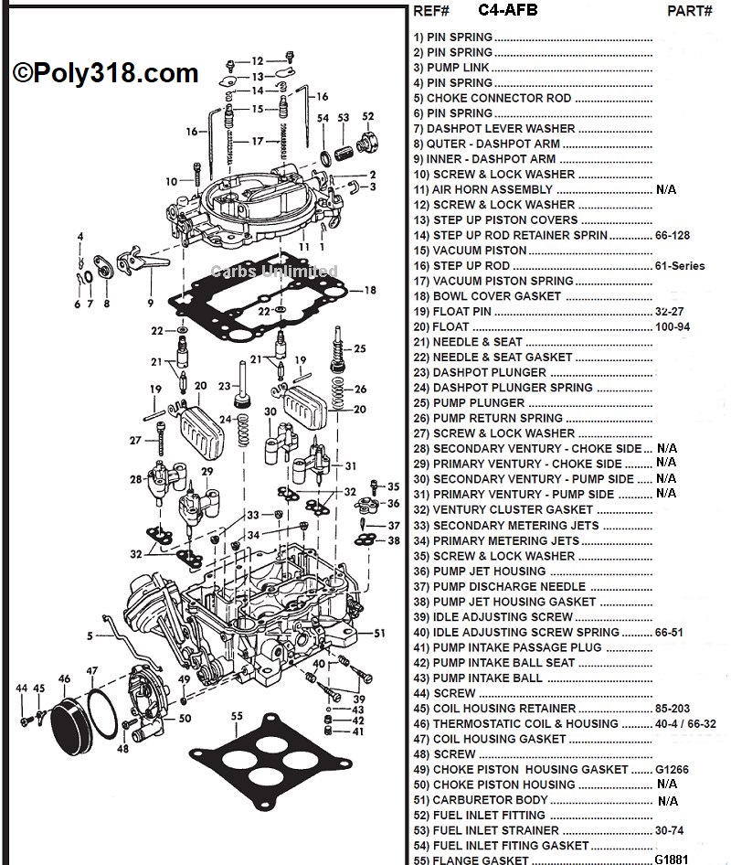
Adjusting Jetting (Carter AFB/AVS and Edelbrock AVS)
Notes:
- Carter/Edelbrock jets are numbered where the higher the number, the richer the jet.
- Metering rods are numbered where the higher the number, the leaner the mixture since the larger diameter rod blocks more of the jet’s orifice.
- If leaning out the jetting by installing larger metering rods gets to the point where they block the jet orifice, a larger jet #34 must be installed (Figure 1). Jet changes requires removing the air-horn assembly #11, described below.
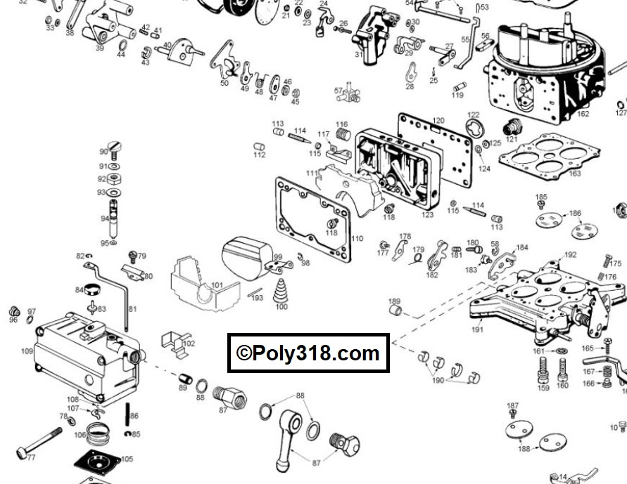
Metering Rod Change
- Remove the two step-up piston screws #12 and covers #13. Before removing the screw, apply slight pressure on the cover to hold down the piston since it is spring loaded and can pop up.
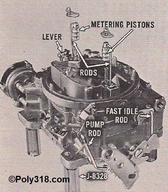
- Gently remove one piston-rod assembly (#s 14, 15, 16, 17) at a time and place them on a clean paper towel (Figure 2).
- Gently unhook the retainer spring #14 and rod #16, using a finger to hold the retainer spring against the piston while removing the metering rod.
- Insert the new rod and secure the retainer spring.
- Verifying that the piston-rod assembly is clean of debris, insert the assembly back into the carburetor and replace the covers. Be careful not to over-tighten the cover screw or round-off the head.
Jet Change
- Disconnect the choke rod (if applicable), accelerator pump lever #5, accelerator pump link #3, and the fuel line. Remove all air horn screws, including the one down in the well (Figure 3).
- Remove the metering piston-rod assemblies as described in the previous steps.
- Gently use a flathead screwdriver between the cover and body to pry the cover up about 3/8″ evenly around being careful not to gouge the metal.
- Using the screwdriver and/or fingers, pull the gasket up to where it will come off with the air horn. WARNING: If the gasket remains on the body and you pull up on the air horn, the floats will be trapped in the body and can bend.
- Gently, evenly lift straight up on the air horn to remove it being careful not to bend the venturi #31 tubes. Set it upside-down on a clean paper towel.
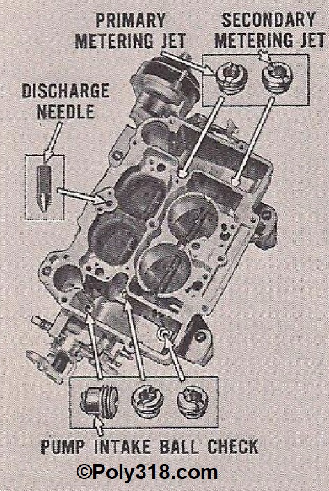
- Using a clean, properly fitting flathead screwdriver, remove the primary jets #34 turning counterclockwise (Figure 4). Use a very clean pair of needle-nose pliers or claw to extract the jets from the fuel.
- Set the new jets into the holes using the needle-nose pliers or claw and snug them down being careful not to cross-thread, overtighten, or round off the slots.
- Reinstall the air horn ensuring the gasket, venturies #30 and #31, and accelerator pump plunger #25 align. Tighten the screws in a three-step sequence starting in the middle and working out in an “X” pattern until you feel the gasket seat. Do not overtighten the screws or round off the heads since doing so can warp the air horn.
- Reinstall the accelerator link, choke rod, and fuel line.
Adjusting Jetting (Holley 4150/4160)
Note: Holley jets are numbered where the higher the number the richer the jet.
- Place a rag and a short container under the front float bowl.
- Remove a lower float bowl screw #77 so fuel drains into the container. Remove the container (Figure 5).
- Remove the fuel line(s) and remaining float bowl screws, and carefully remove the float bowl #109 trying not to tear the gasket. If the gasket tears/deforms, replace it. Using the blue gaskets help with pulling the float bowl and metering block multiple times. Note: If the metering block #123 is very secure, leave it alone and change the jets on the carburetor; if the metering block is loose, gently remove it trying not to tear the gasket to work at the bench.
- Using either a Holley jet screwdriver or a snug-fitting, wide screwdriver, remove the two jets #118 turning counterclockwise.
- Install the new jets, snugging them down but not overtightening or rounding off the slots.
- Replace the float bowl, guiding the accelerator pump arm into place. Tighten the bowl screws in a three-step sequence in an “X” pattern until you feel the gasket seat. Do not overtighten. Replace the fuel line.
Retesting Spark Plugs after Jetting Change
After the jetting change on any type of carburetor, repeat the spark-plug testing process and keep adjusting jetting until the plugs read optimally. If the plugs aren’t sooted up, I reuse them for the tests. If they are sooted, I media blast them to clean them to save from having to purchase a new set. Once the four plugs (two from each bank) read ideal, I pull all plugs to read them all.
Conclusion
Now that we have covered tuning primary jetting, the idea of running two 500 cfm carburetors on an engine that requires only 552 cfm should make sense. If one bolts on two aftermarket 500 cfm carburetors out of the box, the engine will in most cases run rich. By detuning the carburetors’ jetting, one can end up with carburetors that flow a lot of cfm but are providing the engine with optimal fuel.
Secondary tuning is crucial as well, so I will work on that addition to this article. I also want to discuss setting up a digital air/fuel meter system to dial in both primary and secondary circuits, which is a superior way to go especially for multi-carb setups.
Figures