Carter AFB AVS Rebuilding and Aluminum Cleaning
Introduction
The factory service manual is a great resource when rebuilding Carter carburetors, but there are some areas and cleaning tricks and pointers not covered in the manuals. I have written this extensive walkthrough to fill in these gaps. Particularly concerning are some of the cleaning techniques people on forums recommend, from sand-blasting to hydrochloric (muriatic) acid, which are both terrible ideas that I discuss below. This technical article focuses on Carter AFB and to a degree AVS carburetors, but much of the general content is applicable to other models and makes. For a list of Mopar Carter AFB carburetors and their CFM information, see my carb data page. Rebuild parts such as jets, rods, springs, and gasket kits are available through many retailers including Summit Racing, Jegs, and Mike’s Carburetor Parts.
Carburetor Disassembly
It is wise to keep all parts and gaskets removed from the carburetor until after rebuilding for potential comparisons and spares. Keep an organized workbench with three containers to store medium/large parts, small parts, and gaskets/likely throw-away parts.
- Photograph the carburetor carefully to ensure you understand how it goes together, especially the linkage and springs. Note: never trust how the linkage is setup since I have come across plenty of carburetors with incorrectly installed linkage, gaskets, etc.
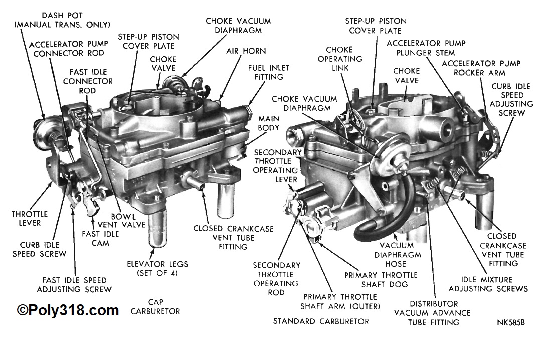
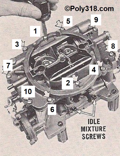
- Remove the choke linkage (if applicable), fast-idle rod, accelerator pump connector rod, accelerator pump pivot screw, accelerator pump lever and “S” link, and the fuel inlet fitting (Figure 1). Note: a quality rebuild kit will come with new spring pins for linkage rods, but it is wise to save the old one as spares. Rebuild kits do not include a new accelerator pump “S” link or fuel-inlet strainer.
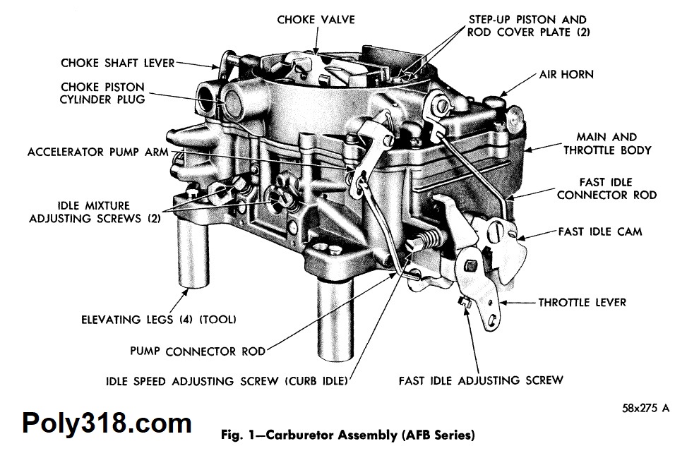
- Remove the fast-idle cam and secondary lockout dog (Figure 2).
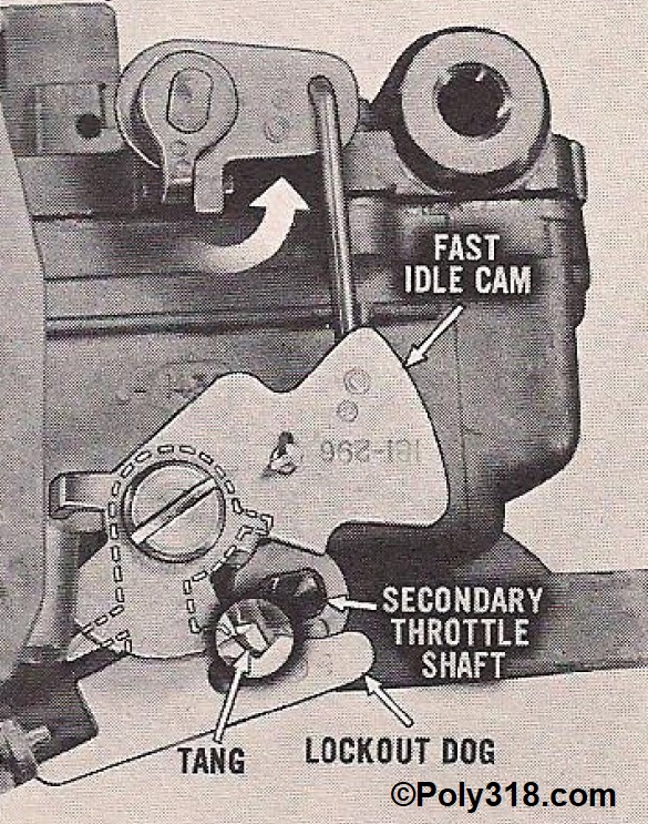
- Loosen the metering rod cover screw and swing the cover out to expose the metering rod assembly (Figure 3). Note: the assembly is spring-loaded, so be ready with a finger to stop it from popping up. Remove the metering rod assembly as one unit. Sometimes the step-up piston is stuck, so pushing down on it with a finger or gently wrapping on it with a wooden dowel and hammer usually loosens it. For stubborn assemblies, shoot penetrating oil into the well and leave it to soak in. Gently lifting up on the metering rod with needle-nose pliers is acceptable, but place the jaws directly over the vertical rod where it bends so the horizontal part doesn’t bend. After the assembly is removed, remove the spring with pliers. Note: not all rebuild kits come with new springs, so great care should be taken to not stretch/distort the old springs if reusing them. I recommend replacing the step-up piston spring when rebuilding, however.
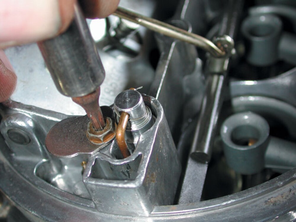
- Remove the idle mixture screws (Figure 4). If you feel any resistance turning the screws counterclockwise, use penetrating oil and then torch heat to assist in removing them without stripping the body threads.
- Following the sequence in Figure 4, remove the air horn screws noting that the longest goes in the center rear, second longest in the center front, and the shortest for the rest.
- Using a plastic pry bar, gently pry up in the corners between the air horn and body to break the gasket seal, but do not lift the air horn.
- Warning: Do not simply yank up on the air horn to remove it. If the air horn gasket sticks to the body, the floats will be trapped in the bowl. Forcing up on the cover will bend the float-drop limiting tab, possibly the float arm, and can collapse the float end. Instead of yanking up on the air horn, lift it 1/4″ off the base, and use fingers and a screwdriver/razor blade to lift the gasket off the body and up onto the air horn. For stubborn gaskets, insert an exacto razor to cut the gasket away from the body. Once the gasket is free to move up with the air horn, pinch the gasket to the air horn and gently lift straight up. If you feel resistance, stop and assess the source before proceeding.
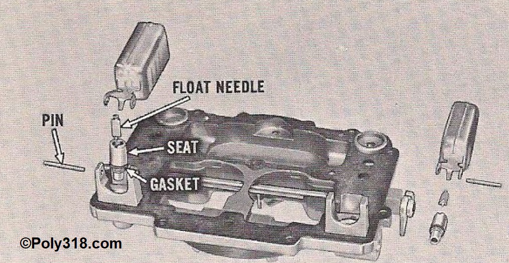
- With the air horn flipped upside down, remove the float pin (Figure 5) and gently lift out the float. Remove the needle. If the needle includes a retaining clip, be sure to save it since not all rebuild kits include them.
- Using a wide flathead screwdriver, remove the seats turning counterclockwise. Quality rebuild kits come with new needles, seats, and seat gaskets, so these parts can go in the throw-away container.
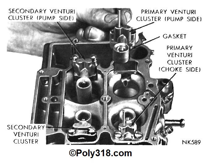
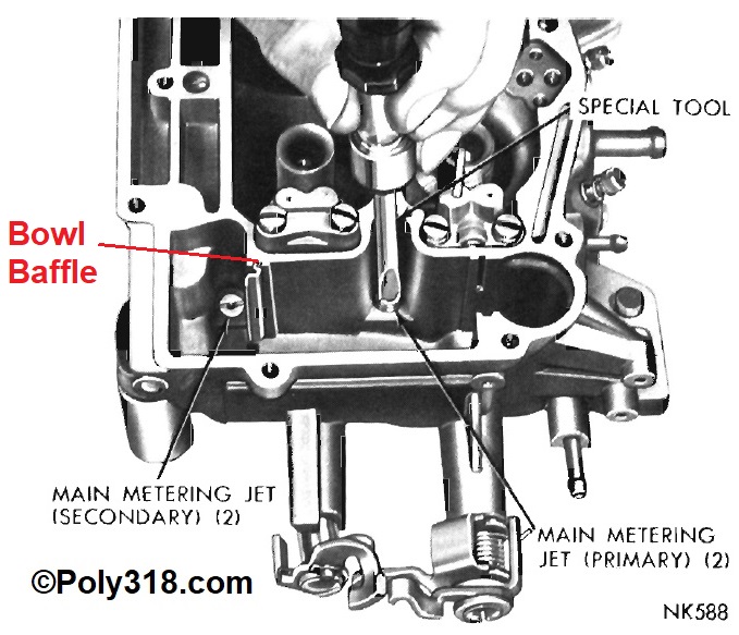
- Turning attention to the body (Figure 6), remove the accelerator pump plunger and spring, pump discharge housing, primary and secondary venturi clusters, and sheet metal baffles in the bowls. The clusters are almost always stuck to the gaskets. Pressing down and lifting up on the venturi end with fingers will usually break the seal. Sometimes, very gently prying up and pushing down on the end with a plastic pry bar is necessary. Do not damage the clusters or body, especially the venturi ends that are sensitive to aerodynamics. The primary clusters have copper tubes that go down into the body, so do not kink these during removal. The accelerator pump assembly and return spring should be replaced, so they can go in the throw-away container.
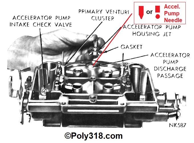
- Keeping the carburetor body close to the workbench surface, tip it over and attempt to shake out the accelerator pump discharge needle (Figure 7). Early model AFBS use a tapered weight, and later models and AVS often use a steel ball and brass weight. The needle/ball/weight will sometimes will be stuck, especially on cores that are heavily corroded or gunked up. If the needle is stuck, hold the body upside down and gently wrap on the body with a flat wooden block. If the needle remains stuck, flow compressed air through the small passage in the bottom of the accelerator-pump well, which will force air through the passage up against the needle. Warning: Hold your hand under the discharge needle bore to catch the needle since it will fire out under compressed air. For stubborn needles, shoot penetrating oil into the bore and let it soak in before working it free. Do not use sharp objects to dig out the needle that might gouge the bore walls and create binding issues.
- Using a snug-fitting flathead screwdriver, remove the accelerator-pump intake check valve (Figure 7) being careful not to round off the slots. For stubborn valves, apply penetrating oil and let it soak in. Apply heat to the aluminum housing with a propane torch if necessary. After removing the valve, use a pocket screwdriver or small drift to manually compress the ball. Inspect the spring for corrosion and proper function. Lastly, place the clean valve to your lips and blow/suck on the valve to see if it actuates and seals. Well-functioning valves can be reused after cleaning. Rebuild kits do not include a new intake valve, but they are available new if needed.
- It is a good idea to remove the primary and secondary jets (Figure 8) because the bottom of the jets have a cup machined into them that can trap sediment/residue. Use a snug-fitting flathead screwdriver turning counterclockwise. Do not round off or disform the slots. Use penetrating oil and heat as needed.
- Remove any remaining choke parts such as the pull-off canister or electric choke assembly.
General disassembly is complete. For seized throttle/choke shafts, see the last section below specifically about this issue.
Carburetor Cleaning
- Remove as many gaskets as possible without marring the aluminum. Leave stubborn gaskets, such as the venturi clusters, to soak during cleaning.
- Place the air horn on the body, and fasten it finger tight with two screws across from each other.
- I secure the carburetor to a 1’ x 2’ scrap piece of plywood using two 3” wood screws through the manifold mounting holes to secure the carburetor for pressure washing. If not pressure washing, skip this step.
- Wearing proper protective gear, spray oven cleaner liberally on the carburetor body, down in the venturis and throttle bores, and on the throttle/choke valves and linkage.
- For lightly cruddy carburetors, 10 minutes in the shade is enough time to wait. For very cruddy carburetors, weight up to 15 minutes in the shade. Wearing proper protective gear, power-wash or scrub and wash off the oven cleaner. Remove the air horn, wash out any residual oven cleaner, and remove any more gaskets that come off easily.
- Blow the body/air horn dry including all internal passages being careful of cleaning residue blowing out.
- Place a machinist’s straightedge across the perimeter of the body base where it mates to the intake and in an “x” pattern from mounting hole to diagonal mounting hole. Look for any warpage. Light warpage can be sanded out on a sheet of flat glass with wet sandpaper. Medium warpage requires resurfacing. Heavy warpage can sometimes be taken out using a torch and a jig but often requires a replacement body.
- With the air horn upside down, place a machinist’s straightedge across the perimeter of where it mates to the body and in an “x” pattern. Look for any warpage. Warpage more than half the new gasket thickness requires can sometimes be taken out using a torch and jig but often requires a replacement air horn.
- Wearing proper protective gear, soak all parts in a quality carburetor cleaner such as Berryman Chem-Dip. I use a 90°F heated ultrasonic bath that speeds up cleaning and improves the quality of cleaning internally immensely.
- After adequately soaking the parts and wearing proper protective gear, remove all remaining gaskets and scrub off any remaining soot/crud. Let the carb cleaner drip off the parts.
- Wearing proper protective gear, repeatedly dip the parts in a 2.5-gallon bucket of hot water and 1-cup of TSP.
- Immediately repeatedly dip the parts in another 5-gallon bucket of hot water to rinse off all TSP solution.
Now we’re ready to address aluminum and steel discoloration and staining.
Acid Cleaning Bare Aluminum Carburetors for Color Uniformity
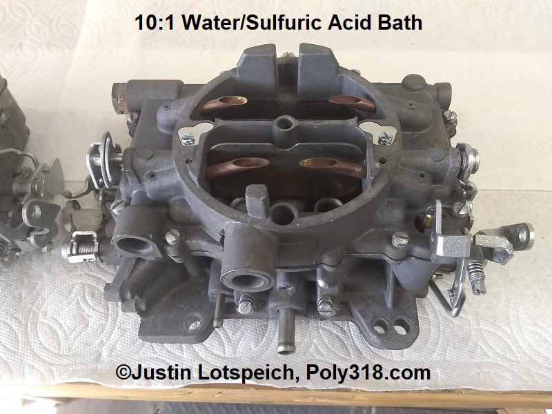
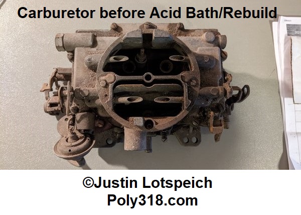
Even well-cleaned bare-aluminum carburetors are almost always discolored by oxidation, heat, chemicals, wear, etc. Do a search online, and you get all sorts of what I think are terrible ideas ranging from media blasting to soaking in hydrochloric (muriatic) acid. First, blasting media is the last thing I want near my carburetors, and it opens up the aluminum pores to where the surface will stain very quickly with oil/fuel/chemicals. Second, hydrochloric acid aggressively eats aluminum at any ratio leaving the polished accelerator pump well and venturis/throttle bores rough, and it leaves aluminum dark gray/black. These are examples of misguided cleaning options. After reading a couple peer-reviewed scholarly articles on aluminum reactions to different acids, I came upon a possible cleaning agent. Any concentration of sulfuric acid above 10% eats aluminum and steel, but a solution under 10% will clean aluminum and steel without damaging them! It also does not impact copper, brass, or bronze.My next step was to locate sulfuric acid, which I did by reading searching my local hardware store products and reading their SDS sheets. I came upon Zep brand liquid “Sulfuric Acid Drain Opener Professional Strength” (UNSPSC 47131800) which as of 2010 happens to be 90% sulfuric acid and 10% stability agents that don’t impact aluminum, copper, brass, or steel. I mixed different ratios of the drain cleaner and water and tested junk parts carburetor bodies/air horns at different lengths of soaking until I landed on the answer that gives the carburetor a new as-cast look while retaining the the machined/polished sections.Send me $100 and I’ll tell you the answer. That’s an actual response I came across multiple times from a couple supposed carburetor rebuilders on forums when people asked for advice on getting as-cast aluminum looking uniform. No need for payment here, although I would appreciate credit if you spread this process across the globe since it took me a lot of work and time to figure out.
Warning: wear protective gear including gloves, goggles, respirator, and clothing that covers your body. Always add the acid to the water and not the other way around since adding water to acid can create a boil-over/explosion. This 90% sulfuric acid and reduced solution are extremely corrosive with a single speck burning skin and fumes burning the respiratory system.
Place 1.75 gallons (six quarts) of cool water into a 5-gallon plastic bucket. Measure 19 ounces of the drain cleaner into a plastic or glass container being careful not to splash it. Lower the container into the water before tipping it over to mix in the acid without splashing. Use the container to gently mix the solution. This mixture comes out to slightly weaker than 10:1. Rinse off the gloves in fresh water.
Parts to be acid dipped:
- Carb body including throttle shafts/valves
- Air horn including choke shaft/valve
- Venturi clusters
- Corroded choke/throttle/accelerator pump levers/rods (they will need painting or replating after)
- Exterior screws (they will need painting or replating after)
- Steel fuel inlet adapter
- Fill two separate plastic buckets with 4 gallons of cool water and place them directly adjacent the acid solution in a row.
- Gently lower the carburetor body into the acid solution and roll it to remove any air pockets. Set it on the bottom of the bucket and rinse your gloves. Set a timer for 3.5 minutes.
- At 3.5 minutes, carefully lift the body out of the acid tipping it over low in the bucket to pour out the solution without splashing.
- Immediately and gently lower the body into the first bucket of water and swirl/roll it to rinse out the acid solution.
- Remove the body and lower it into the last bucket of water, swirling/rolling it around for a final rinse.
- Immediately blow the body dry with compressed air making sure to blow out all passages and the throttle shaft bores.
- Follow the same procedure for the air horn and above listed parts. I use a plastic strainer bucket for the small parts. The steel small parts can be left in for up to 20 minutes if they are heavily corroded, but don’t expect all rust to be removed using this acid bath.
Carburetor Assembly
Carburetor assembly requires a very clean workbench and organized space for all the clean parts and rebuild kit parts. I use a large aluminum baking sheet or clean drip pan.
- Focusing on the body (Figure 7), install the cleaned or new accelerator pump intake valve snugging it down but not overtightening or rounding off the slots.
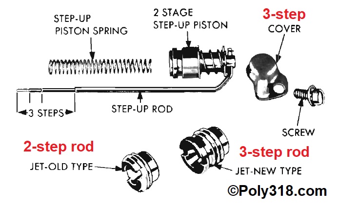
- Install the primary and secondary jets (Figure 8) snugging them down but not overtightening or rounding off the slots. Note: Now is the time to make any jetting adjustments for elevation, engine displacement/use purpose, or multi-carb setups. Two-step metering rods require the shorter jet style, whereas three-step rods require the taller jet style (Figure 15).
- After inspecting for debris, gently drop in the new accelerator pump discharge needle (Figure 7). If using a ball and weight, drop in the ball followed by the brass weight. Note: Do not reuse the brass needle or steel ball. You may reuse the brass weight if it is free of corrosion and moves smoothly up and down inside the bore.
- Install the proper discharge gasket and pump discharge housing (Figure 7). Gently and evenly tighten the screws in a three-step sequence until you feel the gasket seat, which is usually when you feel firm resistance gripping the end of the screwdriver with two fingers and thumb. Important: It is easy to confuse the discharge housing screws for the choke pull-off mounting screws, but they are different. The choke pull-off screws usually have self-tapping threads.
- Install the sheet metal bowl baffles with the kickout facing the rear of the carburetor (Figure 8).
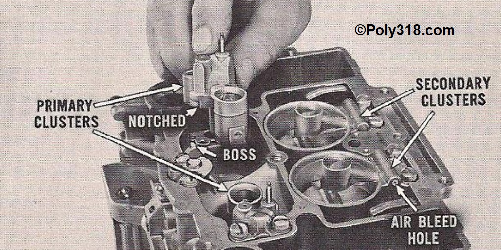
- Install the proper primary and secondary cluster gaskets and primary and secondary clusters (Figure 8). Note: The primary clusters have a notch on the bottom corner that aligns them into the body, but the small vent hole in the aluminum housing faces forward. On earlier AFBs with similar secondary clusters, the small vent hole faces outward. For later AFBs/AVSs with large secondary clusters (Figure 9), the side air-bleed holes face outward. Gently and evenly tighten the screws in a three-step sequence until you feel the gasket seat, which is usually when you feel firm resistance gripping the end of the screwdriver with two fingers and thumb.
- Drop in the new accelerator pump return spring, which is the thinner-gauge, long spring compared to the stiffer and narrower accelerator plunger delayer spring. Ensure it registers down in the groove.
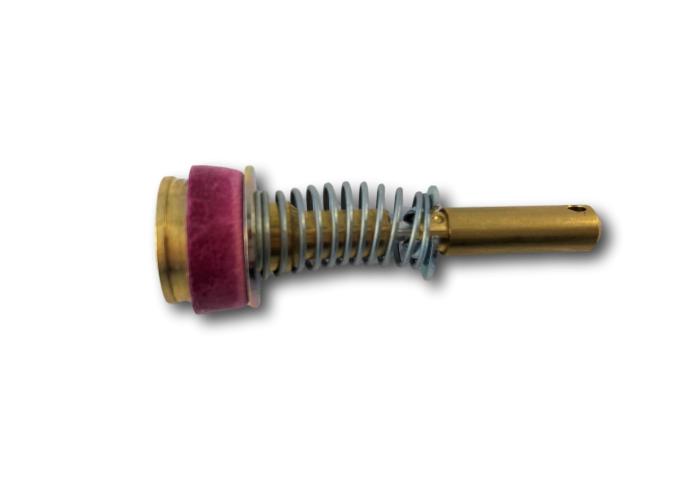
- Rebuild kits with quality brass ethanol-resistant accelerator pump plungers often have the plunger assembly disassembled. The plunger delayer spring slides onto the shaft and registers around the piston. Compress the spring with your fingers and slide the retainer around the shaft sideways with the bulge facing the spring so the spring registers around it (Figure 10). Wipe/blow off the seal to ensure it has no lint/debris, and lower the assembly into the well ensuring the return spring registers in the center of the plunger.
- Turning attention to the air horn (Figure 5), place the air horn upside down. Thread the seat gaskets onto the seats and install the seats. Tighten until you feel the gasket seat. After tightening, blow out the fuel intake passage and seats with compressed air to remove any shavings from assembly.
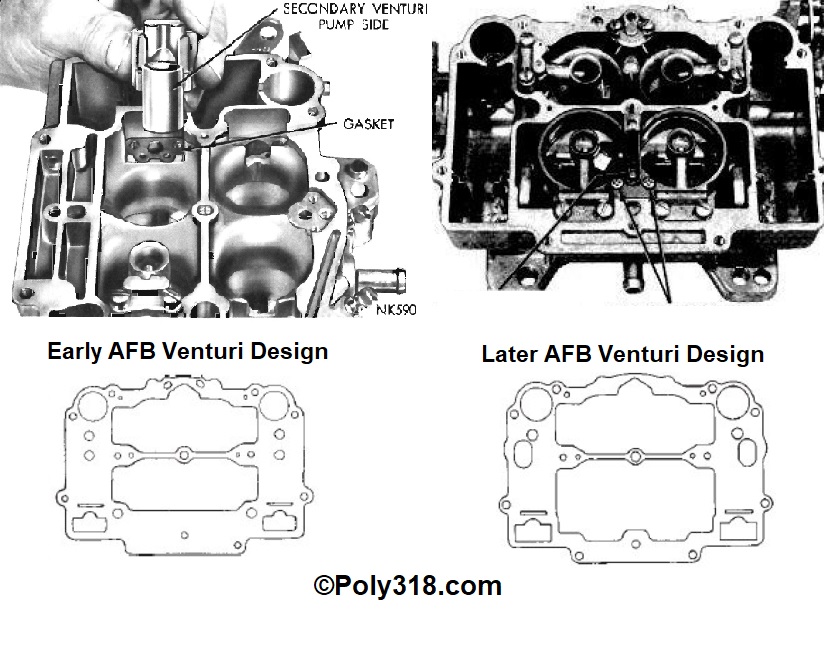
- Install the proper air-horn gasket being careful not to tear it around the float towers, float baffles, and seats (Figure 5). Using a clean screwdriver or plastic prybar to guide the gasket down helps here. Important: there are two different AFB AVS air horn gasket designs that must be matched properly to the carburetor model (Figure 11). Early models with similar primary and secondary venturi clusters take the gasket with the wide rear section; later models with large secondary venturis take the gasket with a narrow rear section. Using a narrow late-model gasket on an early model carburetor will leak fuel, and using an early model wide gasket on a late-model carburetor will distort the gasket up over the air bleed channels and cause a pocket of turbulent air in the venturi. Different models take different gaskets within these two designs including part numbers G1325, G376, G585, G593, and G339; verify the correct gasket for the carb model.
- Testing brass floats: Boil a quart of water and remove it from the heat. Grip the float by the flat of the lever with needle-nose pliers and submerge the float into the hot water. Watch for 30 seconds for any bubbles exiting the float. If no bubbles appear, the float is good; if bubbles appear, re-solder or replace the float.
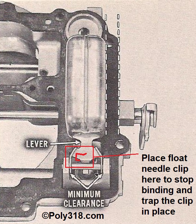
- Without installing the float needles, install the floats and pins. Verify that the float has enough clearance to easily swing at the pivot point (Figure 12). Bend the ears as necessary. Verify the float rests parallel with the air horn side and correct as necessary by very gently bending the float sideways while supporting the lever with your fingers, which will bend the float wall at the lever connection. Remove the float pins and floats.
- If using float needle clips, snap them onto the needles. Not all AFB/AVS models use the needle clips, and they aren’t mandatory. Their purpose is to pull the needles off the seats in the event they ever stick closed. I modified Figure 12 to show where to place the clip since placing the clip from the float side can create binding in the needle. This pictured position also traps the clip between the stop tang and the pivot ear.
- Inspect the needle tip for debris, gently lower the needle/float into the seat, and install the pin. Gently lift up and set down the float checking that there is no binding in the needle. Warning: From this point forward, never apply more pressure to the needles than the weight of the floats with the air horn upside down. The needle tips are very susceptible to damage and leaking with excessive force, so use care to guide the floats down onto the needles gently rather than letting them fall down hard.
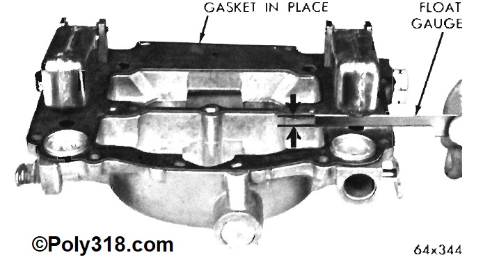
- With the air horn upside down, measure the float level by sliding a clean drill bit between the gasket and float at the front of the float just before it begins rounding vertical, or use a ruler at this same point measuring to the bottom of the float seam (Figure 13). Most AFBs call for a 7/32” float level, but follow the carb model’s spec from the kit/service manual. If adjustment is needed, lift the float up slightly to lift the needle off the seat. Using a pair of needle-nose pliers, bend the lever at the illustrated spot. Do not apply any pressure to the needle, and remove the float to bend it if you fear you might apply any pressure to the needle.
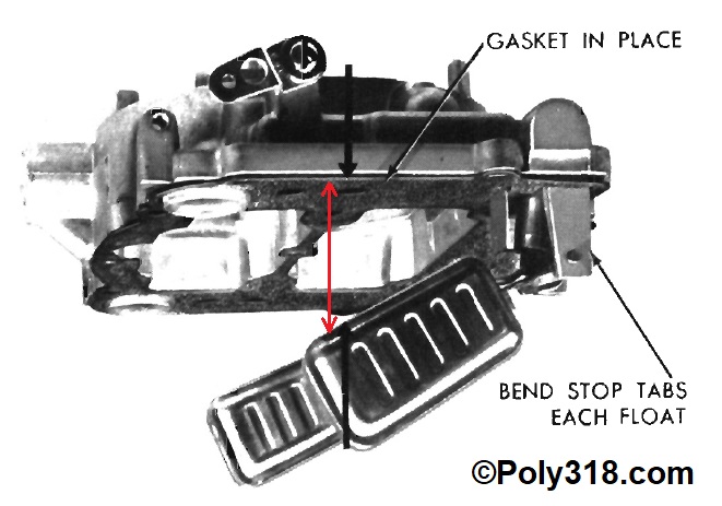
- Once the float level is set, set the float drop (Figure 14). Manuals demonstrate this procedure with the air horn held in the air right side up, but it is easier for the initial adjustment with the air horn upside down. Gently lift the float with one hand until the stop tab just contacts the seat. Using a ruler or Vernier caliper, measure the height at the same spot you measured the float level. Most AFBs call for 3/4″ float drop, but follow the carb model’s spec from the kit/service manual. If adjustment is needed, remove the pin and float and separate the needle being careful to note which needle goes with which seat since they are now matched. Using needle-nose pliers and supporting the float lever with your fingers to ensure it does not bend and change the float level, gently bend the stop tab to increase or decrease the float drop. Note: it does not take visibly noticeable bending to move this measurement 1/4″, so go by feel in very small adjustments.
- Reinstall the float and pin without the needle. Remeasure and adjust the stop tab as needed. Once the gap is set, gently rotate the air horn right side up guiding the float down to gently drop, pinch the gasket tight to the air horn with your fingers, and remeasure the drop to confirm it is still within spec. Remove the pin and float, inspect the needle for debris, and reinstall the needle, float, and pin making sure to install the needles in their matched seats. Remeasure both the float level and drop (with the air horn right side up) one last time to confirm nothing changed during adjustment and assembly.
- Inspect the body interior for any debris. Position the air horn directly over the body. Guide the accelerator-pump plunger and venturi cluster vent tubes into their air-horn holes, and slowly lower the air horn onto the body. It often requires gently shifting the air horn side to side and back and forth to align everything and get it to set down, but do not bend the venturi cluster vent tubes or bowls.
- After the air horn is completely and evenly resting on the body, follow Figure 4 to gently and evenly tighten the screws in a three-step sequence until you feel the gasket seat, which is usually when you feel firm resistance gripping the end of the screwdriver with two fingers and thumb. Overtightening the air horn can warp it and cause leaks.
- Inspect the idle-mixture screw needles for damage such as wear grooves. If grooves are present, replace the screws. Install the springs over the screws, inspect the needles for debris, and install the screws. Turn the needles by hand until they just bottom out. Back each off 1-1/2 turns, which will allow the engine to run until the idle mixture is properly set by vacuum. See my carburetor tuning technical article for setting idle mixture.
- Install the fuel inlet adapter.
- Install the metering rod assembly covers onto the air horn keeping them loose and swung out (Figure 3).
- Assemble the metering rods (Figure 15). Place the retaining clip atop the step-up piston, hold down one end with a finger, and insert the metering rod through the piston. Press down on the retainer and guide it into the rod groove. Inspect the rods and pistons for debris.
- Drop the piston spring into the bore ensuring it registers in the center. Guide the metering rod and piston into their bores and the spring into the piston. Jostling the piston, compress it into the bore and install the cover plate. Gently tighten the screws to where you feel them seat. Do not overtighten since these screws are easy to strip.
- Install the accelerator pump “S” link and lever, tightening the pivot bolt until it seats (Figure 16). Ensure the “S” link is positioned with the open end facing out on the lever. Install the connector rod. Note: some levers have multiple holes like the figure while others have one hole. On levers with three holes, the hole farthest out is the lightest fuel shot with the hole farthest in the heaviest shot. Install the rod in the center hole for baseline testing.
- Working away from the assembly table, take a single-cut file and clean up the steps on the fast-idle cam so they have crisp edges and smooth ramps. Blow off the cam when finished. Install the secondary lockout dog, fast-idle cam, and screw (Figure 2). Tighten the screw until it seats.
- Install the fast idle rod and the choke rod (Figure 1).
Fine Carburetor Adjustments
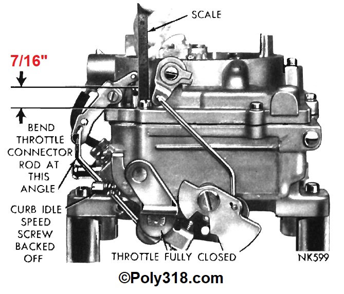
- Accelerator Pump Adjustment (Figure 16): With the idle-speed screw backed off all the way, the primary throttle valve closed, and the choke valve open, measure the distance from the air horn top to the top of the accelerator pump plunger. Bend the connector rod as shown to adjust this clearance to 7/16”. Slowly open the throttle wide and let it slowly close on its own while inspecting the “S” link and primary throttle valves to ensure the link does not bind and hold open the valves. Remove and bend the “S” link to correct any bind.
- Choke Valve and Vacuum Kick Adjustment: Follow the kit/service manual spec and instructions for the carburetor model and choke type. Because of the many different choke configurations, I don’t detail the processes here.
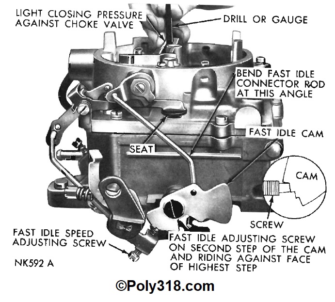
- Fast Idle Cam Adjustment (Figure 17): With the fast-idle screw resting on the second highest step of the fast-idle cam, lightly close the choke with one hand. Adjust the gap between the choke valve and air horn wall to 5/32” (#50 drill bit) by bending the fast-idle rod as shown. If adjustment room runs out, the cam tang that hits the body lug may need bending.
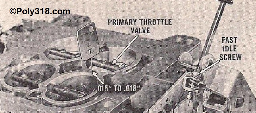
- Fast Idle RPM Adjustment (Figure 18): Close the coke valve and set the fast-idle screw onto the highest step of the cam. Flip over the carburetor. Adjust the fast-idle screw until the primary throttle valves open between .015” – .018.” The fast idle will be later adjusted cold with the engine running, but this adjustment puts it close to 1,600 – 1,800 rpm.
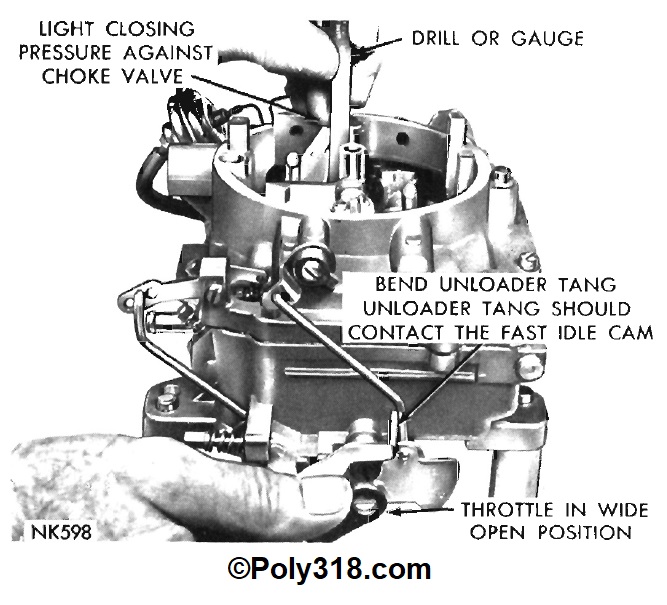
- Choke Unloader Adjustment (Figure 19): Open the primary throttle wide open. Lightly press the choke valve closed and measure the gap between the valve and the air horn wall. Bend the unloader tang to adjust to the kit/service manual spec for the carburetor model, which is usually 3/8”.
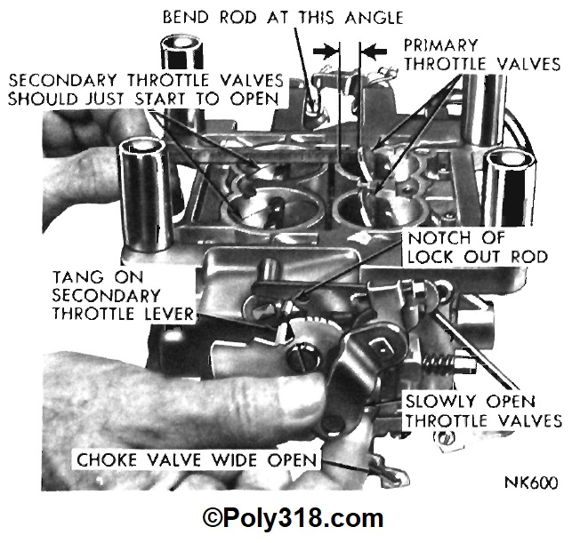
- Secondary Throttle Valve Adjustment (Figure 20): With the choke blocked open, open the primary throttle until you measure 21/64” between the lower edge of the primary valve and the bore wall. At this point, the secondaries should begin opening. Bend the pictured secondary throttle operating rod (the small dogleg rod on the right) to adjust.
- Secondary Closing Shoe Adjustment:
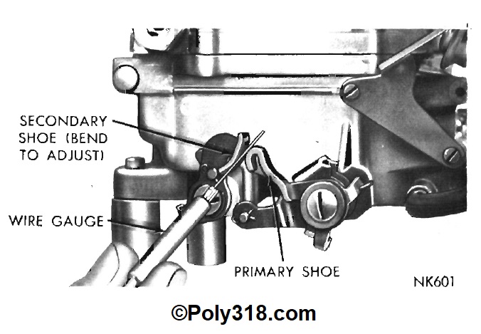
- With the choke valve and throttle closed, check for .020” clearance between the primary throttle arm and secondary positive closing shoe (Figure 21). Bend the shoe to adjust.
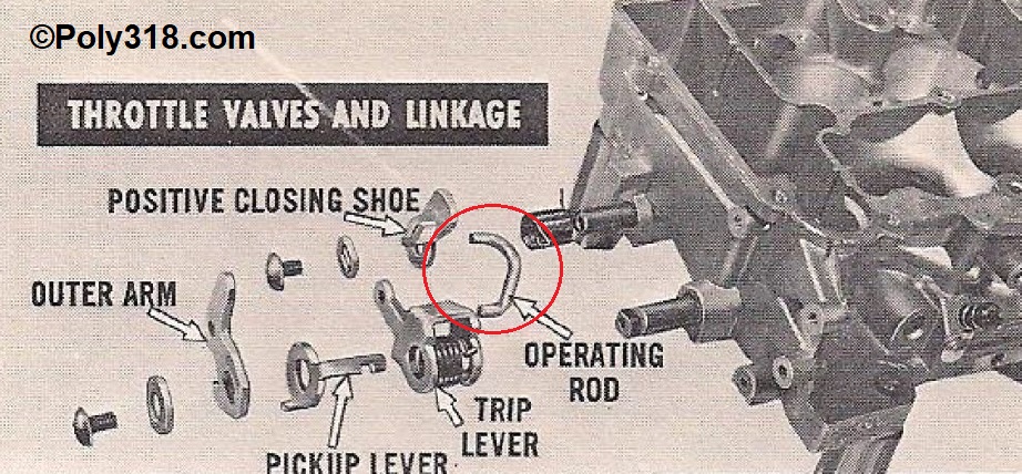
- Confirm that the operating rod (Figure 22) is properly installed with the crown facing up and the open ends facing out. I have come across multiple AFBs with this operating rod installed from the outside, which stops the secondaries from opening more than about 1/4.
- Secondary Lockout Adjustment (Figure 2): Watching the secondary lockout dog, hold the primary throttle open approx. 1/4 and open and close the choke valve. The secondary shaft tang should disengage the lockout dog smoothly and quickly, and the secondary valves should open smoothly. If the tang catches up and stops the secondaries from opening, the secondary shaft tang may need bending or the lockout dog pivot point may be sticking from corrosion or paint. Adjust until the lockout dog drops quickly and the tang does not catch.
- Curb Idle Speed Adjustment (Figure 16), not to be confused with the fast-idle adjustment): Open the primary throttle slightly and move the fast-idle cam to the lowest step. With the carburetor upside down and watching the primary throttle valves, turn the curb idle speed adjuster screw in until the primary valves just start opening. Opening the throttle slightly, move the cam so the screw rests on the second lowest level. Turn the screw in 1 full turn. This setting will ensure that the engine will idle high enough at first startup without the choke actuated so you may adjust idle properly during with the engine hot and running.
Addressing Seized Throttle Shafts
As frustrating as it is, AFB and AVS carburetors that we find at salvage yards, swap meets, and online often have seized throttle shafts because of neglect and design. The AFB/AVS body casting has long protruding portions that carry the throttle shafts. Once corrosion builds up inside these areas, it is very difficult for penetrating oil to soak in to loosen the shaft. Unseizing the shaft takes time, technique, and patience. I have come across multiple carburetors where someone literally twisted the end off the shaft forcing it, beat on the valves with a hammer/drift to where the valves and shaft bent, and one case where the body cracked after taking a beating. Don’t be one of these people who destroys carburetors. In these cases, physics and chemistry are our friends rather than brute force.The process in order of what should be attempted:
- Liberally apply penetrating oil to the throttle shafts, particularly around both sides of the shaft bores in the body allowing the carburetor to rest on its side where the oil soaks down via gravity. Let the oil soak in for a day.
- Alternatively, if you have an ultrasonic bath large enough for the carburetor to sit flat, fill the bath with automatic transmission fluid, Marvel Mystery Oil, or another detergent-heavy oil and use multiple ultrasonic cycles with periods of soaking.
- After soaking the bores/valves, using a brass hammer or brass drift, gently wrap on the stud/screw at the end of the shaft to push the shaft sideways. Wrap on the opposite side of the shaft to move it back, even if you don’t notice movement. Continue this process for a few rounds to see if you can get side-play movement. A completely free shaft has about 1/8” of side-play, so there is room here without damaging the valves/bores. If the shaft begins to move sideways, apply more penetrating oil and continue the process while trying to gently open and close the shaft until the shaft is free. Be careful not to force the shaft open/closed since it can twist.
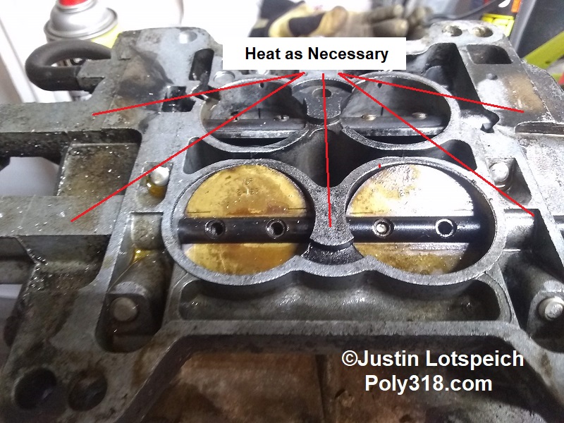
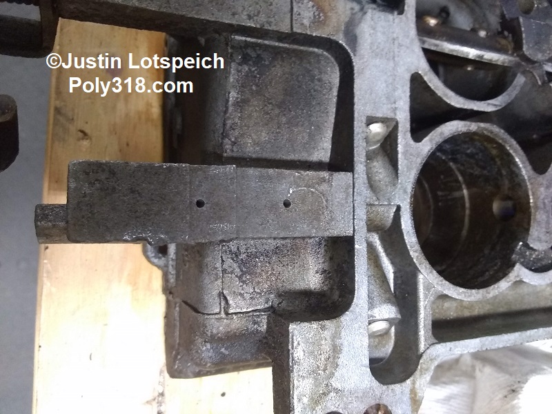
- Using a handheld propane torch or an oxy-acetylene torch turned very low, evenly heat the aluminum body at all three bores trying not to heat the shaft/valves directly (Figure 23). The idea is that metal expands when hot and contracts when cold, so the aluminum body will expand quicker than the steel shaft allowing for a gap to form that can break the corrosion and allow penetrating oil to soak in. Warning: Do not overheat any parts to where they discolor, especially if using an oxy-acetylene torch. After the aluminum is hot, remove the heat and apply penetrating oil to the bores. While the aluminum and oil are hot, wrap the shaft back and forth as described above and try to rotate the shaft by hand being careful not to force it to the point of twisting since it will be warm and more mailable. Warning: The oil will smoke badly and might flame up, so be prepared in a well-ventilated area away from flammables.
- If the shaft remains seized, take two pairs of adjustable pliers or vice-grips and place one on each end of the shaft around the levers. Never place the pliers directly on the throttle shaft. Holding the pliers tight so they don’t slip, very gently apply a small amount of pressure in the open and then closed directions being careful to apply even pressure on both pliers. Watch the throttle shaft and valves closely to see if they try to flex/twist. If you notice the shaft or valve on one side trying to twist but the other side not, you know the one side is free and the seize is in the center and/or opposite side. Warning: Do not apply too much pressure or you can twist the shaft, misaligning the valves and levers.
- At this point, it is time for the surgery. Assuming the seize is in the longer bores, which is most common, center punch two or three approx. equidistance spots in the center of the aluminum bore on the bottom side (Figure 24). Using a quality 1/16” drill bit in a drill press or handheld drill, drill straight down gently and slowly since the bit is small and can easily break off. Keep a magnet nearby, and stop drilling when the magnet begins picking up multiple steel shavings. The drill bit boring into the shaft in these locations will have no adverse effect on the shaft or carburetor vacuum. Clear away the shavings and heat the bore again with the torch. Reapply penetrating oil to the bore ends and at the new holes. Wrap the shaft back and forth. Apply light torque to the shaft end levers open and closed with the pliers. The heat usually sucks the penetrating oil into the new holes, so keep reapplying oil and heat and working through these steps. I have never met an AFB/AVS throttle shaft that didn’t come loose after doing all these steps, but I’m sure my match is out there.
- After the shaft starts to rotate, gently twist it open and closed with the pliers and using penetrating oil and heat until it freely rotates completely open. Do not force the shaft even when it starts moving more.
- All seized shafts need to be removed so you can clean the bores and shafts of corrosion. Open the shaft completely and file off the peened ends of the valve screws all the way to the shaft. A Dremel makes quicker work of the task if you are good enough to not mar the body, valves, or shaft.
- After the peened ends of the screws are filed off, apply penetrating oil to that side of each screw and begin extracting the screws counterclockwise. If they are the factory brass screws, they are very easy to break. Go gently and slowly turning out until finding resistance, then turn in a little, then turn out again. If a screw head breaks off (Figure 23), use a 1/16” drill bit spinning clockwise from the head side of the screw to drill out the screw. The bit will usually dig into the brass and rotate the screw out the other side of the shaft. If not, use an extractor after drilling a hole into/through the screw and chase the threads with a tap/chaser. Warning: Be careful not to mar/strip the shaft threads during drilling.
- After the screws are removed, take a small single-cut file and smooth over both the backside and frontside of the shaft around the screw holes since they will have raised edges from the original machining and peening and can damage the aluminum bore.
- One by one, remove the throttle valves paying attention to their markings and location. Taking photos helps here. Using a sharp object such as an awl, mark each valve with an “L” or “R” based off engine side. Place this letter where the throttle shaft rests on the valve so it can’t be seen after installation and deep enough where cleaning won’t remove it. It is important to match the valve with the bore since they have worn into each other.
- After photographing the shaft-end linkage including the spring tang locations, remove the linkage. Warning: Both the primary and secondary shafts are spring-loaded, so use caution when removing the springs by holding them with needle-nose pliers to release the tension.
- File any raised edges on the shaft end.
- Gently pull and rotate the shaft out of the body. Stop if you feel resistance and inspect the shaft to see if you need to file any obstruction or if the drag is from the internal corrosion. Use heat on the bores as necessary. Warning: Forcing the shaft through the bore can mar the bore, seize the shaft, and/or twist the shaft.
- During the parts cleaning process, use an abrasive hand pad to polish the throttle shaft, removing all corrosion. Use a long steel or brass rifle brush to clean out the body bores of corrosion.
- After the carburetor parts are cleaned and before beginning assembly as detailed above, reinstall the shaft assembly.
- Slide the shaft into the body and rotate it to ensure it moves freely. If not, address the issue.
- With the shaft in the proper rotation from your photographs, slide in both valves in the correct direction and in the correct bore.
- Rotate the shaft to close the valves and keep them in place. Place a small dab of red Loctite onto the steel 6-32 x 1/4” screws and install all screws without tightening them. Note: I purchased a box of 6-32 x 1/4″ steel flathead screws from the hardware store and grind the head diameter down to where they register in the shaft countersinks. You can also purchase replacement screws from carburetor suppliers or rifle screws that have small heads.
- Using a pocket screwdriver catching on the valve markings, rotate the valves to where the alignment markings are evenly parallel with the shaft and the holes are centered with the valves fully closed all around. Snug down the screws tightly.
- While the red Loctite is likely enough, I’m always paranoid about having these little screws eventually vibrate out into the intake where they destroy a valve/piston/engine. I take a pair of needle-nose pliers, position one jaw on the screw-head side of the shaft and the other jaw on the very edge of the protruding screw threads. Clamp down, mashing the threads flat down the side and mushrooming the tip of the screw. I do this on both sides of the screws to essentially peen them over. Be careful not to damage the valves during this process. Blow off the body/valves/shafts of any shavings. Warning: Never beat on the screw ends to peen them since the throttle shaft/valves will bend.
- Reinstall the spring and linkage to the end of the shaft, and proceed with the assembly instructions above.
Figures