Poly 318 Marine and Industrial Engines
Introduction
I had no idea that what started as a Peruvian poly A-block 318 marine enthusiast emailing me a single photo would turn into a rabbit hole that consumed months of evenings researching and writing with my share of frustrating dead ends but exciting moments of discovery. Poly A318 marine and industrial engines are about as unique a factory niche in the A-block world as you can get, save for the very few factory performance 1956 277s Plymouth experimented with that I’ve yet to find enough evidence to write about. As I delved into the marine world, I kept running across more information about industrial poly A318 engines as well since both the marine and industrial engines were for a number of years managed by Chrysler Corporation’s “Special Products Group.” There I was two-hundred feet into this rabbit hole and after purchasing a marine factory service manual and an industrial factory operating manual when I was comfortable enough with the evidence I had to create this page. The irony is that I am not a boating enthusiast and have no need for an industrial engine, although after this experience I don’t know that I would turn down the chance to own a wooden boat with an inboard A318. I still have gaps to fill in this page and welcome readers to email me if they have information. I present you with the marine M-Series poly 318 and the industrial H-Series poly 318.
Poly 318 Marine and Industrial Engine History
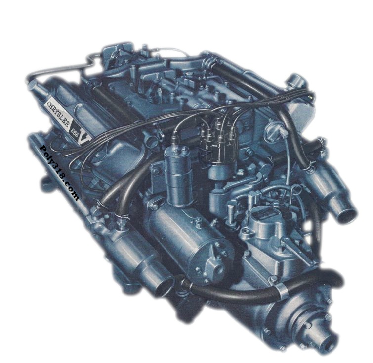
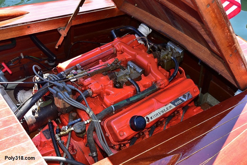
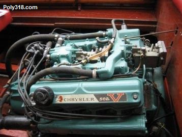
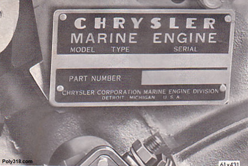
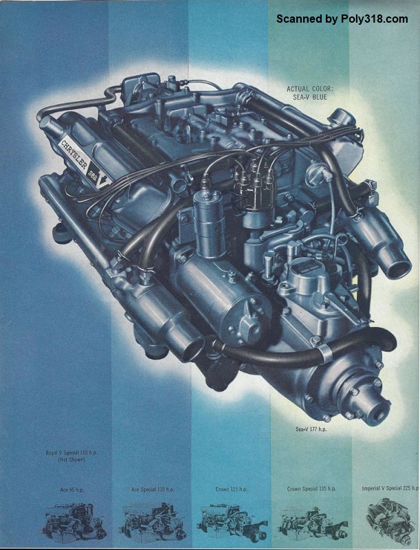
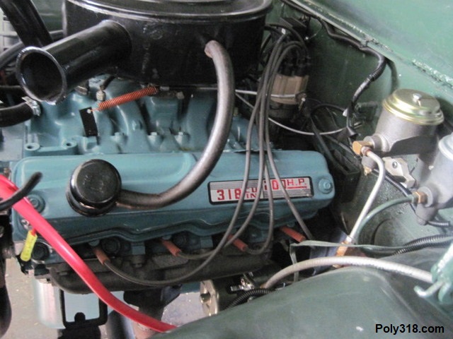
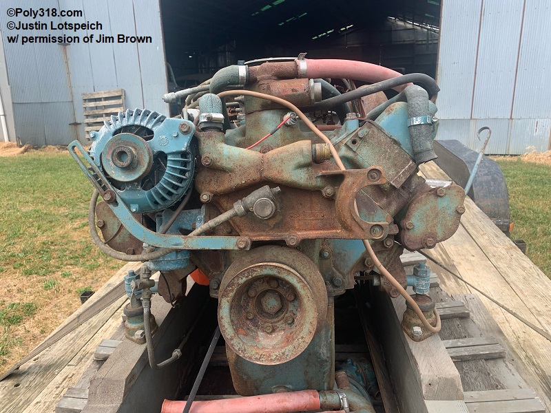
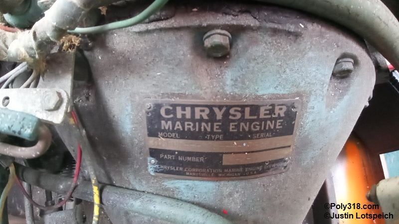
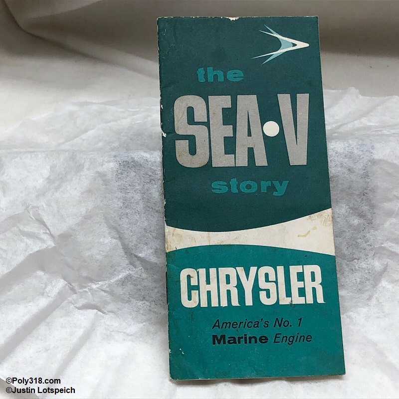
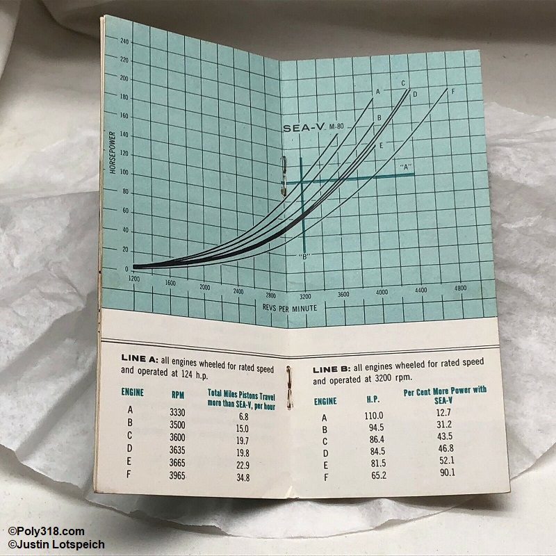
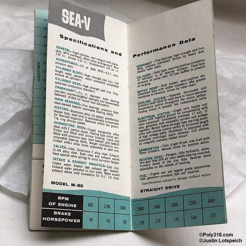
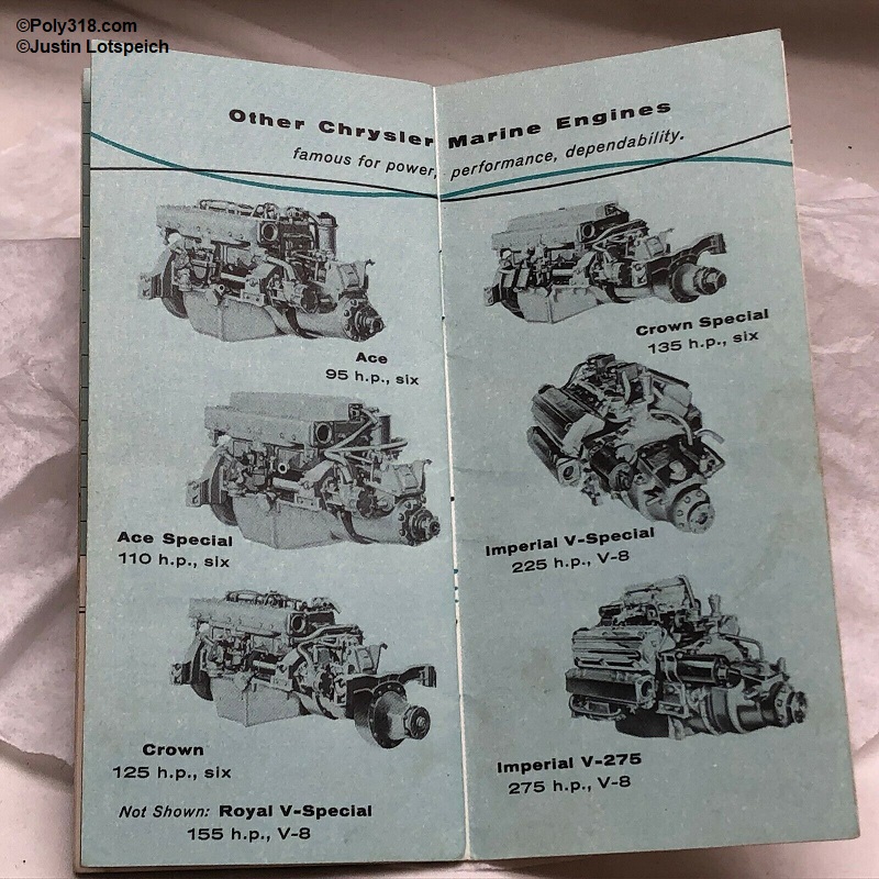
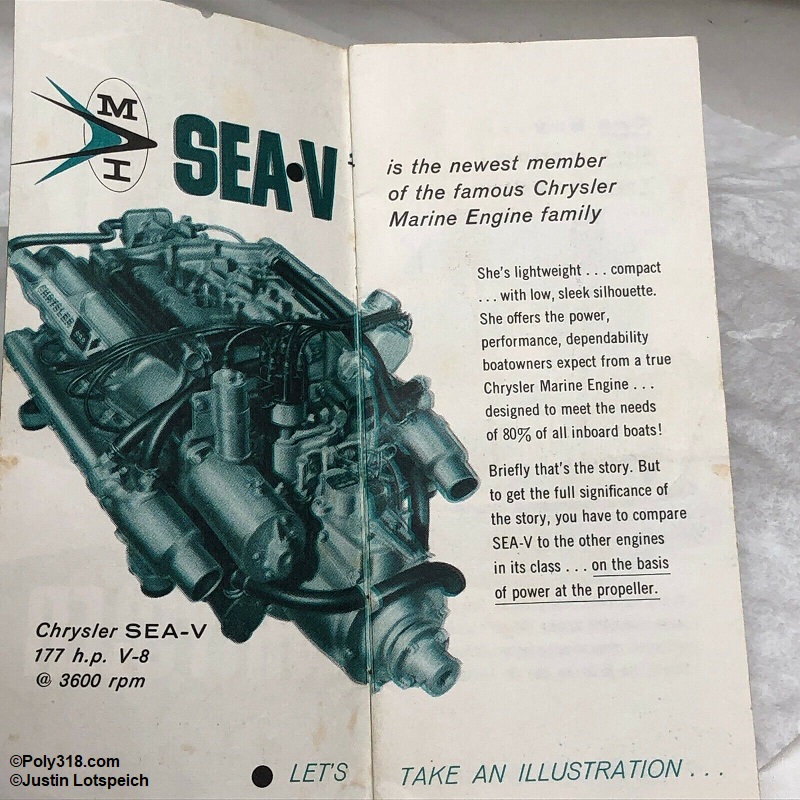
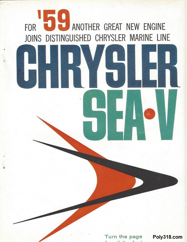
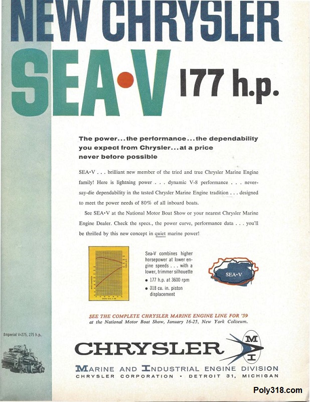
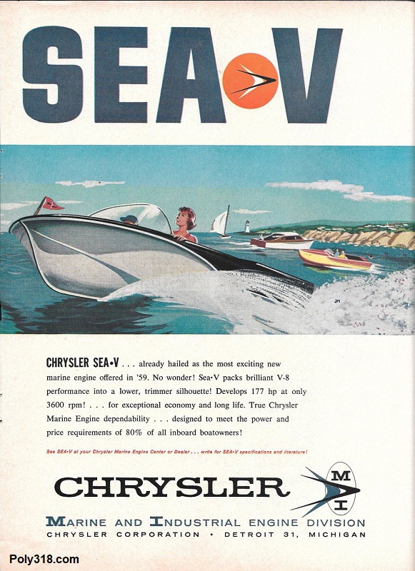
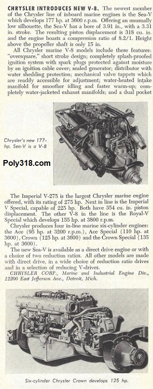
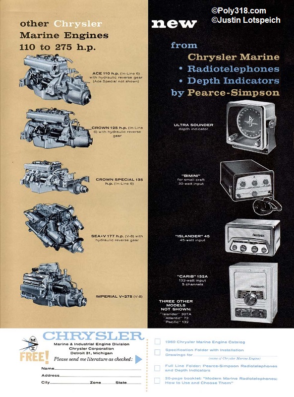
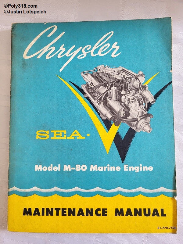
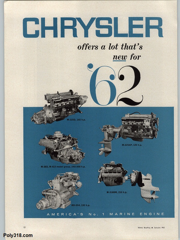
Before 1959, Mopar’s V8 boat engine options were restricted to Gen I 354 Hemi in the “Imperial V-275,” “Imperial Special,” and the “Royal V Special.” With the success of Plymouth’s A-block engine first debuted in Plymouth cars in 1956 and Chrysler cars in 1958, Chrysler’s Industrial and Marine Engine Division introduced the first marine “M-Series” A-block 318 in 1959 with the “Chrysler Sea V” advertised at 177 HP with its unique valve-cover decal (Figures 1a – 1c). It took me a lot of research and examining different factory service manuals and advertisements to figure out that while the overall division was called the “Industrial and Marine Engine Division,” Chrysler built and sold the marine engines under the “Chrysler Corporation Marine Engine Division” that was used in both printed material and on engine plates from 1959 – 1967. The A318 marine engines from 1959 – 1967 fall under the “M-Series” engine class along with B-block 383 and RB-block 413 options.
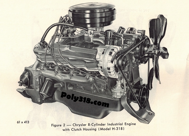
In 1959, the Industrial and Marine Engine Division under the name Chrysler Corporation Industrial Engine Division also released the first industrial A-block 318 known as the “H-Series” (Figure 1d). This series would run from 1959 through 1967 and helped solidify Chrysler Corporation as a major competitor in industrial equipment. The H Series A-block 318 engines include the H318, HB318, HC318, and HT318 depending on the application, which was originally stamped into an identification plate riveted to the engine. The “H” indicates a light-duty engine, HB medium-duty, HC high-compression, and HT heavy duty. According to the operating manual, engines were used in “delivery trucks, street sweepers, lift trucks, navigation and stand-by pumps, wind machines, mobile air conditioners, crane carriers, hoisting equipment, welding generators, tow tractors, concrete mixers, orchard sprayers, and many other industrial applications.”
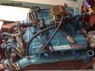
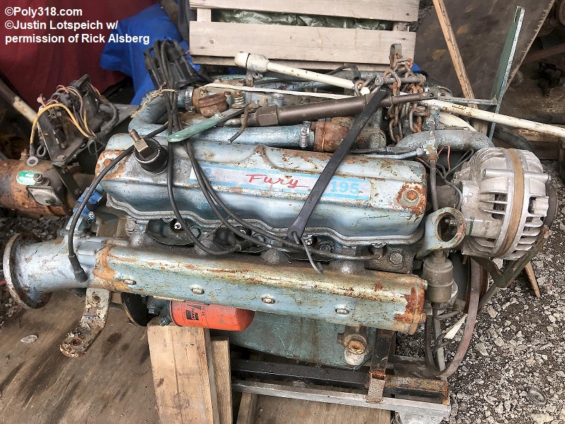
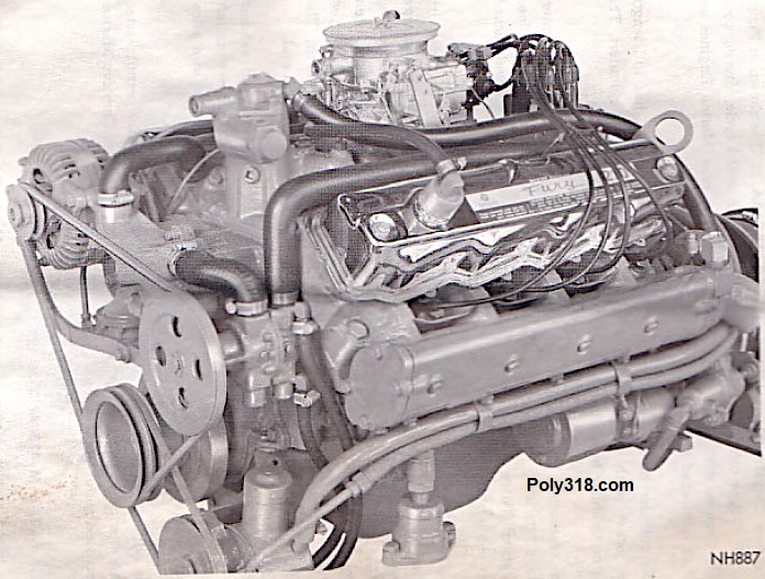
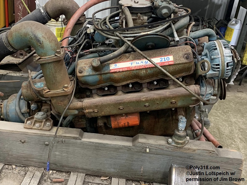
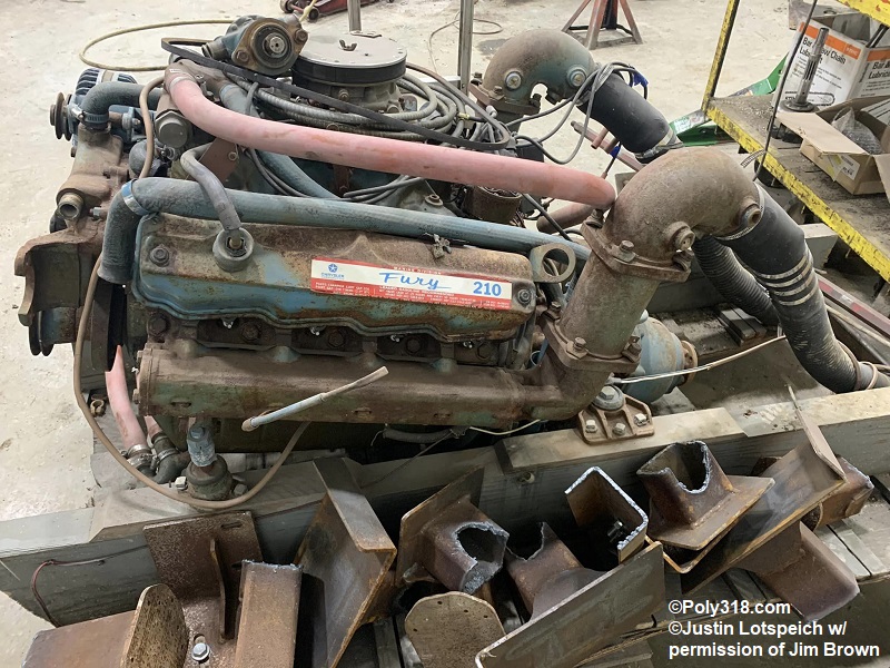
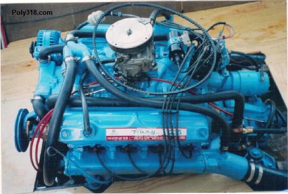
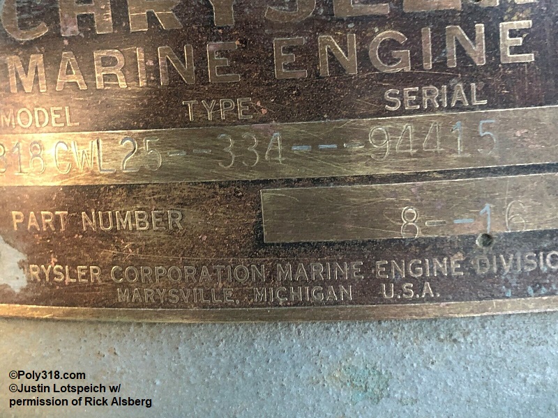
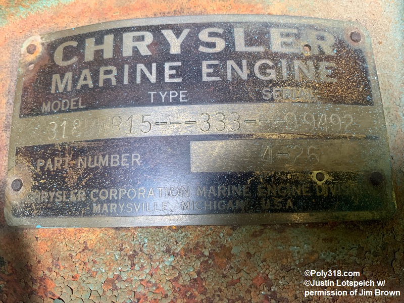
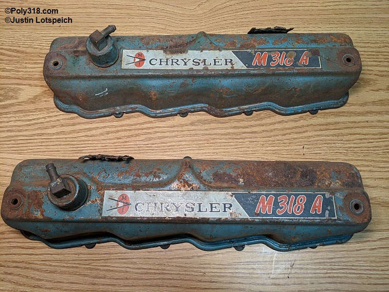
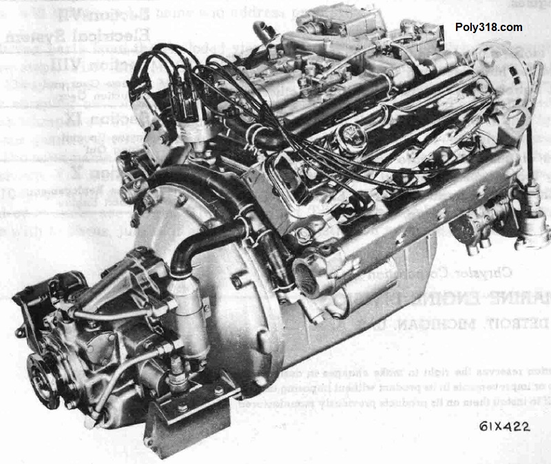
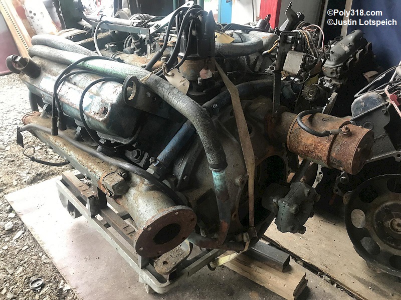
While the industrial H-Series maintained its naming system consistently, the marine M-Series went through some names early on before standardizing the series. I haven’t found historical information to pinpoint when the the Marine Engine Division released the “Chrysler M318A,” a factory service manual and unrestored boats I found with the “M318A” name and unique valve cover decal suggest the change was somewhere around 1960 (Figure 2a – 2b). In 1963, the Marine Engine Division sought to standardize their marine engines and introduced the “Fury” line including the “Fury 190” model M318A (no photo), “Fury 195” model M318B (Figure 3), “Fury 210” model M318C (Figure 4a – 4c), and “Fury 235” (Figure 5) named after their advertised BHP. Of note, the Fury 190 took on the model name of its predecessor the “M318A,” which confused me for a long time until I realized Chrysler had rebranded the engine. With the introduction of the Fury line in 1963, the Marine Division began using a different engine tag that would last through 1967 (Figure 6a – 6d). The “Chrysler M318A” and “Chrysler Sea V” with their unique valve cover decals were retired in 1962 and replaced in 1963 by the Fury line. Information about the Fury 190 alludes me, but it appears the engine model was likely only used for one year in 1963 since by 1964 advertisements only list the Fury 195, 210, and 235 that would be the only available A-blocks through 1967. The “Fury 235” requires more research since I cannot find a model for it even though the logical assumption would be “M318D” since the “Fury 210” is M318C.


Marine Engine Identification Codes and Specifications
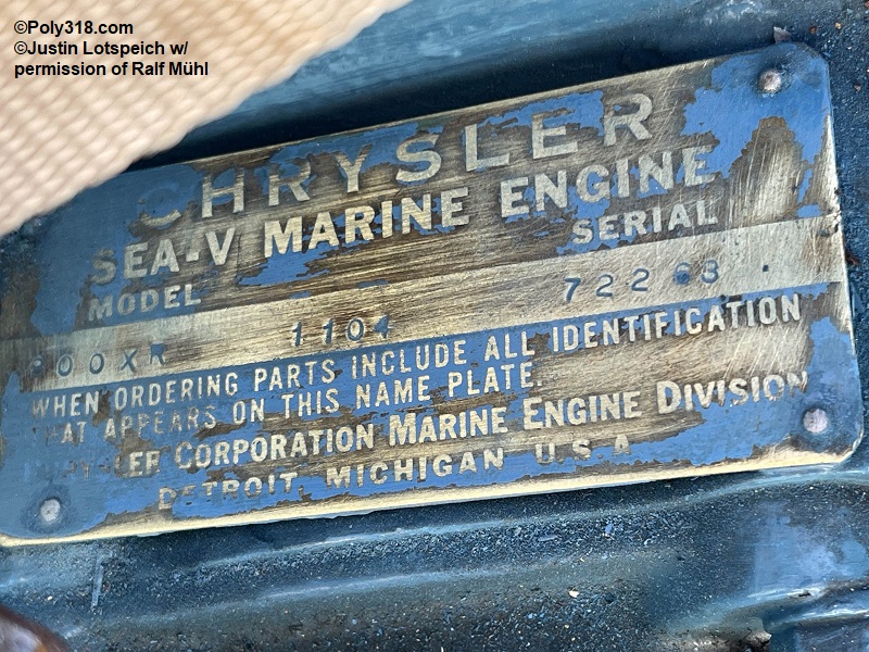
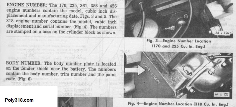
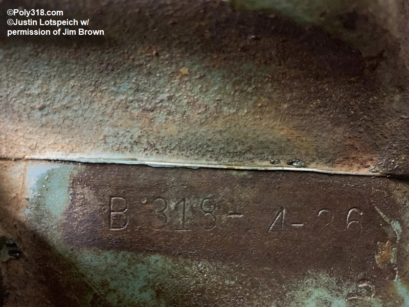
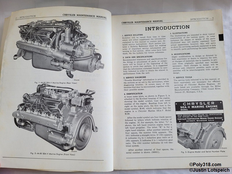
1959 – 1967 A318 blocks use the same date prefix letter stamped into the block on the upper left of the block just below the cylinder head seen in Figures 6a and 6b. For these date codes, see the engine numbers page. However, they originally had a unique tag. Looking at the Marine Engine tag under “Model,”
- “800X” was used for the first marine A-block, the Chrysler Sea V. “318A” denotes a Fury 190. “318B” denotes a Fury 195. “318C” denotes a Fury 210, and “318D” and “318XY” denote a Fury 235.
- The “L” or “R” denotes the engine rotation when viewing the engine from the stern forward, as in when standing in front of the flywheel. R = right-hand (aka reverse) rotation. L = left-hand rotation. A left-hand rotation is the standard for cars/trucks for comparison.
- The next number indicates the reduction ratio of the reverse gear: “10” = 1:1, “15” = 1.5:1, “25” = 2.5:1. Some tags used letters to code the gear ratio, although I have not been able to confirm which letters mean which ratio.
The numbers under “Type” refer to the optional equipment originally fitted to the engine, such as straight drive reduction gear, etc. Unfortunately, I have not been able to locate a factory index identifying what each equipment was numbered. The last group of numbers is the serial number that at one time could be used by a dealership to obtain the build sheet, but that information has been lost to history.
1959 – 1962 A318 marine engines don’t appear to use any uniform suffix in stamped identification number. I have found multiple suffixes used on A318 marine engines from 1959 -1967 with most using the “Standard” engine package denoted by a “-1” (as in X318-1) but some with a unique “-4” (as in X318-4). The “Standard” engine package was used in almost all consumer cars and light trucks and has the specifications below, and the factory Marine Division advertisements I’ve found confirm that the “Standard” package was likely the one used in marine engines with the mechanical camshaft and lifters and no exhaust valve rotators being the giveaway. I was fortunate to communicate with the owner of an original 1964 “Fury 210” that still had the factory head gaskets and bearings who sent me photos confirming the engine had the -1 “Standard” components that include
- Standard non-roller timing chain
- Standard steel-backed babbitt bearings
- Standard pressure/volume oil pump
- Mechanical camshaft and lifters
- Adjustable rocker arms
- Standard valves and retainers
I gathered the following marine engine details from period advertisements and factory service manuals:
Hard Parts
- Splash-proof ignition system
- Moisture-proof spark plug ignition cable cover
- Sealed generator
- Water-shedding distributor
- Mechanical camshaft and lifters with adjustable rocker arms
- Water-heated intake manifold
- Completely water-jacketed exhaust manifolds
- A choice of direct drive or reduction ratios
Bore: 3.91”
Stroke: 3.31”
Compression Ratio
- Chrysler Sea V: 8.2:1
- Early Chrysler M318A: 8.2:1
- Fury 190 M318A: 8.2:1
- Fury 195 M318B: 8.2:1
- Fury 210 M318C: 8.2:1
- Fury 235: likely 9:1
Cylinder Pressure (All Models): 120 – 150 PSI at 150 – 200 RPM with 20 PSI maximum variation between cylinders
Oil Pressure at 2,000 RPM (All Models): 45 – 65 PSI
BHP:
- Chrysler Sea V: 177 @ 3,600 RPM
- Early Chrysler M318A: 190 @ 4,000 RPM
- Fury 190 M318A: 190 @ 4,000 RPM
- Fury 195 M318C: 195 @ 4,000 RPM
- Fury 210 M318B: 210 @ 4,000 RPM
- Fury 235: 235 @ 4,000 RPM
Torque (approximated from a factory service manual power curve chart)
- Chrysler Sea V: Unknown
- Early Chrysler M318A: Likely 270 @ 4,000 RPM
- Fury 190 M318A: 270 @ 4,000 RPM
- Fury 195 M318C: 275 @ 4,000 RPM
- Fury 210 M318B: 290 @ 4,000 RPM
- Fury 235: Likely around 340 @ 4,000 RPM comparing the 235 HP to the 230 HP car engine.
Factory Poly 318 Marine Engine Colors
Factory marine engines from 1959 – 1961 and some 1962 were painted a unique medium metallic blue called “Sea-V Blue” (Figures 7a – 7b). While no commercial match exists, Bill Hirsch “Oldsmobile 455 Metallic Blue” is too blue and too dark (Figure 7c). “Pontiac Metallic Blue” is too light but looks closer to the correct hue. I think ordering a pint of the “Oldsmobile 455 Metallic Blue” and a quart of the “Pontiac Metallic Blue” and mixing the Oldsmobile into the Pontiac to darken it to the desired value will work. One other option that might work is to use a method we used in the body shop with candy paint jobs where the clear coat is tinted with color. In this case, paint the engine with a couple coats of Pontiac Metallic Blue until achieving full coverage. After the final coat tacks off, fog on a thin coat of the Oldsmobile 455 Metallic Blue to darken the value. If more darkening is desired, fog on another coat after the first one tacks off. A final option is to somehow locate a paint chip for the “Sea-V Blue,” which I imagine will be extremely difficult, and have a paint supplier or autobody shop mix the color.
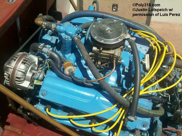
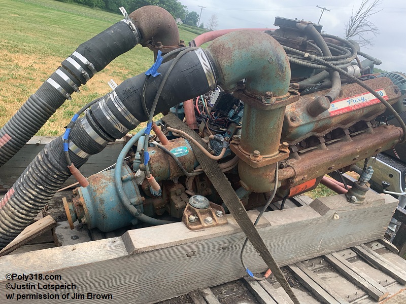
1963 – 1967 marine engines were painted Chrysler Turquoise, the same color used on 1962 – 1964 Dodge trucks equipped with the 200 HP and 202 HP A318 packages (Figure 7d). Dupli-Color DE1618 and Bill Hirsch “Chrysler Turquoise” are exact. Mopar P4120752 is often too blue. An interesting detail I found after reading a factory service manual and a factory owner’s manual is that 1962 – 1967 marine engines were offered with optional chrome valve covers (Figure 7e – 7f).
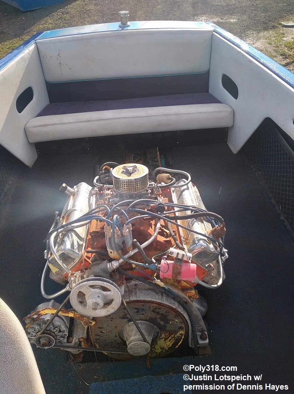
Keep in mind that private boat companies could paint an engine whatever color they or their customer desired and that some of the photos I include on this page show engines that have been repainted a color different than the factory color. There’s no evidence in advertisements and original vintage photos that the A-block marine engines were ever painted Chrysler Red or Chrysler Corporation Blue from the factory.

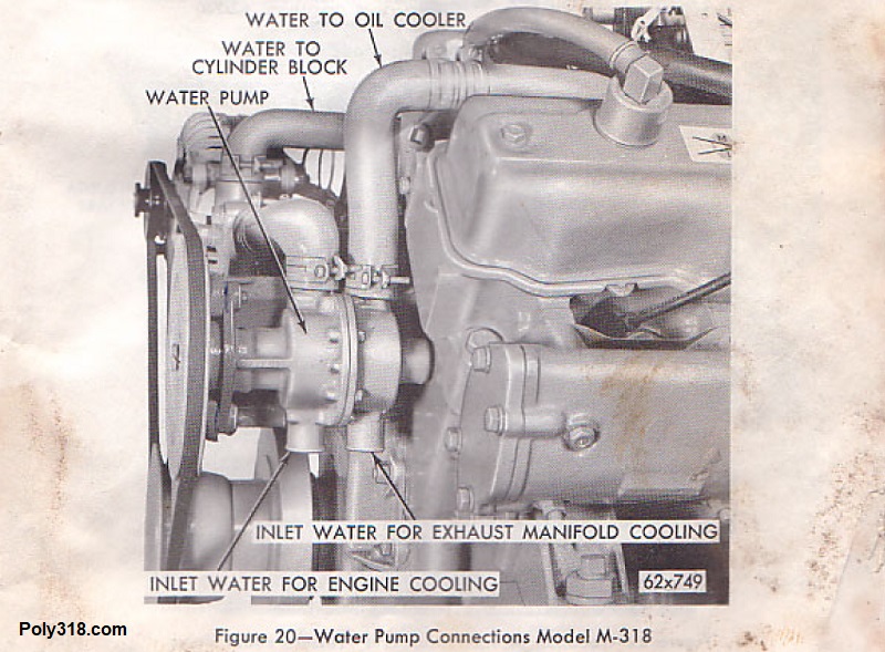
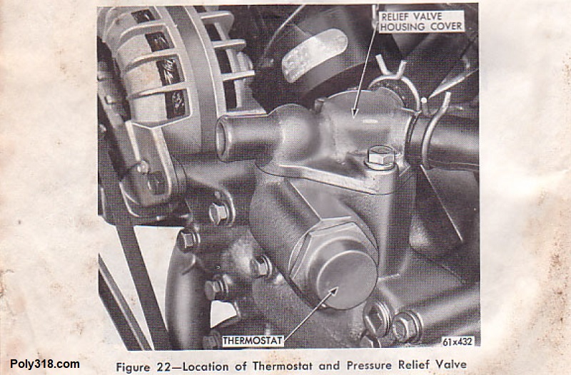
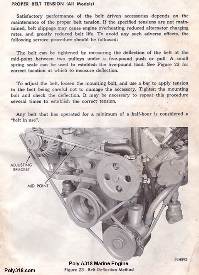
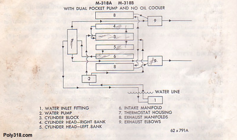
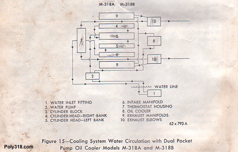
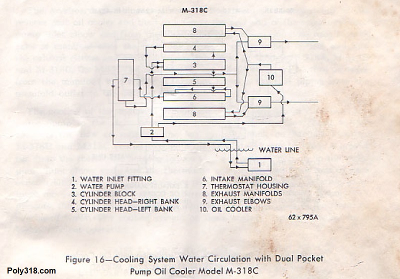
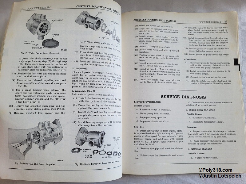
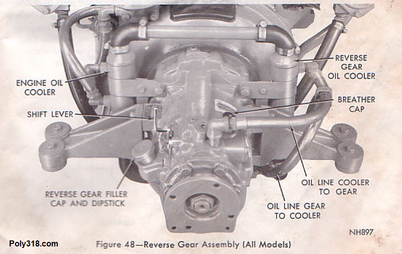
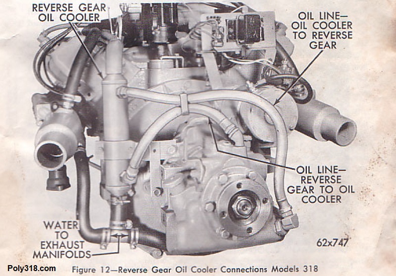
Poly 318 Marine Cooling System
Because the marine engines have a unique cooling system, I wanted to provide details I’ve found in factory owner’s and service manuals.
Poly 318 Marine Rotations, Ignition Timing, and Electrical
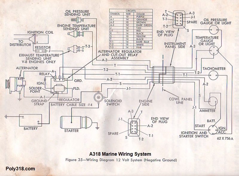
Because the marine engines have a unique electrical system as possibly unique firing order, I wanted to provide details I found in factory owner’s and service manuals.
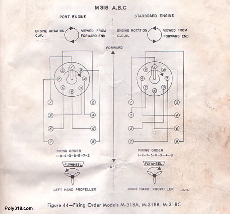
Depending on the vessel’s configuration, the marine A318 crankshaft viewed from the front could have either a clockwise rotation like cars and trucks or a counterclockwise rotation unique to marine engines. Refer to the figures below since the terminology can be confusing because the crankshaft rotation is viewed from the front of the engine while the propeller rotation is viewed from the back of the engine. For clockwise crank rotation with the standard 18436572 firing order, the propeller turns counterclockwise. For counterclockwise crank rotation with the unique 12756348 firing order, the propeller turns clockwise. The camshaft dictates the firing order and rotation. For people who have marine A318 engines that they want to use in cars and trucks, the engine’s rotation should be identified and if needed changed to the standard clockwise rotation.
Poly 318 Marine Parts
The marine engines have unique parts not used on vehicle and industrial applications. Some of these parts may have been produced by the Chrysler Marine Engine Division, but many appear to be supplied by different manufacturers. This collection is limited to what I have been able to find online, at swap meets, and from people emailing me photos of their parts.
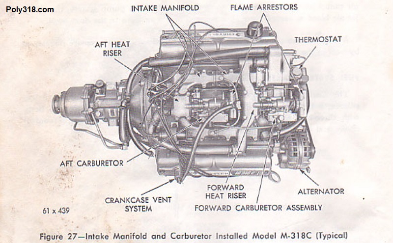
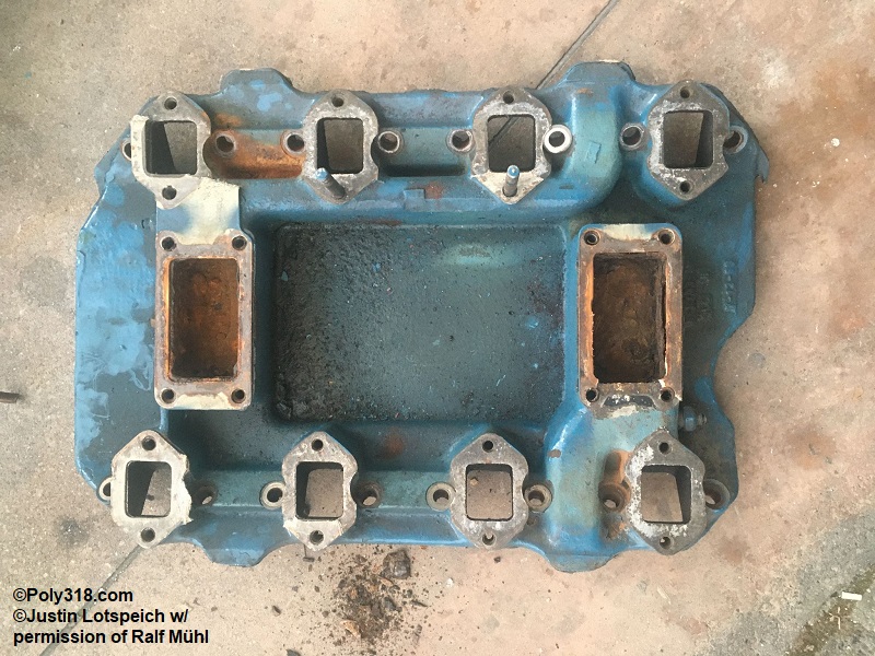
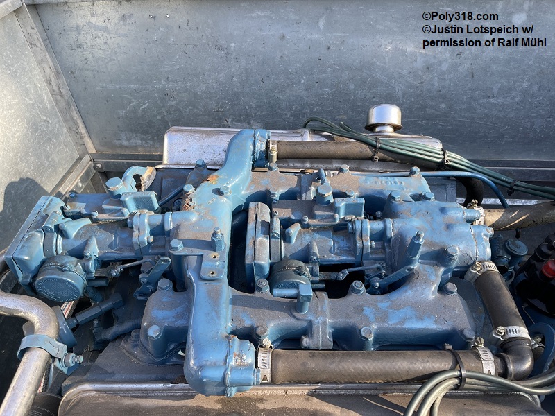
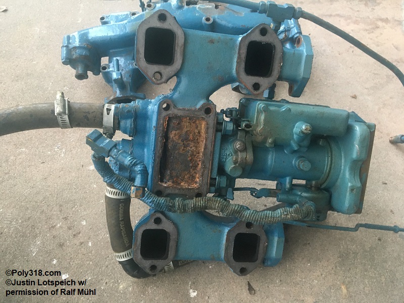
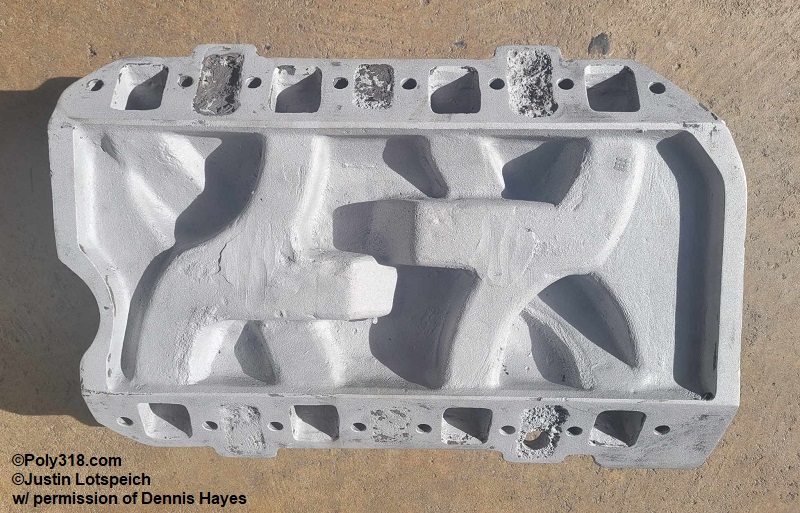
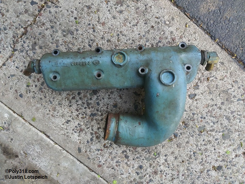
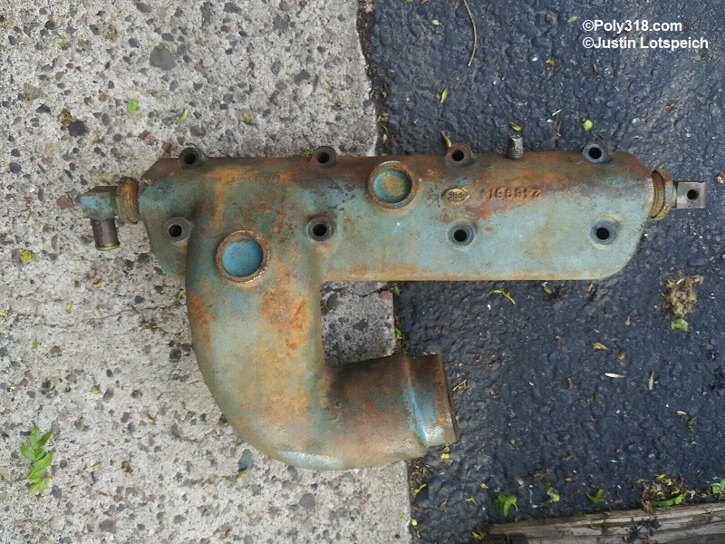
Intake manifold (for dual Carter YH carburetors, Figures 8a – 8c)
- Note: Vintage advertisements, factory manuals, and photos show this unique marine intake manifold on early engines such as the Chrysler Sea V and the M318A, but at some point, likely in 1962, the engines received a single four-barrel intake manifold, Carter marine AFB, and Bendix Zenith marine air cleaner.
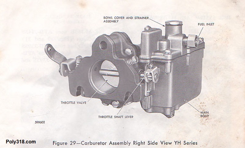
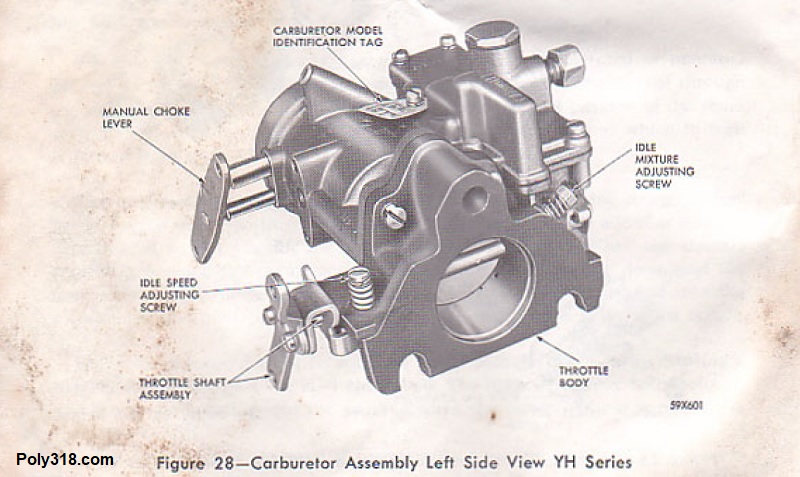
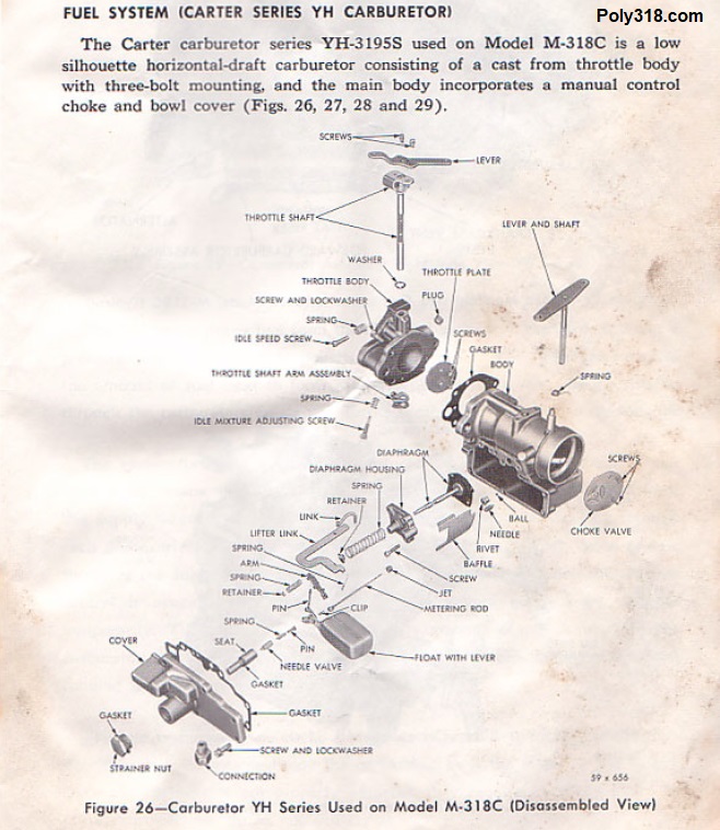
Carter YH-2991S Marine Carburetors (Figures 8d – 8g)
- Note: Rebuild parts are still available through Mike’s Carburetor Parts, who is my go-to supplier for Carter AFB rebuilding and tuning parts.
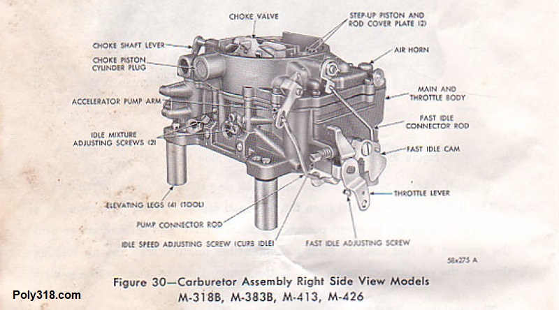
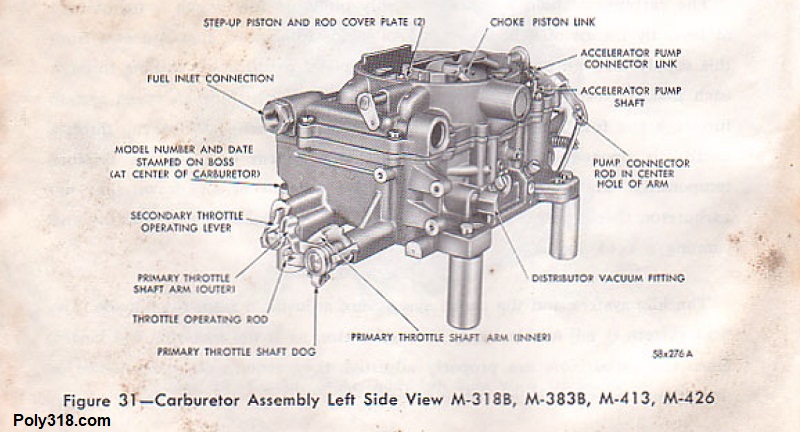
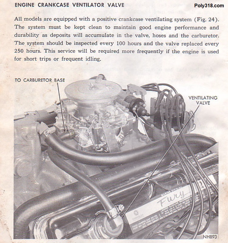
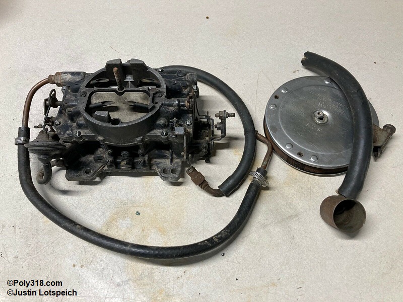
Carter AFB Marine Four Barrel Carburetor (Figure 8h – 8j)
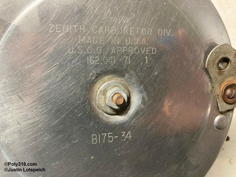
Bendix Zenith Marine Air Cleaner (Figure 8k – 8l)
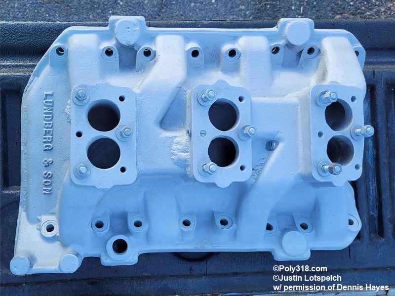
Performance Intake Manifold, Lundberg & Son, Australia, 3 x 2 Rochester or Stromberg carburetors (Figure 8m – 8n)
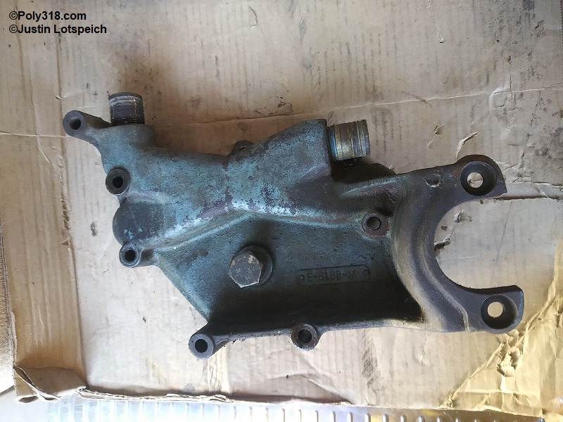
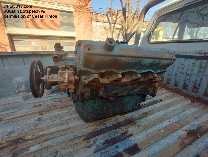
Timing cover water crossover and incorporated alternator and external water pump mounts (Figure 9a – 9b)
Coolant splitter (Figure 9c, attached at the thermostat well)
External water pump (Figures 9d – 9e, some located on the front and some on the rear of the engine)
Deep-sump, 8-quart capacity oil pan and dipstick (Figure 9e)
- Adding 1 quart for the oil filter, the marine A318 held 9 quartz of oil to be measured at 7° engine angle.
Exhaust manifolds (either rear/front dump Figure 10a or side dump Figures 10b – 10c)
- While the photo is too grainy for me to publish here, I found a NOS rear-dump manifold just like Figure 10a that on the bottom has raised letters “Marine Phila V8.”
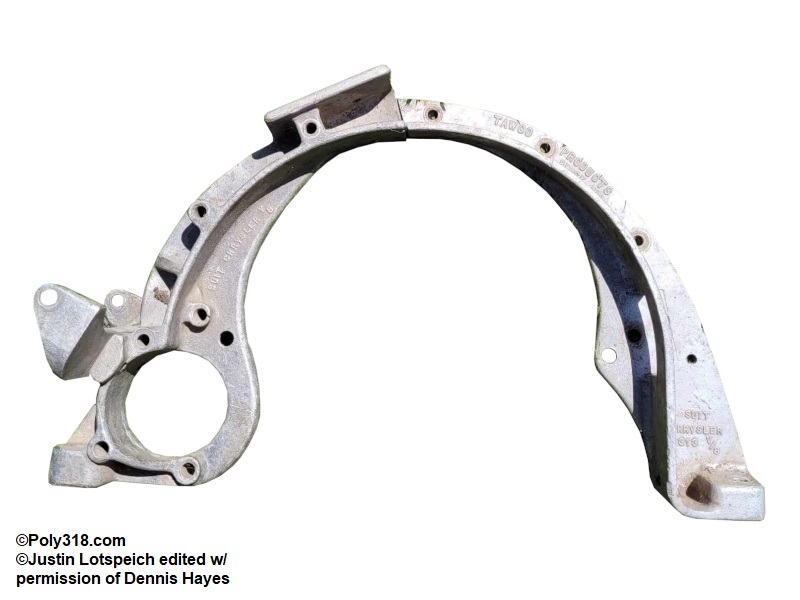
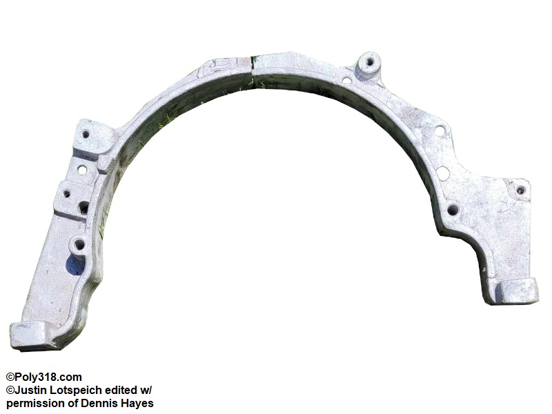
Bellhousing adapter for mounting, starter motor, water pump, and/or alternator (Figures 11a – 11e)
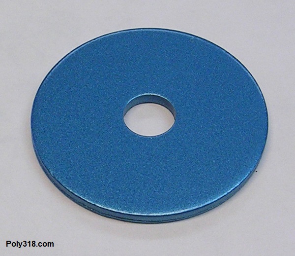
Flywheel pulley (Figure 11f)
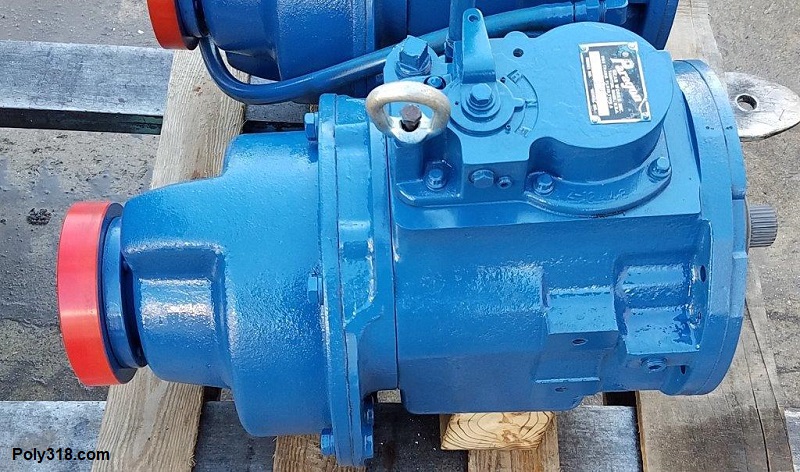
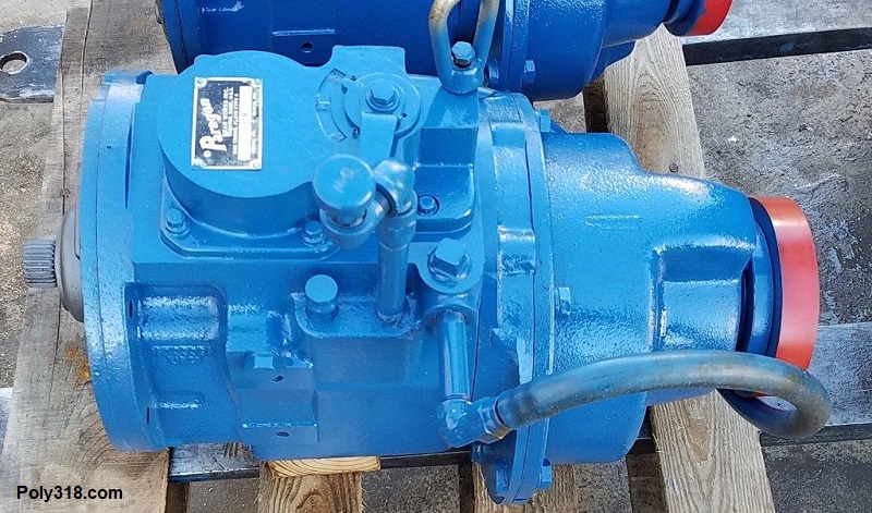
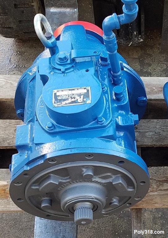
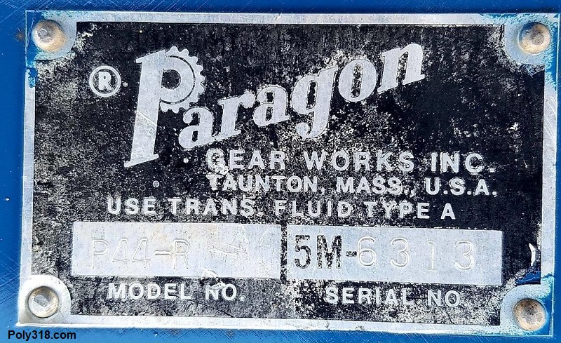
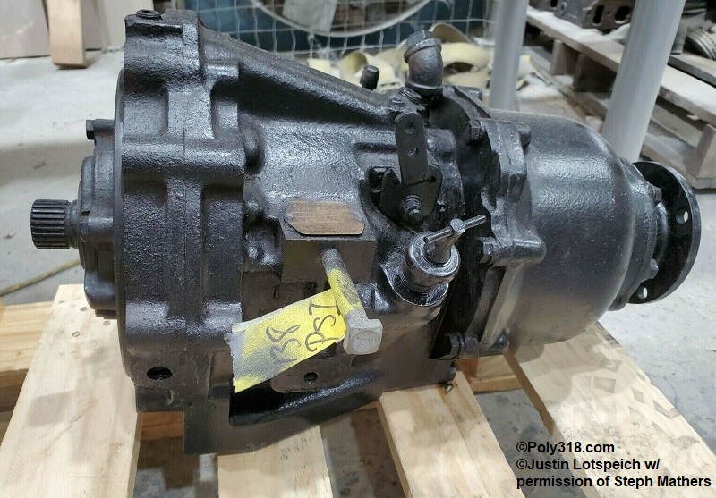
Paragon Gear Works Gear Box (Figures 12a – 12d)
- One of my favorite breakthroughs in the marine research was finally discovering the illusive gear box found on the 1959 Chrysler Sea V” factory advertisements. It took a lot of digging, but I finally found the Paragon gear box. While I am not for certain, I believe the model line used was the PL. The closest gear box I could find is the P44-R, which appears very close to the 1959 advertisements but with a different output housing. Until I find the identical gear box, the images I provide here must suffice. Unfortunately, I do not know when the Marine Engine Division switched from the Paragon box to the Borg Warner below.
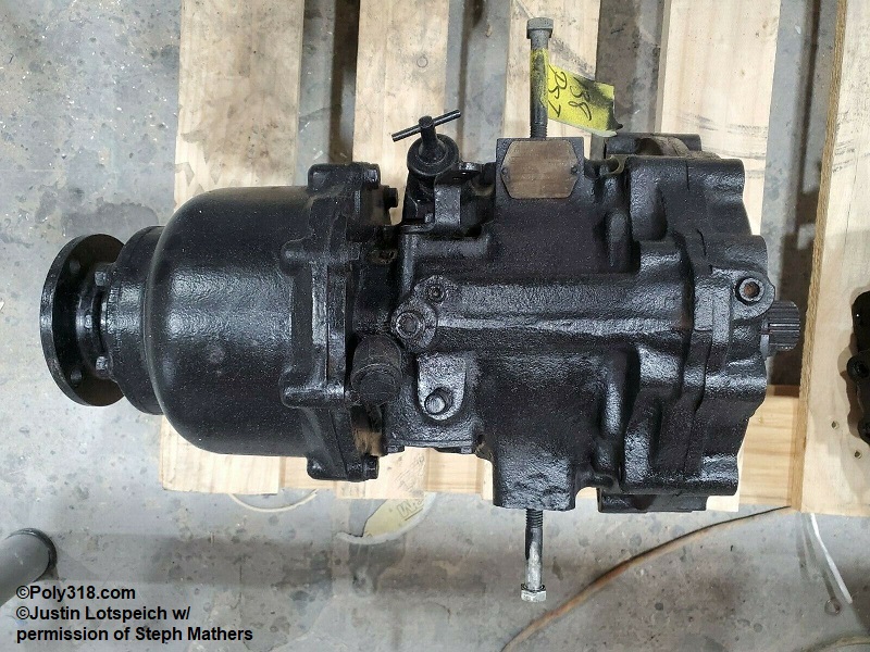
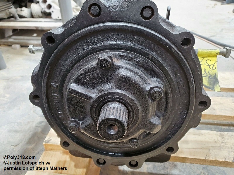
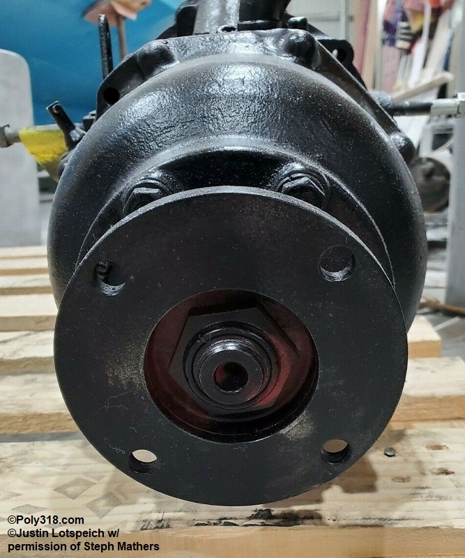
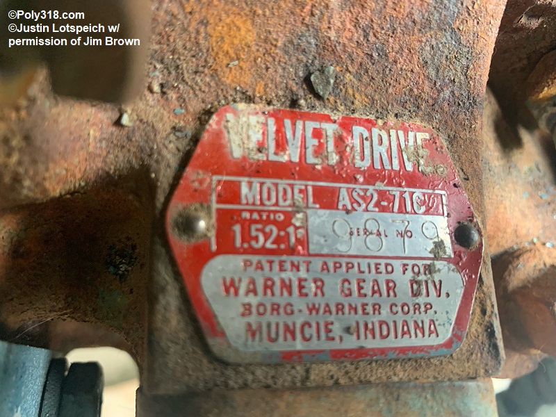
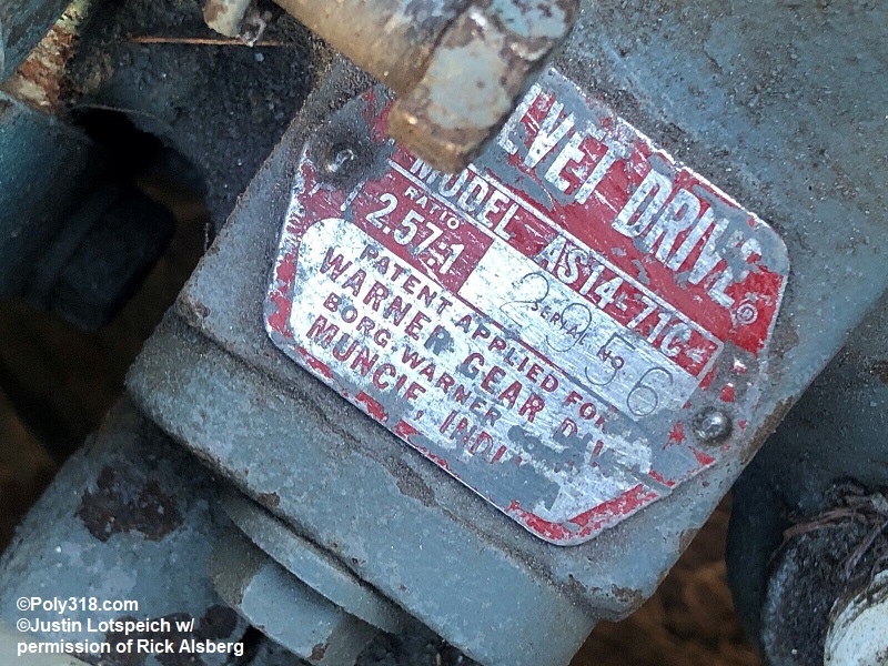
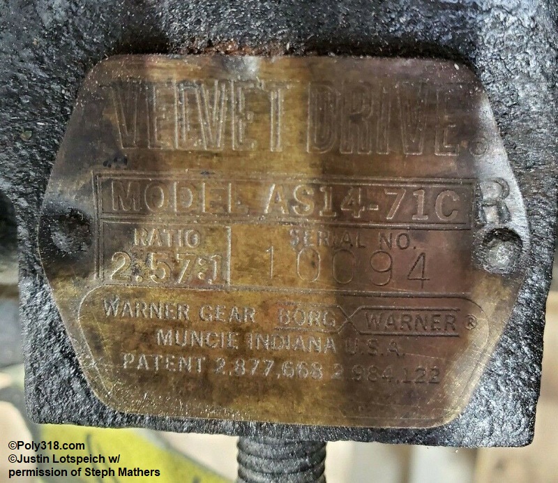
Borg Warner “Velvet Drive” Gear Box (Figures 13a – 13i)
- Note: The A318 marine engines appear to use the Borg Warner “Velvet Drive” gear box from around 1962, when the A318 bellhousing changed, through 1967.
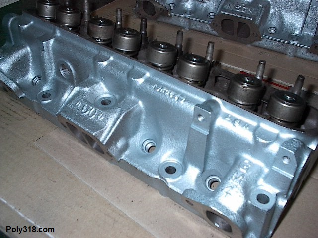
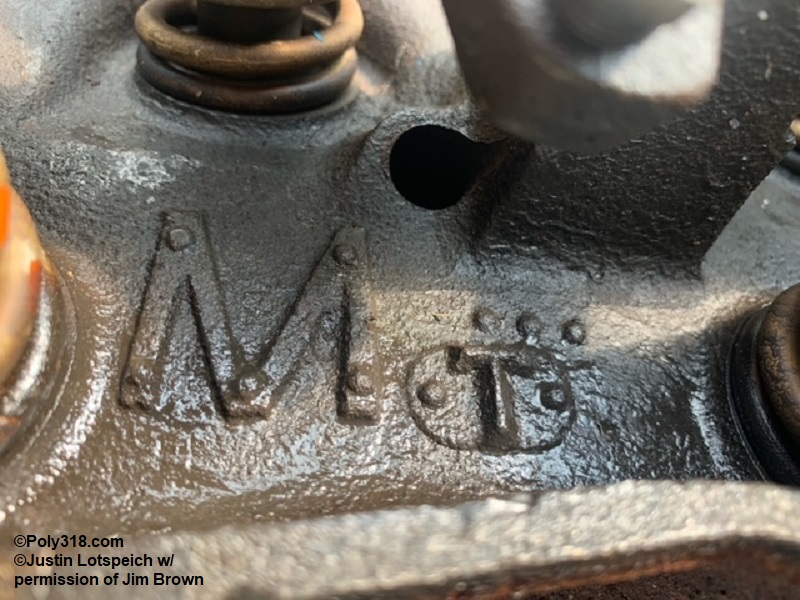
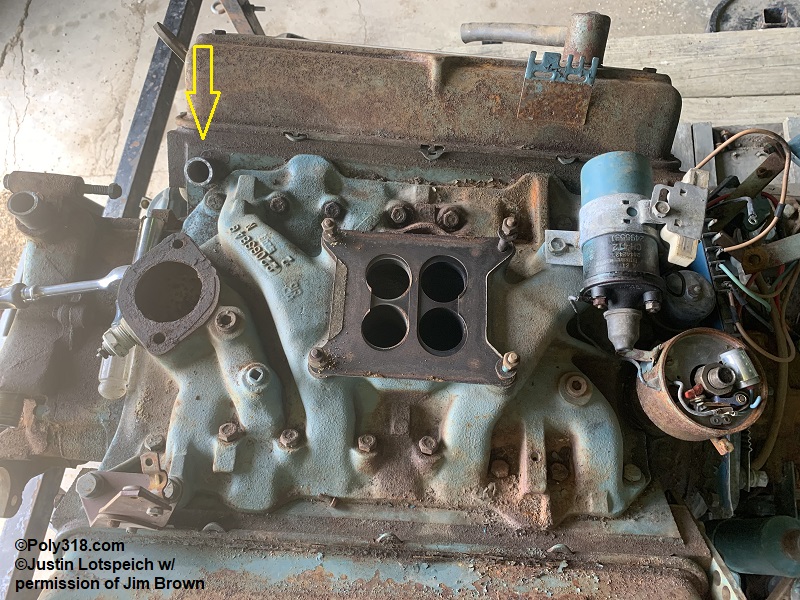
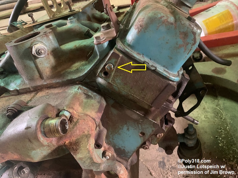
Some marine engines received a unique cylinder head. The head uses the same casting number 2268341 as automotive engines, but is has a very unique “M” cast into the top (Figure 14a). These heads have two distinct additional coolant ports drilled and tapped: one is located at the right (passenger) front of the head on the intake-manifold flange (Figure 14b), and the other is located on the left (driver) side front of the head just above the lower accessories boss (Figure 14c).
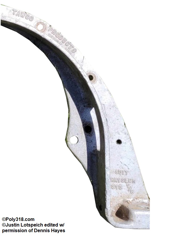
Note the “Chrysler 313” suggests this adapter was expected to be used when people converted the imported A313 (an under-bored A318) to a marine application
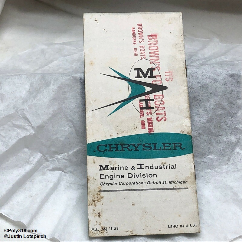
Poly 318 Marine Advertisements and Manuals
Industrial A-block Poly 318 “H-Series” Engines

I have far less information about industrial A318 engines but purchased a 1962 factory operating manual that I scanned in for free download on the manuals page. The manual provides solid evidence regarding the internal and external components used in many industrial engines. Chrysler Corporations Industrial Engine Division under the management of the Special Products Group began offering the A-block poly 318 industrial engine in 1959 and carried the engine through 1967. The H Series A-block 318 engines include the H318, HB318, HC318, and HT318 depending on the application. The “H” indicates a light-duty engine, HB medium-duty, HC high-compression, and HT heavy duty. According to the manual, engines were used in “delivery trucks, street sweepers, lift trucks, navigation and stand-by pumps, wind machines, mobile air conditioners, crane carriers, hoisting equipment, welding generators, tow tractors, concrete mixers, orchard sprayers, and many other industrial applications.” Industrial engines received the following components:
- “Silent” timing chain for the H318 and HC318
- Roller timing chain for the HB318 and HT318
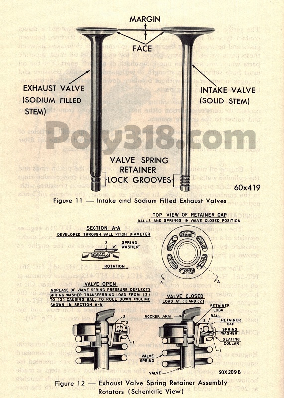
- Silchrome intake valves for all models (Figure 13a)
- Stellite-faced exhaust valves in the HB318 and HT318 (Figure 13a)
- Hydraulic camshaft and lifters for the HB318 and HT318 with non-adjustable rocker arms
- Mechanical camshaft and lifters for the H318 and HC318 with adjustable rocker arms
- Steel-backed babbit main and rod bearings for the H318 and HC318
- Tri-metal main and rod bearing for the HB318 and HT318
- Standard forged crankshaft for the H318 and HC318
- Hardened shot-peened forged crankshaft for the HB318 and HT318
- Standard volume and pressure oil pump for all models
- Some applications were equipped with a dual oil filter
- Exhaust valve rotators and special valve springs for the HT318 (Figure 13a)
- Front and rear saddle engine mounts depending on application
- Unique gearbox setups depending on application. These may include heavy duty clutches and “Industrial Torque Converters” that use specialized bellhousings.
- The HT318 had an option for a “power take-off clutch assembly” with a special mid-shaft that ran from the clutch to the driveshaft with a double-row of ball-bearings at the front and two tapered roller bearings at the rear of the bellhousing.
- Gearbox options included the standard A745 3-speed, standard T87E 3-speed, standard New Process 420 4-speed, standard New Process 433D 4-speed, standard New Process 540 5-speed, and the TorqueFlite A727 that Dodge trucks and the Industrial Engine Division called the LoadFlite from 1962 – 1965.
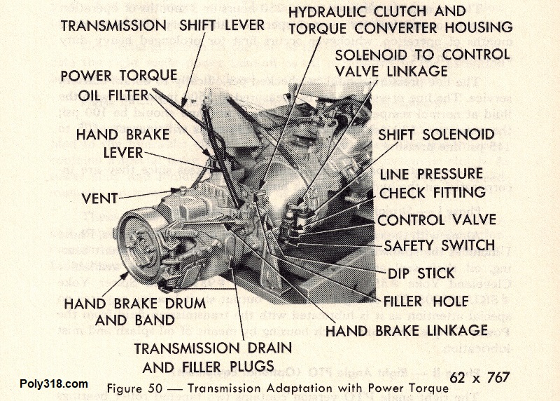
- Optional gearbox equipment included the “Power Torque” hydraulic clutch system for power take-off including the in-line PTO, right-angle PTO, and “several transmission adaptations covering tower and remote shift manual transmissions” (Figure 13b).
| Component | H318 and HB318 | HC318 | HT318 |
|---|---|---|---|
| HP Rating | 190 at 4,000 RPM | 190 at 4,000 RPM | 190 at 4,000 RPM |
| Compression Ratio | 8.25:1 | 8.25:1 | 8.25:1 |
| Compression Pressure at 150 RPM | 120 – 150 psi | 120 – 150 psi | 120 – 150 psi |
| Maximum Variation Between Cylinders | 20 psi | 20 psi | 20 psi |
| Oil Pressure at Idle (500 RPM) | 15 psi | 15 psi | 15 psi |
| Oil Pressure at 2,000 RPM | 45 – 65 | 45 – 65 | 45 – 65 |
| Oil Capacity (quarts) | 5 in pan, 6 with one filter, 7 with dual filters | 5 in pan, 6 with one filter, 7 with dual filters | 5 in pan, 6 with one filter, 7 with dual filters |
Conclusion
Poly A-block marine and industrial engines are a unique subsection that I hope to give more attention to on this page as I learn more from researching and from enthusiasts emailing me. Because of the low production numbers of vessels that used factory A-block engines, surviving vessels, engines, and parts are extremely rare. If you have information, vessels, parts, and/or photos, please email me so we may add to this body of knowledge to fill any gaps and preserve the information for future generations.