Poly 318 Cross Ram Induction


For the poly 390 stroker build for our 1956 Dodge coupe project, I wanted an induction setup that both compliments the larger displacement, larger valves, head porting, and hotter cam and that looks great sitting between the A-block valve covers and filling up the large engine bay. I hesitated writing this article because of the ego whispering of being the only A-block running around with this exact system, but I decided to share what I did since my whole purpose in building and maintaining this website is to contribute to the larger pool of A-block knowledge and to help fellow A-block hot rodders and stocker enthusiasts.
As a child, I remember being mesmerized staring into the engine compartment of a family friend’s 1961 Polara with its 413 long-ram induction and the sound it made. At cruise nights and weekly drag races, I was also drawn to the shorter 1962 – 1964 Max Wedge cross-ram setups. While the long-ram setup is excellent for low-end street performance, the longer runners impede performance above about 5,000 rpm on engines over 361 c.i.d., whereas the shorter 1962 – 1964 Max Wedge induction likes twisting to 6,500 rpm. Since Mopar never made a cross ram for the A-block and I want a shorter runner for the 390’s cam profile, enter Offenhauser 5497 cross-ram adapters. I contemplated building my own adapters or even a manifold out of aluminum sheet, but I want a more vintage cast look for the 1956 Dodge.
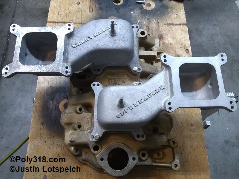
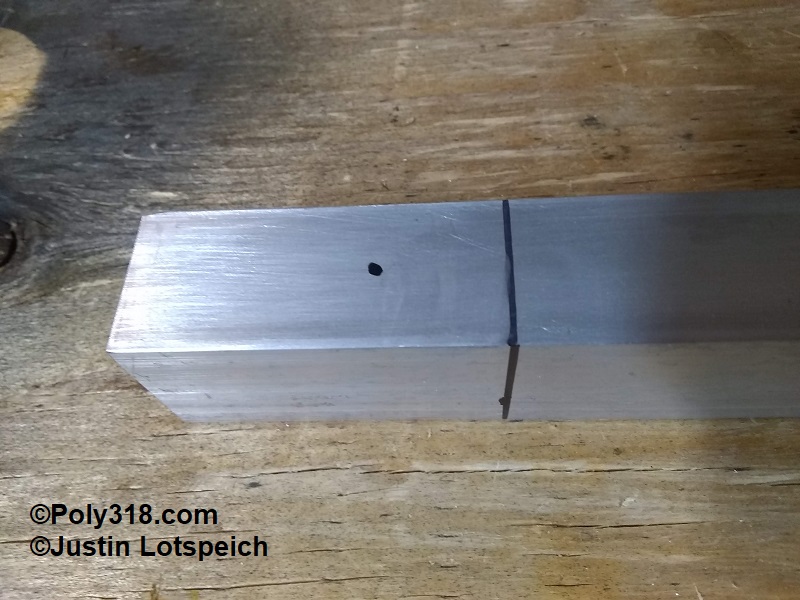
After a couple years of scrounging swap meets and online for a good deal since new cross-ram adapters are preposterously priced, I scored a lightly used pair (Figure 1). The next issue, and it was a major one, was the the throttle linkage system. Offy makes a bellcrank linkage system 5581 supposedly designed for dual 5497 adapters, so I started there, which turned out to be a mistake. At $200 for a couple bellcranks, towers, and rods, I decided to make my own. The cross-ram adapters I bought came with the crank towers, so I measured the cranks from Offy advertisement photos and built some out of 1/4″ Masonite for mockup before building them out of 1/4″ aluminum plate. I made the straight rods out of 5/16 rod with ball rod ends. After getting everything mocked up, I had a good laugh when the system looked and functioned like a fourth-grade science project focused on examining bellcrank mechanics. The first issue is that the Offy towers are aluminum with a 3/8″ base turned down to a wimpy 1/4″ shaft where the crank rides captured with a small cotter pin. Second, the Offy cranks don’t have the fulcrum point centered but instead offset where the rod connections are cantilevered badly away from the tower fulcrum. These two issues make the two cranks wonky, flopping all over the place up and down as I moved the gas-pedal rod back and forth. To make matters worse, the “L” and “T” crank legs are too short by about 2″ where the rods start at a severe angle to the carb throttle cranks and quickly bind pushing perpendicular to the rods and halting the system with the carbs only 1/4 open. I made up new rods with a 2″ “Z” in them to try and improve the geometry, but I was able to get just shy of 1/2 throttle with a ton of force on the pedal rod to where the 3/8″ aluminum crank towers began flexing sideways before everything bound up. I determined the Offy linkage design is garbage and utterly unusable.
Using the mockup rods I already made, I first made up different Masonite cranks that moved the fulcrum point to the center of the cranks and extending the rod points on the cranks out another 2″. This redesign worked a little better, but it still suffered from the cranks flopping up and down atop the Offy towers and was ugly since the cranks were now much larger and covered most of the cross-ram runners.
My third iteration happened on paper where I designed a flat bracket bolted from one crank tower hole to the other with a 3/8 grade-8 bolt tower sticking up in the middle of this bracket. There would be one single long “T” crank with a bearing pressed in to ride on the 3/8″ tower captured by jam nuts. The long leg of the crank would have the carb rod holes at each end with the short leg having the pedal rod hole. One carb would be a push and the other a pull. At least on paper drawing the arcs with a compass to mimic the bellcrank in action, this system appears to be practical, but it was ugly with a giant “T” crank covering most of the intake, and I suspect that even with a bearing on the 3/8″ shaft the “T” crank would try to flex up and down during use since the rod connections were so far away from the fulcrum.
At this point, I abandoned the bellcrank design and went to a combination of bellcrank and cables thanks in part to a conversation with my uncle who happened to stop by when I was playing around with designs. He explained that he used bellcranks a lot when he was once into model airplanes and initially suggested a bellcrank on the back of the intake that would convert the single pedal rod into two levers that would actuate one crank for each carb to keep the cranks smaller. Since I though that system would still present too many variables for slop and would still be ugly, I added my idea of a cable system to delete most of the bellcranks and rods. Thus, the final system design was born.
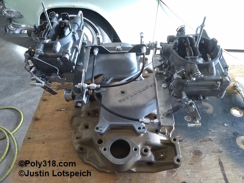
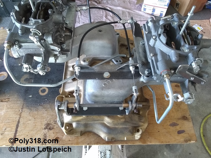
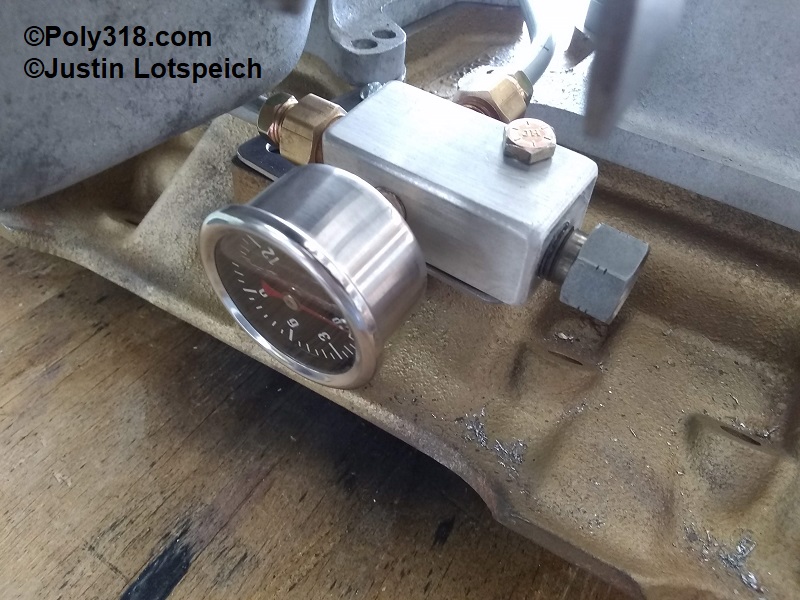
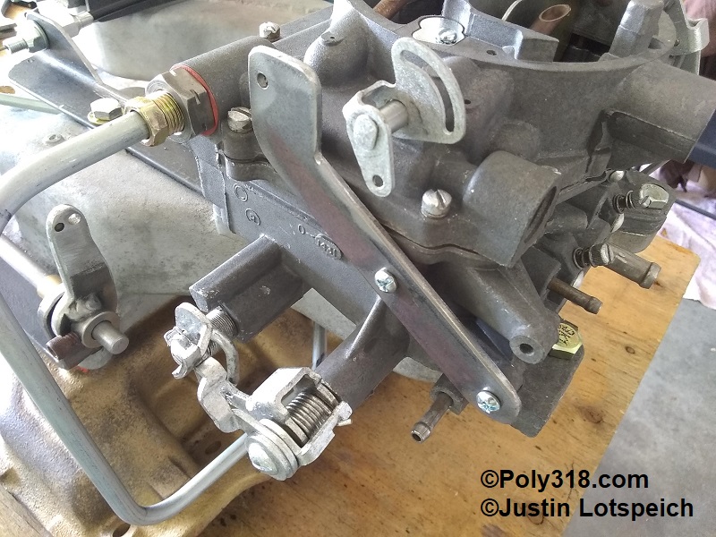
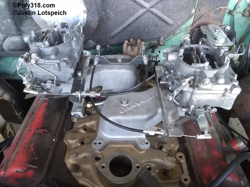
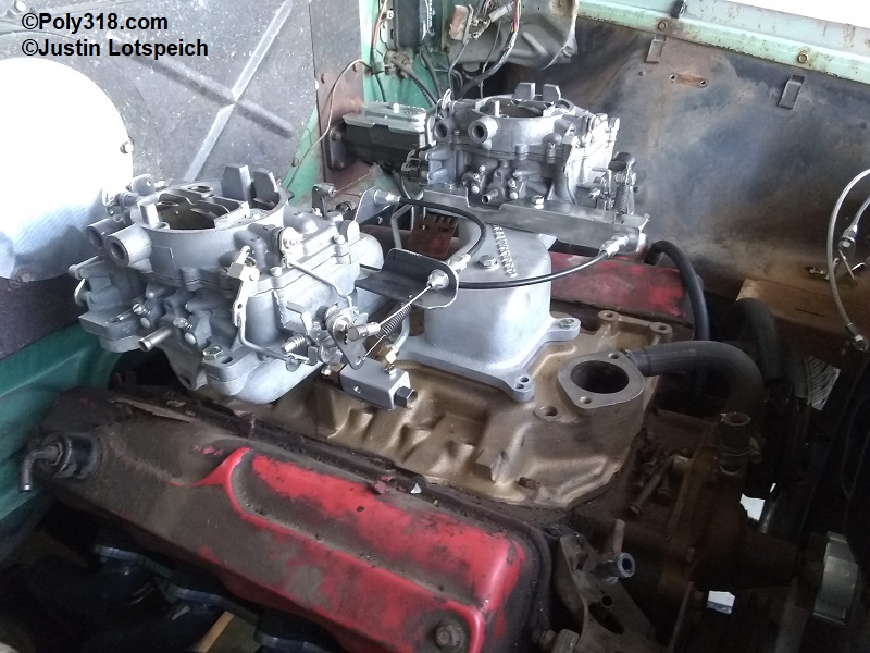
Playing around with carb positions, I settled on both carbs positioned with the throttle cranks forward to where one would be a pusher and the other a puller to give the cables a large enough radius to not bind or wear out the liner prematurely. I built brackets off the carbs to carry the cables and return springs and welded on a rear bracket to carry the other end of the cables, pedal return spring, and to serve as a possible mounting point for the ignition coil (Figure 2 and 3).
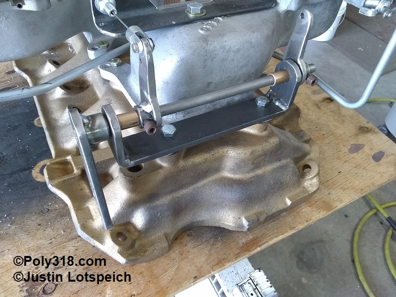
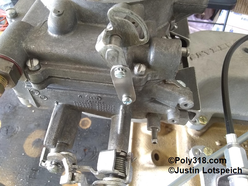
Wanting to build the bellcrank with no flex and to where it will hold up forever, I built a “U” bracket from 3/16″ flat bar and pressed in and peened 3/8″ bronze bushings. Next, I built the pedal crank from 3/16″ flat bar and rosette welded on the 3/8″ cold-rolled steel rod and a spacer to align the crank with the pedal crank in the 1956 Dodge. I built the two cable levers out of 3/16″ flat bar and welded on 3/8″ collars replacing their setscrews with 1/4″ Allen bolts so I could torque them down well (Figure 4). The 1956 Dodge gas pedal crank/rod actuates forward, so this bellcrank system converts the forward pedal rod movement to pulling back on the cables. The 1956 Dodge accelerator pedal setup includes another rod that goes down to actuate the transmission kickdown, so I will modify that system to actuate the poly 390’s 727 TorqueFlite’s kickdown (see my technical article on the performance transmission build). If I didn’t already have this system to work with, I would include a kickdown rod into the pedal bellcrank design or add a third cable lever and run an aftermarket kickdown cable.
The trick now was to match the pedal crank sweep with the carb throttle crank sweep. The 1956 Dodge accelerator pedal rod has a total of 1-3/4″ horizontal movement from full up to floored. Measuring in an arc at the factory rod-end hole of the throttle crank, the AFBs take 1-1/2″ sweep from closed to wide open. At first, to get optimal geometry of the cable in relationship to the sweep of the throttle crank on the rear carb, I built a 1/8″ plate extension bolted to the throttle crank to move the rod-end hole up 3/4″ from the factory position where the cable would pull down more versus horizontally. I built another extension to convert the forward carb from a pusher to a puller with the rod-end hole the same distance away from the center of the throttle shaft as the rear carb’s extension. Using cut-to-length cables, (not Lokar but great quality $24 units I found online), I mocked up the system to find that I had buggered the geometry by extending the carb crank fulcrums in hopes of getting better cable geometry. In order for the carbs to go wide open, I had to move the pedal crank nearly 3″ when it could only go a maximum of 1-3/4″. I built a new bolt-on crank extension for the rear carb to include a return spring and installed the cable rod end in the factory AFB hole. To help with the cable geometry, I bent the mounting bracket down and put in a slight twist so the cable sat pointing up a little. I was happy to get full throttle with 1-1/2″ of sweep at the pedal crank with no binding at the throttle crank. For the forward carb, I built a bolt-on crank extension to convert it from a pusher to a puller and to affix a return spring, placing the cable rod end the same distance away from the center of the throttle shaft to the center of the factory rod end hole. I twisted that mounting bracket slightly to point the cable slightly down to help with the geometry. After cutting and crimping the cables and fine-tuning the tension adjustments, I was able to get synchronized full throttle out of both carbs with 1-1/2″ of sweep on the pedal crank and smooth action. With the pedal crank and cable levers clocked where I wanted them, I filed flats in the 3/8″ rod to secure the cable levers and will use blue Locktite on the setscrews during final assembly after paint.
Using a piece of billet aluminum, drill press, and hand taps (if only I had a mill), I built a fuel block to convert the 3/8″ hard line coming from the pump to 5/16″ line to each carb with a fuel pressure gauge for diagnostics if ever needed (Figures 5 and 6). I built an 1/8″ plate bracket to mount the fuel block and to block off the factory choke exhaust well on the intake manifold keeping in mind I have blocked off the crossover and used an insulator washer under the fuel block where heat shouldn’t be an issue. From the fuel block, I made up the lines to each carb from a coil of 5/16 hard line and double inverted flare nuts, leaving space on the right side if I want to run the ignition coil underneath the rear ram adapter.
To address the choke system, I built a 1/8″ plate bracket off the rear carb that will secure a universal choke cable housing (Figure 7). On the forward carb, I built a sheet metal lockout tab (Figure 8). While I could file off the peened ends of the choke plate screws and remove the screws and plate, I want to keep both carbs complete until I know the system works well.
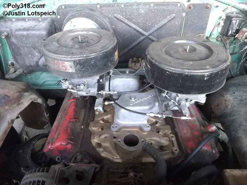
To crown the mill with a nod to both the 1958 Poly 318 “Dual Fury V-800” and the wedge long-ram and cross-ram systems, I installed two Slant 6 “Charger 225″ unsilenced air cleaners with aftermarket sheet metal bases I modified for the 4-7/32” AFB air horns (Figure 9 – 11). If my measurements are correct, keeping the A-block 390 stroker at the installed height of the Dodge poly 270 engine when I install the Dodge Dakota front clip, I’ll have just enough clearance of 1″ between the air cleaners and hood. I’ll be building captured polyurethane bushed motor mounts, so the engine shouldn’t rotate much to affect this clearance. I can increase the clearance by notching the air cleaner housings around the fuel inlets and running shorter filter elements, or I can try and lower the engine installed height and match the transmission crossmember accordingly. I will check off those variables when I get to them.
FIGURES