Classic Car Exhaust Systems
Mufflers
H and X Pipe Crossovers
Build Example
Introduction
This article is lengthy, but my hope is to assist others in better understanding the components of an exhaust system, some of the physics that should be considered when selecting components, and a practical application detailing my fabrication of an exhaust system for my 1956 Dodge coupe. While the later sections of this article focuses on my fabrication of an exhaust system for this car, the article applies to classic vehicle exhaust systems in general. There are a host of reasons why a vehicle may require a new exhaust system, from rotted out or damaged tubing, rotted out mufflers, a performance engine requiring larger diameter tubing and less-restrictive mufflers, for sound preference, etc. Most classic factory exhaust systems were designed for very low to mild-performance engines compared to what we are capable of building today. For stock engines, a stock exhaust system works just fine; for mild and high-performance engines, the factory exhaust system is usually restrictive and harms exhaust velocity. While I cover exhaust manifolds and headers in another article, this article focuses on rebuilding the exhaust system from the exhaust manifold/header collector flange back through the head pipes, mufflers, and tailpipes.
Exhaust Tubing Diameter
When designing a new exhaust system, we have multiple options for tubing and muffler diameter. Common available tubing diameters, measured as outside diameter, include 2″, 2.25″, 2.5″, 3,” although other sizes are available though less common. Big-chain auto parts stores and car magazines, whose main focus is selling products and advertising contracts, have since the 1990s pushed the idea that larger diameter exhaust is always better, period, no context needed. I often run across forum posts online where people ask for advice on exhaust tubing diameter for their stock 230 HP V8 where people respond in seriousness recommending 3″ exhaust because it will increase performance because it decreases restriction and back pressure–the same claims pushed by many magazines and product advertisements. What is left out of this assumption is the importance of maintaining exhaust velocity to evacuate the system as quickly as possible while not creating excessive back-pressure. In reality, proven by many dyno results and track times in multiple credible publications, 3″ exhaust on a stock 230 HP V8 will decrease performance compared to, say, a 2″ diameter tube because it kills velocity throughout the entire rpm range of the engine since that engine cannot flow enough air to maintain velocity in a cavernous 3″ tube. An engine requires a certain about of exhaust restriction that by nature produces back-pressure to function at optimal performance. On the other end of this example, putting a 2″ diameter system on a 500 HP engine will create high velocity but accessive back pressure and decreases the volume of air the engine can pump. For people not a trained exhaust engineers and who don’t own a dyno or have the many thousands of dollars to build multiple systems and run multiple days of testing, designing a suitable system comes down to using available averages and find a balance of all the variables focused around a specific engine’s intended use.
So what are the established averages for optimal exhaust tubing diameter? I’ve reviewed and averaged out the recommendations from leading exhaust-system designers and retailers for naturally aspirated engines with dual exhaust. These ranges should be used as starting points for designing a system since other variables may require a smaller or larger diameter tube. For example, engines that benefit from lower-rpm torque–such as launching from a starting line or off-roading–benefit from smaller diameter tubing but at the cost of higher-rpm performance. Another considertin is that Engines with blowers, superchargers, or tubros often benefit from larger diameter tubing. I neglect engines over 800 HP since they likely will be serious racers who spend the money on having a system designed through testing since the difference in the exhaust can mean the difference between winning a race purse or losing.
- Below 250 HP: 2″
- 250 – 350 HP: 2.25″
- 351 – 500 HP: 2.5″
- 501 – 800 HP: 3″
Tubing Gauge and Material
Another consideration of the system is the tubing gauge and materials. Common exhaust tubing gauges for the head pipe back are 14 and 16 gauge, 14 being thicker than 16. Within reason, heavier gauge tubing is superior to lighter gauge because it allows cleaner bends with fewer kinks and other corrugations that impact flow; it allows for cleaner, stronger welds; it maintains higher internal gas temperature that assist with velocity; and it sustains more corrosion before it rots out. I use 14 gauge for the head pipe back.
Tubing material often comes down to aesthetics and the method of joining the system:
- Aluminized Steel: Mild-steel tubing with an aluminum coating. This is the exhaust tubing I use because it is affordable, bends nicely, holds up well to exterior corrosion, and welds nicely with argon MIG. The welds require paint or they will corrode.
- Galvanized Steel: Mild-steel tubing with a galvanized coating. There’s nothing wrong with this material, and it was what manufacturers used on our classic cars and some still use today. Note that welding zinc puts off some nasty poisonous fumes that require a good fan flow and ideally a respirator. The welds require paint or they will corrode.
- Stainless Steel: It is the most corrosion-resistant material but is the most expensive and requires either MIG set up with stainless wire or TIG. Note that stainless steel exhaust tubing can be welded with mild-steel argon MIG, but the bead is obviously mild steel and will corrode without paint.
Type of Bends
There are two methods shops and suppliers use to bend exhaust tubing:
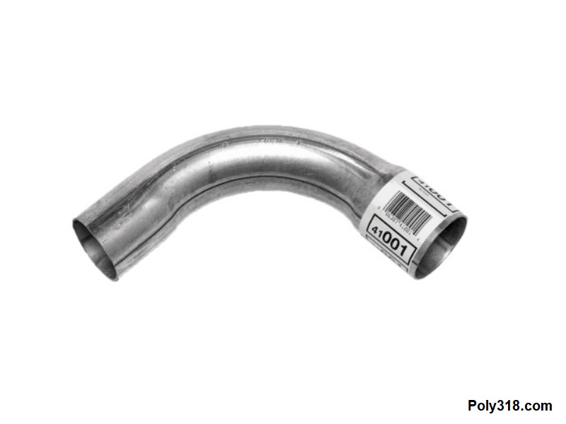
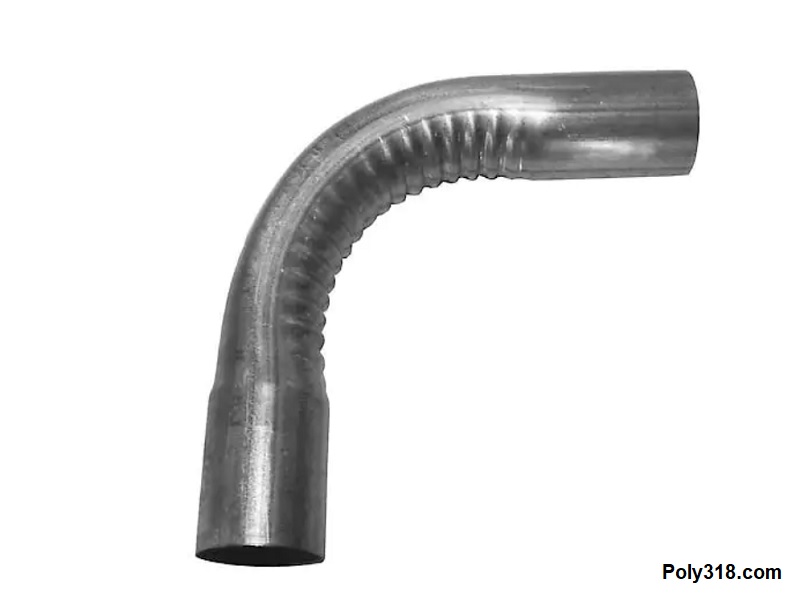
- Crush Bending: This method is the oldest and cheapest way to bend exhaust tubing and is similar to how electricians bend EMT electrical conduit. It uses a set of dies that surround the outside of the tubing to stop it from crushing too much during the bending. The resulting bend has a reduced diameter (Figure 1a) and can have series of corrugation on the short turn of the bend (Figure 1b) since the inside of the tubing is not supported and must crush inward to decrease the length on the short turn of the bend while the long turn of the bend remains the same length or stretches slightly. For stock or low-performance engines, crush bending is perfectly fine, but for high-performance engines the inconsistent diameter and corrugation create issues with equalized flow.
- Mandrel Bending: This method is more expensive than crush bending but has benefits worth the extra cost. The bender uses a set of dies that tightly surround the outside of the tubing to stop it from crushing during bending and includes a series of steel balls/disks that are dragged through the inside of the tubing during bending to stretch the tubing into shape to maintain a more consistent, smoother diameter (Figure 1c). The resulting bend has no or very little reduction in diameter and no corrugation. Mandrel bending for performance reasons is overkill on stock and low-performance engines since the gains are minimal compared to other engine upgrades. Mandrel bending for mild and high-performance engines is worth the additional cost. Mandrel bending is also aesthetically more pleasing, in my subjective opinion, since it looks uniform.
Types of Connections
There are four types of exhaust connections that may have varying designs:
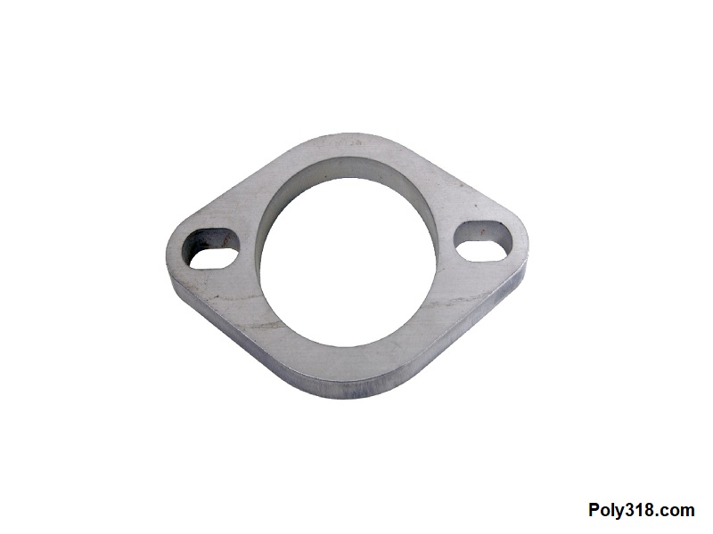
- Flat Bolt-through flange: The most common form of this connection is from an exhaust manifold or header collector to the head pipe (Figures 2a – 2b).
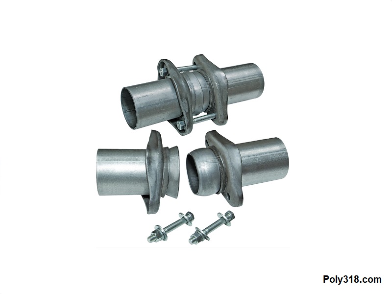
- Ball Flange: A connection becoming more popular that uses a ball and socket to form the seal (Figure 2c). This connection allows some angle adjustment in the connection compared to the flat flanges that once welded must maintain their angle.
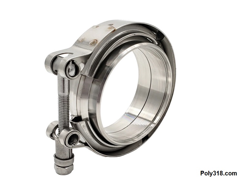
- Compression V-band clamp: This type of connector is more common on newer vehicles and uses a heavy strap to lock in the two sections that both have a slip that the clamp grips (Figure 2d).
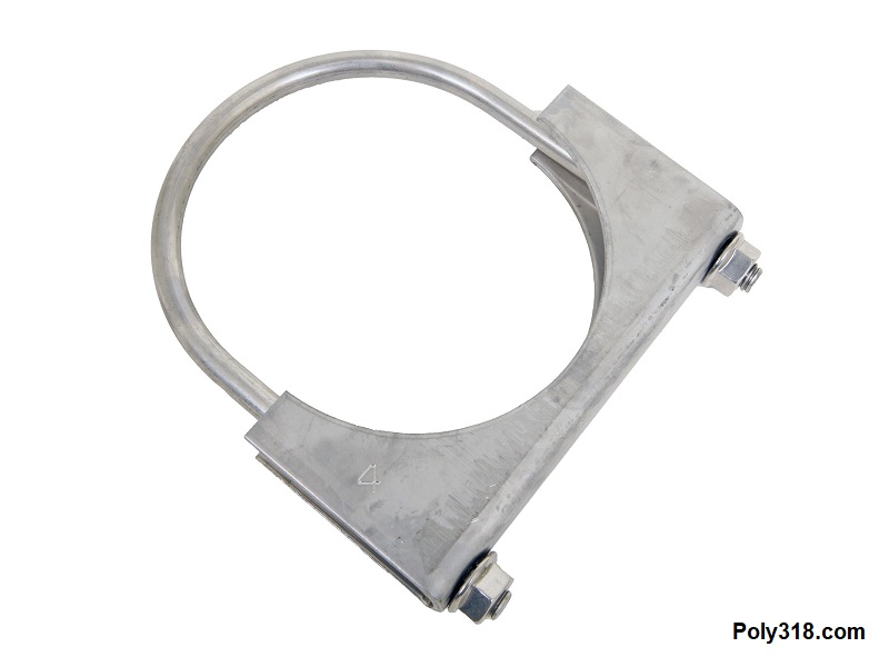
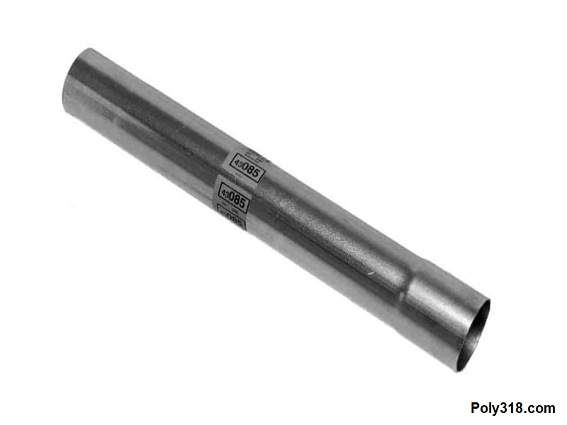
- U-bolt Clamp: This is the most common connector included in DIY kits, although some exhaust shops use them for connections. They can also be used for attaching exhaust hangers, which I cover in the next section. They include a threaded u-bolt and a strap (Figure 2e). There is a flared female socket at the end of one tube (Figure 2f). When the clamp is bolted down tightly, the female socket crimps down onto the male tube creating the seal. While this type of connection works in general, it usually produces some slight leaks, depending on how well the female socket and male tube fit, and can rotate with vibration if the exhaust is not supported well with hangers. One benefit of u-bolt connections is that the exhaust can be put together with hand tools, although a connection crushed tight enough to stop leaks are difficult to disassemble.
- Welding: This is the cleanest and strongest connection. Not all connections should be welded, such as the manifold/header to head pipe, but most can be welded. The welds seal the tubing and stop the connections from rotating. When I began welding exhaust in my early teens before I could afford a MIG, I used oxy-acetylene torch, which can produce a nice bead but burns off more coating than MIG and TIG. I now weld exhaust using argon MIG since it is the quickest weld and produces a clean weld. Flux-core MIG can be used if the amperage and wire speed is dialed in really well since it will create excessive spatter and blowout otherwise. TIG is the cleanest exhaust weld but is a much slower process. I don’t recommend attempting to weld exhaust tubing with an arc welder due to the high heat and resulting blowout.

Exhaust Hanger Options
A properly designed exhaust system includes a series of hangers that secure the system from excessive movement and holds the hot components away from sensitive areas. Hangers should incorporate some type of shock absorber to both stop vibrations from entering the cabin and to stop either end of the hanger connection from breaking due to metal fatigue due to engine and suspension movement/vibration. The following list are the most common types of hangers, although other designs are available.
- Clamped with Strap (Figure 3a): This hanger is one of the cheapest in price and most common in prefabricated kits. The hanger bolts to the chassis/body and uses a u-bolt like Figure 2e above to secure it to the tube. The strap is not the heaviest gauge and can easily bend in my experience, which may or may not be advantageous.
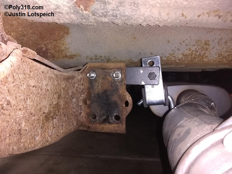
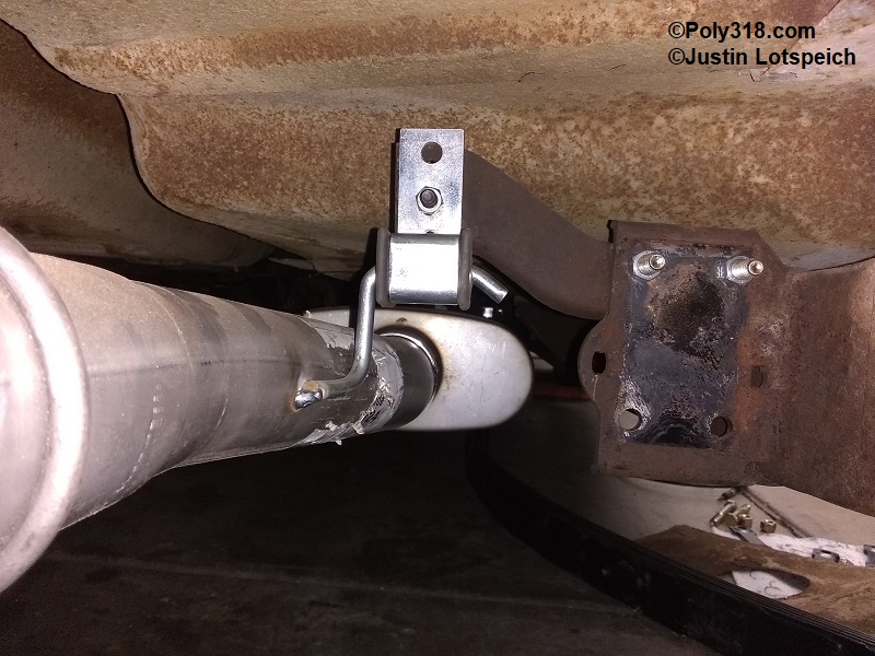
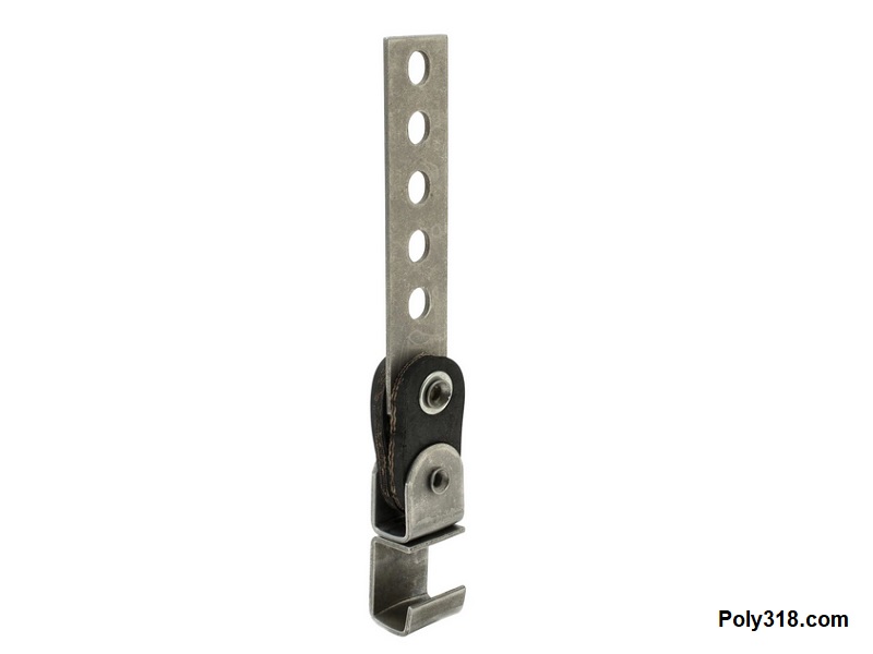
- Welded with Rubber Damper (Figure 3b): This hanger has become my go-to. It includes a heavy stainless steel damper housing and captured rubber damper that bolts to the chassis. A hardened 3/8″ stainless steel rod welds to the exhaust tube and slips into the rubber damper. This hanger provides excellent vibration dampening, looks clean, and allows the exhaust to be removed without the need of tools by rotating the rod and sliding it out of the damper.
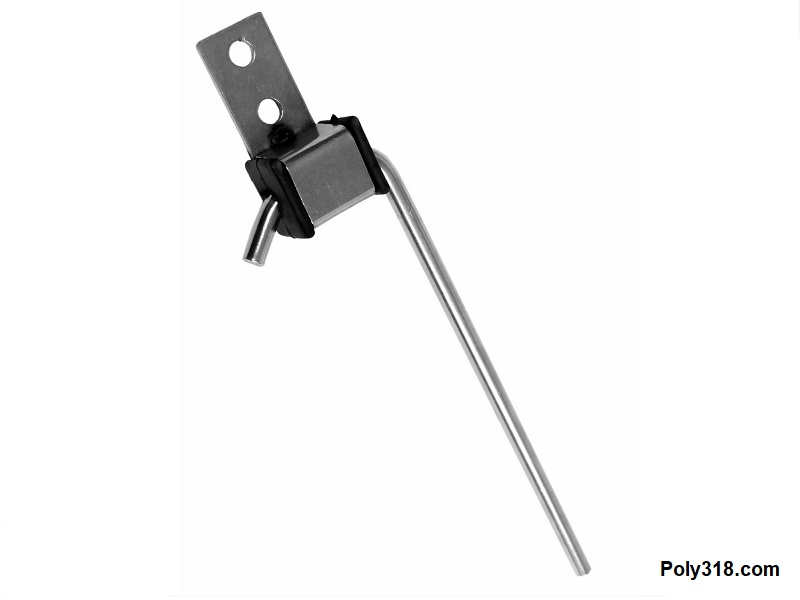
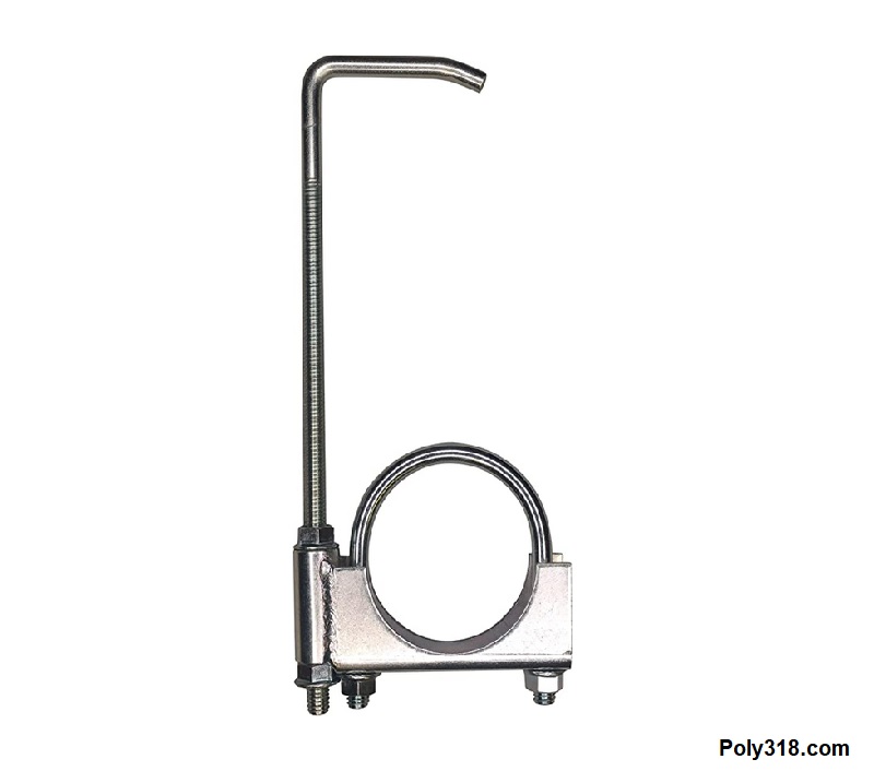
- Clamped with Rubber Damper (Figure 3c): This hanger uses the same damper housing and damper as the previous hanger. The difference is that rather than welding to the tube, the rod is threaded and bolts through a u-bolt that clamps onto the tube.
Muffler Options
I wanted to cover common muffler options, terminology, and restriction designs important to consider when designing a system. There are dozens of muffler models available to suite any system.
Inlet and Outlet Configuration:
- center in, center out
- offset in, center out
- offset in, offset out
- offset in, center out
- single inlet, single outlet
- single inlet, dual outlet
- Dual inlet, single outlet
- Dual inlet, dual outlet
Flow Direction: Mufflers can either be directional flow or reversible, as in either end can be used as the inlet or outlet. Typically, mufflers that have straight-through design with no walls can be reversed.
Housing Material: Common mufflers come in different materials similar to the exhaust tubing including galvanized steel, aluminized steel, and stainless steel.
Internal Design:
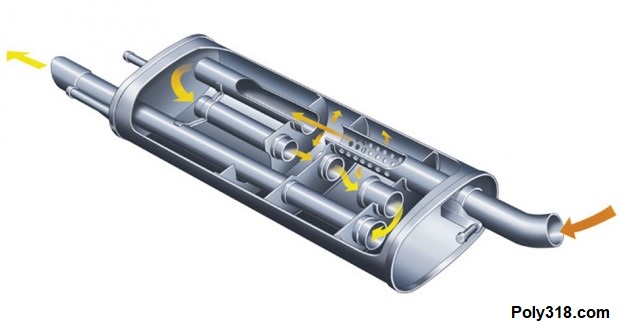
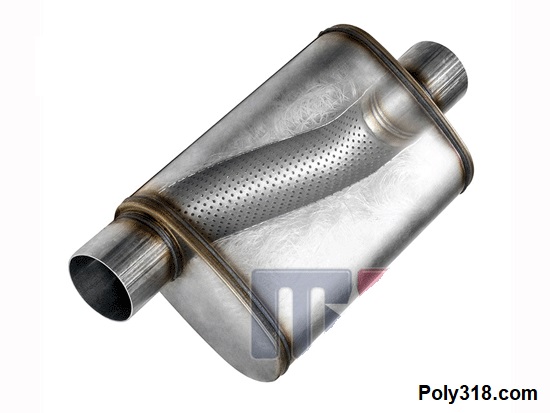
- Factory (Figure 3a): Factory mufflers include perforated internal tubes, and some have different compartments to muffle noise. The housings are stamped and crimped usually made of thin-gauge galvanized or aluminized steel sheet. The muffler is more concerned with noise suppression than performance and restrictive to velocity.
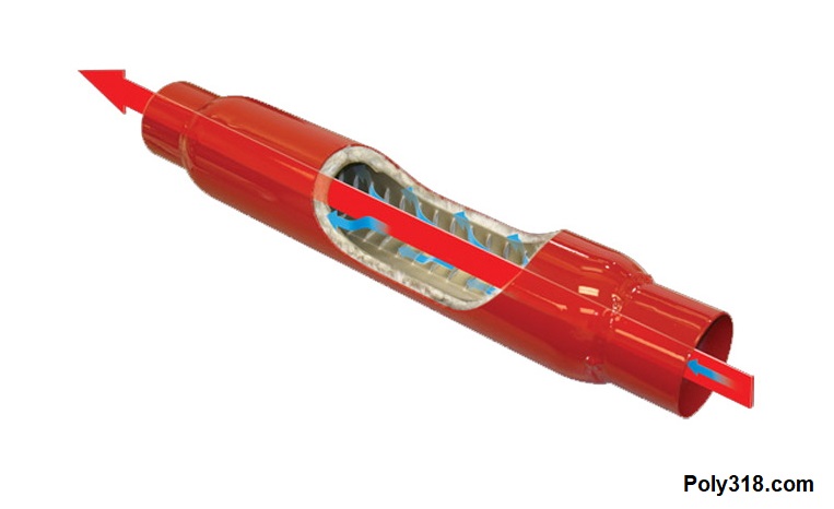
- Traditional Glasspack (Figure 3b): This type of muffler was one of the first “performance” mufflers developed. The housing is commonly a long, heavy gauge tube that uses a straight perforated tube through the center that is surrounded by fiberglass packing–hence the name “glasspack.” Some models use a larger rectangular housing. With heat, acidic gasses, and air flow, the fiberglass packing eventually deteriorates and blows out decreasing resistance and increasing the noise volume since the muffler then acts more like a straight pipe with little noise suppression. The muffler can usually be reversed.
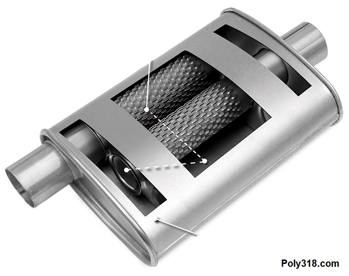
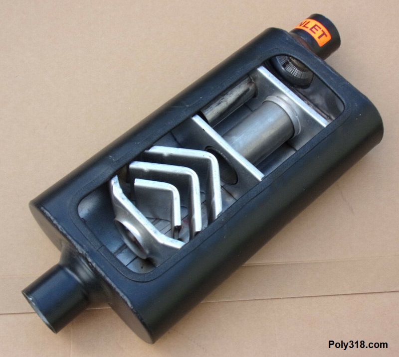
- Turbo (Figure 3c): Another early performance muffler still popular today, the turbo muffler has a series of perforated tubes and walls that provide less resistance and noise suppression than a factory muffler but more restriction and noise suppression than most chambered mufflers. Some models have the perforated tubes wrapped in fiberglass or steel fiber to manipulate the tone and volume. Many of the housings are made of stamped steel sheet with crimped joints similar to a factory muffler, and some are made of heavy gauge steel sheet with welded joints.
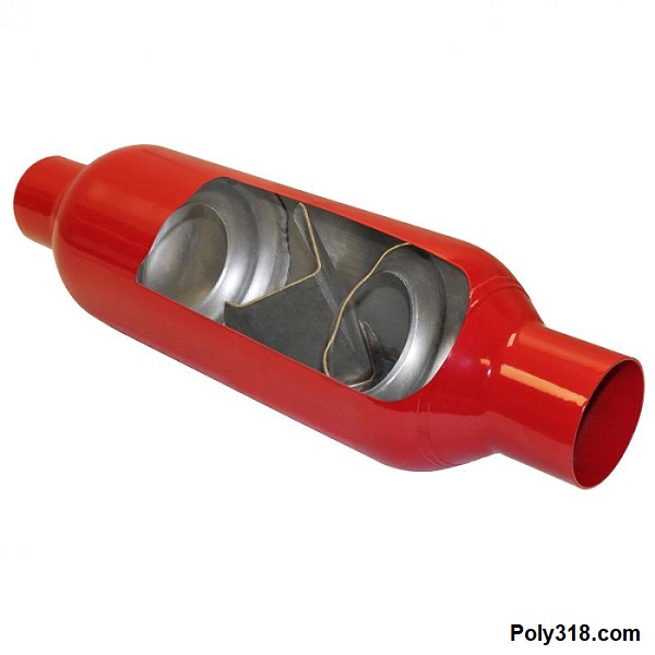
- Hybrid Glasspack-Turbo (Figure 3d): This performance muffler is a hybrid of the glasspack and turbo mufflers. It has a single perforated tube running through the housing at the same diameter as the inlet and outlet. It typically uses a heavy gauge rectangular housing with welded joints like most chambered mufflers. Rather than fiberglass, the perforated tube is surrounded in a stainless steel fiber to manipulate the restriction and noise suppression. The muffler provides less restriction and noise suppression than turbo mufflers. The stainless steel packing does not deteriorate like fiberglass, so the resistance, noise suppression, and tone remains consistent.
- Chambered (Figure 3e – 3f): This performance muffler has less restriction and noise suppression than the other mufflers and includes a series of walls and passages. It can include a single chamber or multiple chambers. The short single-chamber design is the least restrictive and noise suppressive and was designed for racing classes at tracks where the local city ordinances and, therefore, track rules require a muffler, although they don’t do much noise reduction.
Balancing Crossover (H Pipe and X Pipe)
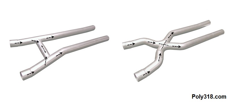
The final consideration I want to include here is a balancing crossover. A length of tube connects the two separate tubes on a dual-exhaust system in either an “H” or “X” formation (Figure 4). Similar to exhaust tubing diameter, there is a lot of misinformation online about the benefits and necessity of having a crossover. First, an exhaust system on our classic vehicles does not require a crossover to perform well. Adding a crossover has some attractive benefits including cabin resonance, engine performance, and exhaust tone, but, as with anything, context is key just like the discussion of tube diameter. The context is complicated, so I do my best to summarize here.
The Reasoning behind a Balancing Crossover and How it Works:
Through the design of V8 engines, each bank of cylinders functions in a sequence offset from and independent of the other bank. The banks alternate the firing of each cylinder, so while one bank is firing, the other is not. This necessary design produces different exhaust dynamics. These unequal pulses running down the exhaust legs impact engine performance to a very small extent but can and often have a major impact on noise resonance in the cabin, especially if the engine’s camshaft has longer duration. If you have ever been in a classic vehicle that while cruising down the road at a sustained engine speed has an annoying, loud drone, it is likely the resonance from the unequal exhaust dynamics. A crossover usually removes this drone, which is the main benefit of a crossover for the vast majority of classic vehicles. The crossover works by allowing the two banks of exhaust to mix together and equalize to a large degree early in the head pipe that creates a more equalized pulse down the rest of each leg and supports exhaust gas velocity both in the legs and back into the engine.
Debunking the Misinformation about Crossover Power Gains:
The misinformation pushed by aftermarket manufacturers and their affiliated magazines that overflows into online forums is that a crossover provides significant performance gains, which is not true. A crossover has very little performance impact on the majority of street and amateur strip vehicles. There are very slight differences in performance between an H and X crossover, but they are so subtle I’m not going to go into them here since only the most serious professional racers would benefit from the difference. Averaging published dyno results show that a crossover placed using a dyno for optimal location may add up to around 15 HP and torque to a high-performance engine putting out 500+ numbers, and it adds closer to 5 HP and torque in stock or milder builds under 400 numbers. Looking at the part on a cost-benefit basis, if the vehicle’s owner does all the fabrication and has to purchase the materials in small quantities, a removable “H” crossover made of mild steel (not stainless) will cost about $60 in tubing, four flanges, gaskets, and bolts/nuts after taxes plus shipping. Prefabricated clamp-on mild-steel kits cost upwards of $100 after tax. Let’s assume this person isn’t going to spend $500 or more for a day of dyno testing to place the crossover, so the guess at location might add 10 points at the most. For a 500 HP or torque engine that may pick up 10 points, the $60 investment comes out to $6 per point. If the engine puts out 350 HP and may see an increase of 5 points, the $60 investment comes out to $12 per point. Both of these numbers at face value are a cheap dollar-to-power ratio, but neither the 5 points nor the 10 points will be at all noticeable in the seat. If, like most people, the vehicle owner cannot fabricate the crossover, I suspect an exhaust shop would charge at least $250 for a drop-out “H” crossover based off 2 hours labor and material markup and tax. A fixed crossover (as in no drop-out) would be cheaper in labor and materials by about 1/3 I’d expect. If the job cost $250, the 350 HP engine would now be $50 per point and the 500 HP engine $25 per point. These costs go up much more for an “X” crossover since it requires more labor and materials. Depending on the vehicle’s weight, the 350 HP engine with a 5-point bump might pick up 1/20th of a second in the 1/4 mile on a good day, if that. Since the faster the same weight vehicle goes the more power it takes to go faster, the 500 HP vehicle with a 10-point bump may see about the same gains in the 1/4 mile even though the crossover adds twice the points. I’m not going to do all the math to figure out the exact gains, but they are so minimal a gust of wind while going down the track would scrub them away. For professional racing where every fraction of power is needed to win a race with thousands of dollars in the purse, there is a strong argument for installing a crossover. For a street or amateur strip vehicle, the argument for a crossover for performance reasons fails. The hands-down strongest argument for a crossover on a street or amateur strip vehicle is the significant decrease in cabin drone–which is easily worth $60 – $250 to me.
Exhaust Tone of the “H” versus the “X” Crossover:
Briefly, without going into the physics that produces the difference in exhaust pitch, the “H” crossover produces a lower exhaust note associated with traditional American hot rods, whereas the “X” crossover produces a higher note associated with modern import and sports cars. For my personal preference, I prefer the sound of an “H” crossover compared to an “X.”
Crossover Placement and Tubing Diameter:
If you choose to include a crossover, which I do to remove or greatly decrease cabin drone, you may as well place it for the best audio and performance gains within reason without having a dyno to locate the optimal location. Although moving the crossover forward or back and increasing or decreasing the width of the crossover changes the dynamics detected by a dyno, the range from all the exhaust designers I’ve averaged is between 8″ and 20″ behind the beginning of the head pipe (as in the collector flange). If transmission, drive shaft, and/or muffler obstructions force you to place the crossover closer than 8″ to the head pipe start or farther back than 20″, it’s not a deal-breaker since there will still be benefits in decreasing cabin drone. The crossover tubing diameter should not be smaller than the head pipes and does not need to be larger.
Putting the above Details into Practice on 1955 – 1956 Dodge and Plymouth Vehicles
To give a practical example of designing and fabricating an exhaust system, I’ll go through the work I did on my 1956 Dodge coupe. While I don’t profess to know all the available exhaust kits for these cars, there are limited prefabricated kits for those who want to do the installation themselves, particularly for larger-diameter systems for high-performance engines. There may be kits that fit well, so please email me if you have personally used a good kit so I may include the information. Of course, a quality exhaust shop can bend up and install an exhaust system for our cars, but prices for this service have greatly risen commensurate with labor rates and material costs. Since I prefer to do my own work, I was faced with finding the best prefabricated bends at an economical enough cost to make doing the work myself worthwhile.
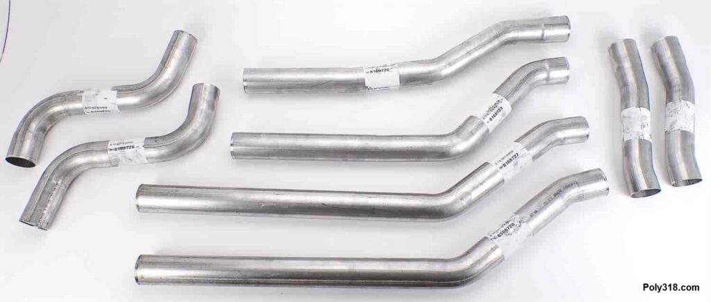
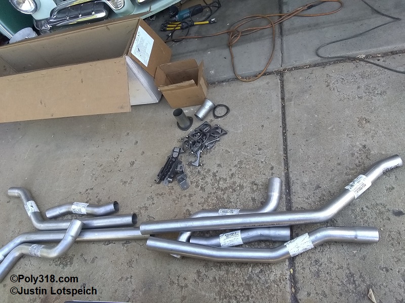
Parts Selection:
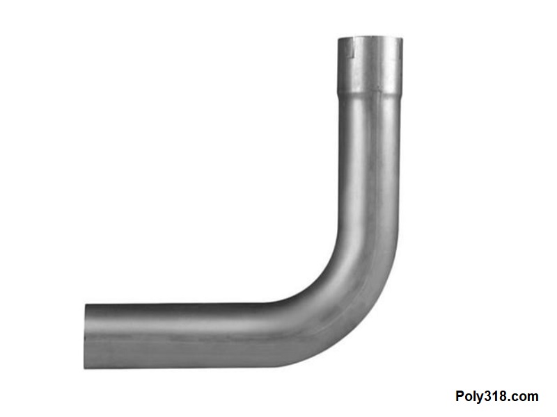
I wanted mandrel bends, 14-gauge mild steel, 2.5″ diameter, but purchasing enough individual bends, straight sticks, and collector reducers and flanges added up to an unreasonable cost for a self-designed system, so I researched available universal and model-specific kits for classic cars across all brands. After evaluating the options available, I chose a 1968 – 1974 Mopar B-body 2.5″ diameter kit from JEGS, #30503 for $370 after tax shipped as of 2022 (Figure 5a – 5b). The tubing was quality 14-gauge aluminized steel and welded well with argon MIG well. The female sockets were well-formed and not too oversized beyond light peening. The mandrel bends were well-formed with no crushing. I purchased an additional 8′ of straight tubing for the head pipes rather than using the provided offset head pipes due to the position of the headers I built. The provided bends also allowed me to properly route up over the rear axle and correct what I find is an inconvenience in the factory routing that runs too tightly under the gas tank and makes removal and instillation more complicated than it needs to be.
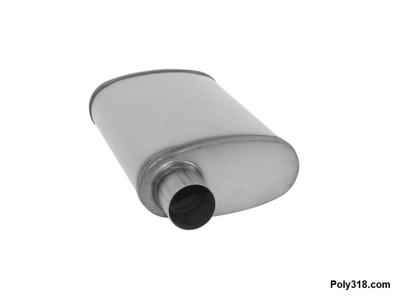
For mufflers, I chose 2.5″ Cherry Bomb “Salute,” which is a turbo-glasspack hybrid with an offset inlet and center outlet, although the muffler is reversible in direction (Figure 5c). I went with the Salute after hearing them idling in the pits and going down the 1/4-mile track and liking how they have a slightly deeper classic tone than a turbo and a volume about halfway between a turbo (a little too quiet to me) and a dual-chamber muffler (louder than I want on longer street cruises and for my neighbors to put up with in the early morning or late at night). The muffler was well built from heavy gauge stainless steel and welded joints, and it produced clean welds to the aluminized steel tubing with argon MIG.
Note that in some of the following photos, I show the exhaust clamped with u-bolt clamps and tack welds, but the finished system is fully welded with no u-bolt clamps. I use the clamps during fabrication to crimp the female sockets just enough to hold the tubes in place as I manipulate their positions. I use rebar tie-wire to raise/lower the tubing, pull the components toward/away from the chassis and components, and to hold the mufflers level from rotating. To maintain tight clearances, I use a combination of wood blocks or rags to hold the tubing away from the object during tack-welding.
Construction:
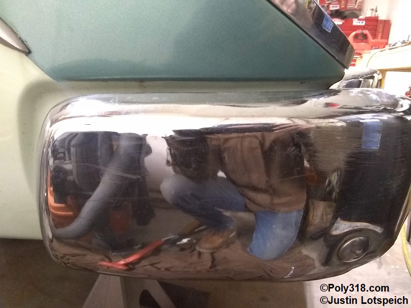
Before beginning the system design and construction, I had to address the rear bumper. Taking the time to dial in the bumper is crucial since a bumper out of adjustment will result in incorrect tailpipe and tip placement. I carefully measured and adjusted the bumper to ensure both sides were located evenly away from the fins (Figure 5d), even in elevation from top of fin down, centered from side to side, and that the wrap-arounds were located just under the recess in the quarter panel (3/8″ down in my case) and parallel to the recess line (Figure 5e). Likely from the factory since I found no sign of damage or bent brackets and I’ve already confirmed the chassis is not diamond when I built the Dakota front clip, one side of my bumper was 3/8″ too far out at its adjustment limits. I had to remove that side’s bracket and elongate the three holes in the frame rail to allow the bracket to slide 3/8″ farther forward to both match the other side and to close the visible gap between the bumper and valence. I used 1956 photographs to determine where all the bumper lines rested from the factory. If I had not taken the time to adjusted the bumper and built the tailpipes and tips around it, when I adjusted the bumper during body work before paint one tip would be 3/8″ longer than the other–a noticeable issue with such tight clearances to the bumper.
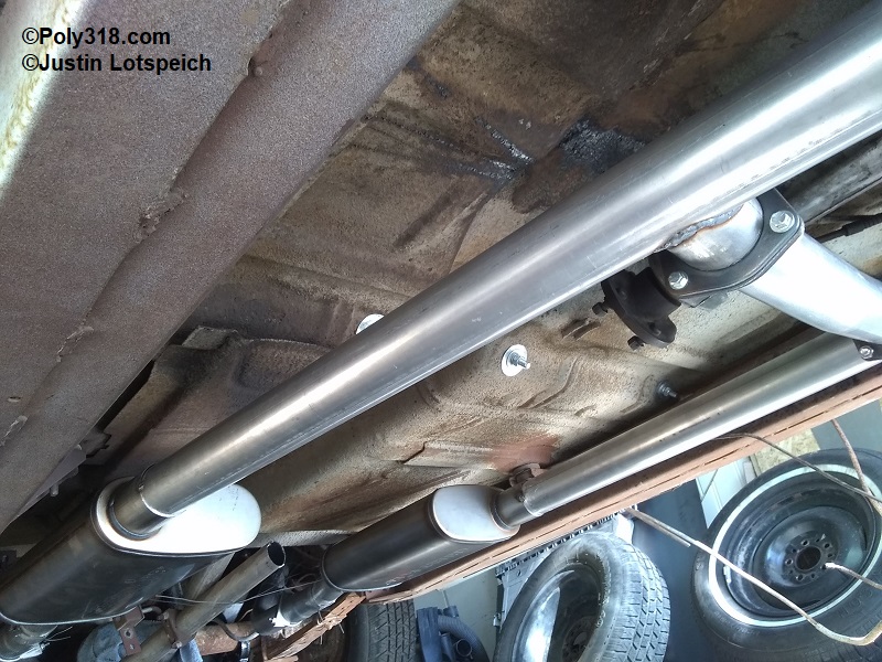
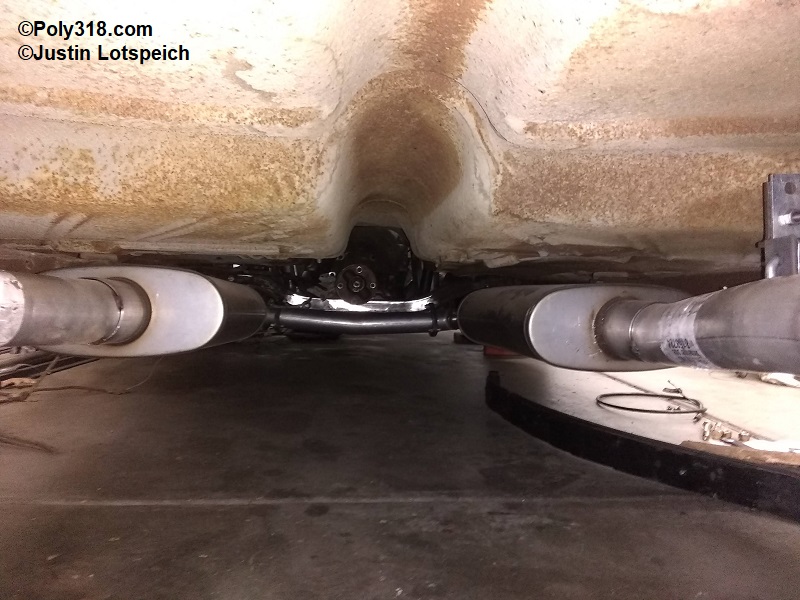
Coming out of the 3″ header collectors, I used the reducers included in the JEGS kit. I cut the head pipe and reducer butt-joint at a slight angle to point the head pipe toward the muffler inlet. I ran the head pipes into the mufflers with the inlets positioned toward their respective frame rails (Figure 5f). I will build and cut in the “H” crossover at a later time, which I detail in the next section. I played with the elevation of the mufflers to where they were not visible from viewing the car from the side but were low enough to keep excessive heat and noise out of the cabin. Running the head pipes straight back with the muffler inlets toward the frame rails placed the mufflers and tubes away from the drive shaft, close to the factory locations, and positioned where the parking-brake cable had enough room to clear between the muffler and frame rail.
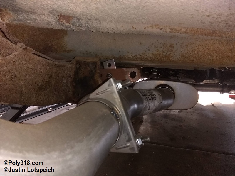
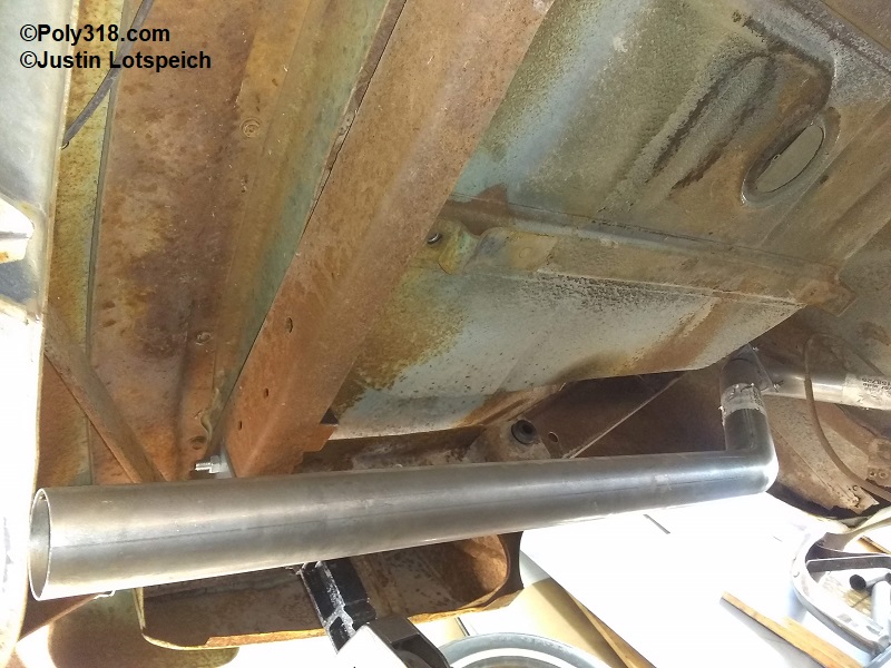
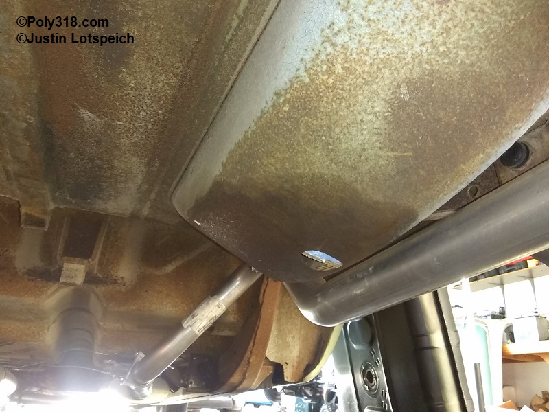
Coming out of the left (driver) muffler, I used the short jog with the most offset (far right in Figure 5a) to move toward the left frame rail, followed by the pre-axle “S” bend marked “driver side,” and the tailpipe marked “driver side” (Figures 5g – 5i). In routing over the axle to clear the shock absorber, gas tank, and to provide ample clearance above the axle housing, I had to removed the left axle bumper bolted to the bottom of the chassis and rotate the tubes in a way that placed the hump’s apex just under the frame rail but not hanging out past the outside of the rail where it would interfere with a wide tire. A reader may think that removing the axle bumper and placing the exhaust in its place is a bad idea, but I checked that even with the most extreme amount of passenger load and bouncing the rear bumper, there is 10″ of clearance between the top of the axle and the bottom of the exhaust tube, and the inner body wheel well bottoms out on the tire with 6″ clearance left between the axle and exhaust tube. With no threat of making contact, the rubber bumper is useless since the chassis and exhaust is in no danger of making contact with the axle.
With the tailpipe routed this way, I was able to bring it out the back straight/parallel with the body, between the gas tank side and leaf spring, and aesthetically pleasing up close to the bottom of the bumper. This routing also provided more room between the gas tank and the exhaust to make tank installation/removal much easier than with the factory routing since to remove/install the tank off of the filler neck requires pushing the tank toward the left side. Something to keep in mind is that the clearance in this area is tight with 1/4″ between the tubing and the left-front side seam flange of the gas tank and 1/2″ between the side of the leaf spring shackle bolt. While this is enough clearance since I secured the exhaust well with hangers, I took the precaution of bending up a 2″ section of the gas tank seam like the factory did at the hold-down straps, which gave me 1/2″ total clearance. By the time the exhaust reaches this area, the tube is only warm to the touch with no danger of a fire hazard. The leaf spring under heavy bouncing clears the tube, but a very slight dimpling of the tube if I find rubbing after test driving will resolve any rubbing and not impact performance being at the very end of the run.
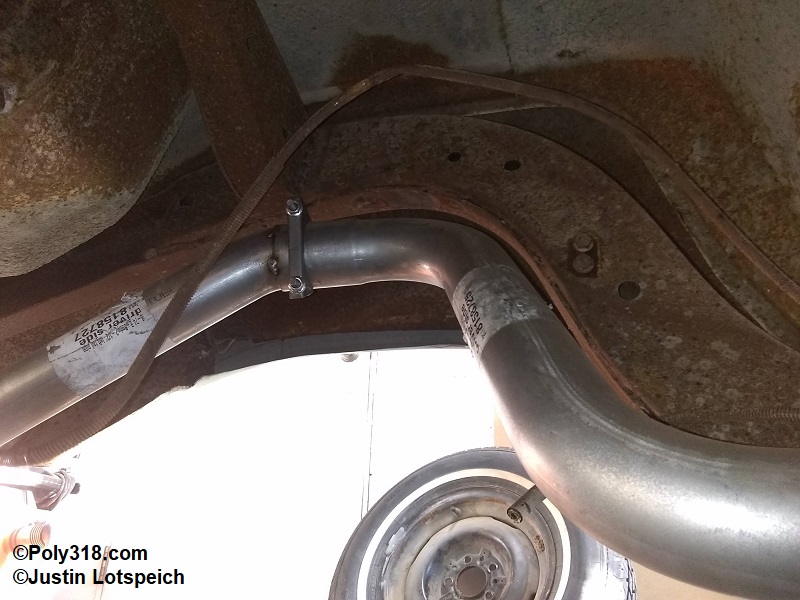
For the right (passenger) side coming out of the muffler, I used the short jog with the least offset to move the tube away from the right frame rail, followed by the pre-axle “S” bend marked “passenger side,” and the tailpipe marked “passenger side” (Figures 5j – 5l). I rotated the tubes to where the apex of the hump over the axle rested below the frame rail similar to the left side but farther inside. I will abandon the chassis rubber bumper on the right side as well since it isn’t needed. This position placed the tailpipe on the outside of the spare-tire well, parallel with the body and left tailpipe, and evenly located off the center of the body equal to the left tailpipe. Placing the tailpipe outlets took a lot of trial and error to get the correct location with a slope that looked good when viewing the car from the side and rear. After I triple-checked all the system’s clearances and positioning, I placed four tack-welds on each of the joints from the muffler outlet back to hold everything in place but left the head pipes loose to fabricate the “H” crossover, which I detail in the next section. Figure 5m shows the two legs completed.
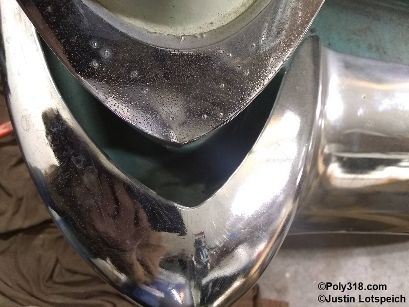
Tailpipe Decorative Tip:
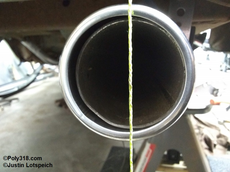
For the 1955 – 1956 Dodge and Plymouth with a gloss paint job, I prefer round polished tips with a rolled edge and that are stainless steel to resist corrosion from exhaust water and acids. In the 1950s, Mopar offered an attractive oval tip with vertical bars, but reproduction tips in this style drastically reduce the square inches below the 4.40 square inches of the 2.5″ tubing. The round tip slides over the outside of the exhaust tube and is welded in place around the perimeter of the front (toward the engine) of the sleeve. One thing that bothers me aesthetically is when people simply slide these tips onto the existing tailpipe without trimming the outlet back beyond the view of someone standing about 10′ away. Not trimming back the tailpipe creates an unsightly double-wall that quickly draws the eye way from the rear body features since it looks out of place (Figure 5n). Another issue with keeping the mild-steel tubing inside most of the tip sleeve is that the exhaust water and acid pools between the sleeve and rots out the mild steel since the tip’s rolled edge stops the water from draining off the back. The rusting steel bulges up inside the tube and pushes out the bottom and sides of the tip sleeve. If the tip is chromed steel, it too rots out.
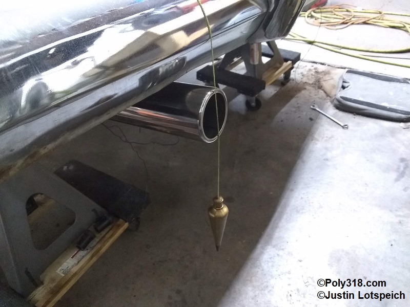
For placement, I dropped a plumb bob to mark the bumper apex as a benchmark and moved the sleeve forward and back while stepping back to view from all angles until I found an aesthetic sweet spot 1/2″ past the bumper apex (Figure 5o). This position will likely cause some soot to build up on the bumper over time due to idling that will easily wipe off, but moving it out far enough to stop the buildup looks ugly to me since the tips break up the curve of the bumper and protrude far enough to catch on one’s leg when entering the trunk. I marked the tailpipe at the front (toward the engine) of the sleeve, removed the sleeve, and made another mark 2.5″ farther toward rear. I cut the tailpipe at this mark so that when the tip is welded in place the mild-steel tailpipe extends only 2.5″ into the sleeve, is hidden,and keeps the mild-steel tubing away from the exhaust water and acids to prevent corrosion.
I stitch-welded the tip at the front (toward the engine) with three 1″ beads making sure to not weld the very bottom of the joint. My reasoning for welding in this way was because the joint is not structural, it does not need a seal, to limit the heat affected zone so as to not discolor the stainless steel blue/purple where it would be visible, and to leave the bottom open so exhaust water and acids can drain out the front (toward the engine) and not pool and corrode the mild-steel tailpipe.
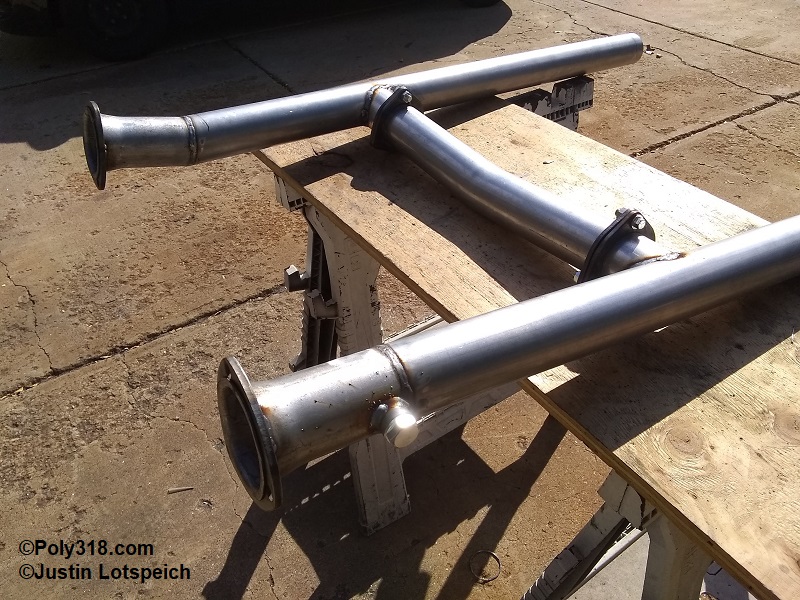
Fabricating the “H” Crossover:
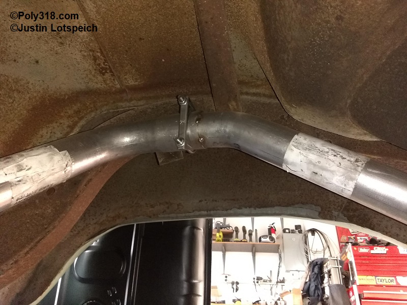
I had the two mid-length tubes from the JEGS kit (the top of Figure 5a above), and one of them had a shallow bend in it that forms a “V” that would work nicely under the transmission tail housing long enough to span between both exhaust head pipes. I was able to locate the crossover 14″ behind the start of the head pipe/header flange for enough clearance around the transmission and to allow enough room around the drop-out connectors. I marked each head pipe for that location pulling the measurements off chassis points that I knew would place the crossover square with the chassis rather than relying on the header flanges. I chose to build a bolt-in crossover so I can easily install and remove the transmission without having to drop the exhaust. I first cut two 3″ long pieces of straight 2.5″ diameter tubing from some drops and used the cutoff wheel and then sanding disc to notch a bird’s mouth into one end of each piece. Placing the bird’s mouth up against the head pipes under the car, I traced the outside of the bird’s mouth onto the head pipe with a permanent marker and noted a “left” and “right” onto the head pipes and short pieces. After removing the head pipes, I used a hole saw to cut out most of the area and a carbide bit in a pneumatic die grinder to bring the hole out to just before the permanent marker line and de-burred the inside of the tubes.
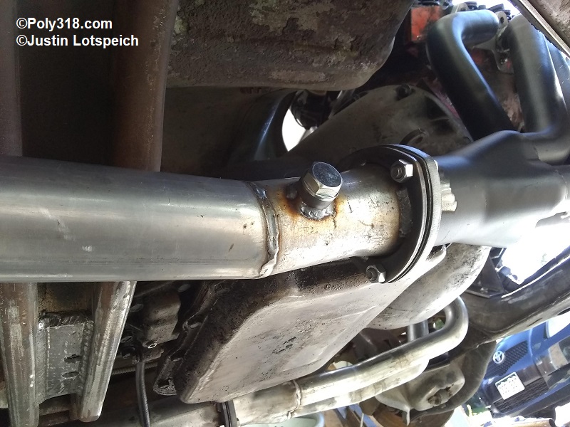
To assemble the components, I tack-welded the short pieces onto their respective head pipes, placed the 3-bolt flange onto the short tubes, and tack-welded the inside of the flange to the tube in an even orientation with the single bolt facing up. I slid the head pipes into the mufflers, secured them to the headers, and took the measurement from the inside of one head pipe to the inside of the other (not the flanges). I cut the crossover tube with the subtle “V” centered over the tail housing to this measurement minus 1/2″ to allow for temporary fitment. I placed the crossover up against the sides of the short flanges on the head pipes and rotated the head pipes until the short flanged tubes were at the same downward angle as the “V” crossover. I marked the side of the crossover with permanent marker at both of the flanges. I subtracted 1/8″ off each side of the marks to account for a 1/16″ gasket and 1/16″ so the crossover would rest 1/16″ inside the flanges not yet welded on. After cutting the crossover tube square, I bolted the gasket and second set of flanges to the head pipe flanges and slipped in the crossover pipe. I rotated the crossover tube so the “V” pointed down and placed three small tack welds to secure the crossover to its flanges. At this point, I marked the head-pipe reducers where I would drill the holes for the oxygen sensor bungs since I use an oxygen sensor to tune the dual carburetors. I removed the head pipe/crossover assembly, finished the welds, drilled the oxygen sensor holes, and welded on those bungs (Figures 5p – 5q). I installed the assembly, checked that everything was aligned and bolted down, and tack-welded the head pipes to the muffler inlets.
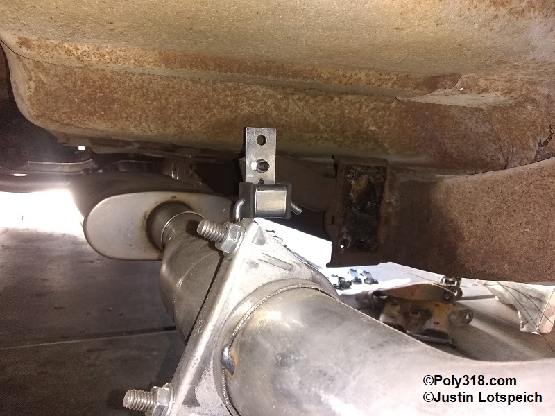
Hanger Placement:
With the entire exhaust system now tack-welded, I focused on the hangers. There is no standard for the quantity of hangers, but the system should be very well supported to where it does not move around excessively and that unnecessary stress is not placed on components. If anyone is curious, the factory 1955 – 1956 Dodge/Plymouth design used two hangers–one behind the mufflers and the other at the tailpipes. The hangers I like using (Figure 3b above) have a straight 3/8″ hardened stainless steel rod that hangs down from the rubber damper mount. For the mid-system hangers that support closest to the mufflers, I used the leaf spring front mounting brackets as anchors. I bolted the hanger mount to the factory bracket on the right side and built a similar bracket for the left side (Figures 5r – 5s). I installed the hanger rod into the damper mount and marked it with a permanent marker at the center of the exhaust tube, placed the rod in a vice, heated the marked area with a torch, and used a piece of scrap pipe slipped over the hanger rod to bend a 90° turn. I cut off the rod leaving a 3″ leg. I installed the rod into the hanger and tack-welded the leg onto the tube similar to Figure 5r. For the tailpipe hanger, I was coincidentally able to use existing holes in the the back crossmember for the hanger mounts and bent, cut, and tack-welded the hanger rods to the tailpipe. With the temporary tie-wires removed allowing the system to hang from the headers, the middle hanger, and the rear hanger, I shook the entire length of the system and found it was held solid in place with no need for a third hanger before the mufflers.