Poly 318 Cylinder Head Disassembly, Cleaning, and Inspection
(applicable to 277, 301, 303, 313, 318, and 326)
Introduction
As part of my larger engine-building series (located on the top menu), I split the engine and cylinder head disassembly into separate articles. The cylinder head and rocker arm shaft disassembly procedure depends in part on your plans for the heads. If planning on reusing the valves by lapping them in without having any machine work performed (not recommended due to the unhardened exhaust seats), it is important to match them to the seats they came from. If reusing the valve springs (not recommended due to fatigue), it is important to match each valve, spring, retainer, and spring shim (if applicable) to reinstall them to the corresponding seat to maintain the proper height. Using an overturned cardboard box with numbered holes with the valve punched through it is an easy organization method. If a full rebuild and valve job will be performed, all parts can go into the same box unmarked since you or the machinist will set up the new springs and seat height.
Disassembly:
- Remove the spark plugs. Caution: Forcing a seized plug can strip the female threads requiring a thread insert. If the plug does not loosen easily, remove any carbon/corrosion buildup from the combustion chamber side. Apply penetrating oil to both sides and work the plug counterclockwise 1/4-turn, back clockwise, then counterclockwise 1/2 turn until it is removed to clear the threads of debris. Applying heat to the plug base with a propane or oxy-acetylene torch and wrapping on the flat end of the plug threads with a drift from the chamber side can assist, but do not damage the threads.
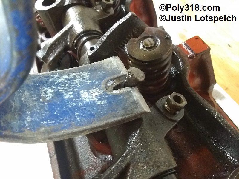
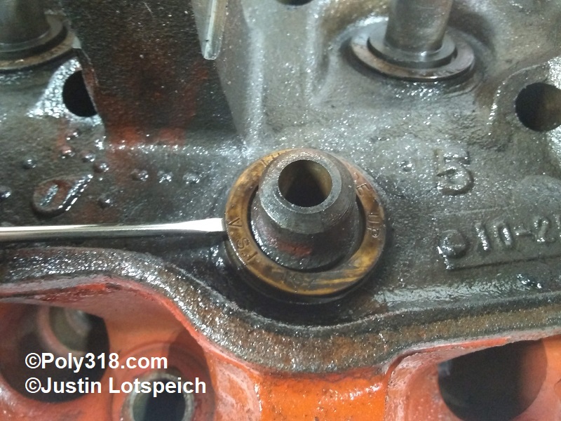
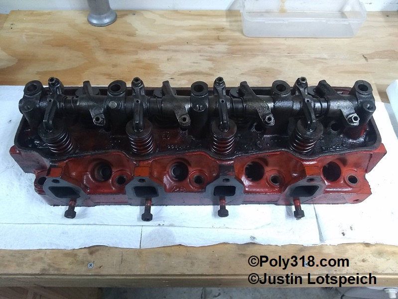
- Locate the rocker shaft locking pin. Using a flatbar, pull the pin up and remove it (Figure 1). Do not pry off the rocker shaft/arms. Using heat on the cast tower from a propane or oxy-acetylene torch and penetrating oil may be required for engines with excessive varnish.
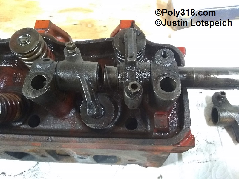
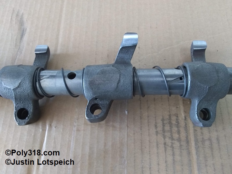
- Slide the rocker shaft out catching the rocker arms and springs and keeping them in order for inspection (Figure 2). Once removed, slide the rocker arms and springs back onto the shaft in order, note with a marker or tape which head the rocker assembly came from, and put aside until inspection and cleaning.
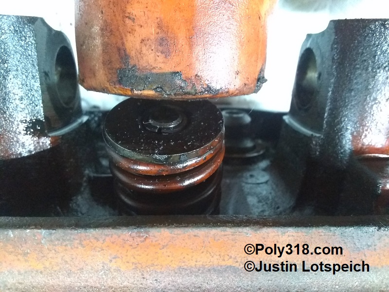
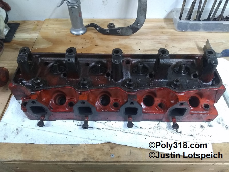
- With the head flat on the workbench, wrap sharply down on each spring retainer edge once with a rubber mallet to break any tension between the keepers and retainer (Figure 3)
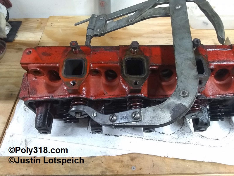
- Flip the head onto its side. Compress a valve spring using a compressor, remove the keepers, release the tool pressure slowly, and remove the retainer, spring, and stem seal (Figure 4). Proceed with removing the remaining three valves before rotating/flipping the head and removing the other bank of valves. Note: If not replacing the valve guides and the valve does not pull out smoothly, stop and file any burrs from the locking grooves and tip edge so the valve stem does not gouge the guide when removing.
- Use a screwdriver to remove the valve spring shims if installed (Figure 5). These shims are numbered for their thickness and are used to adjust spring height and must be matched with their valve/spring/retainer assembly if reusing the valves and springs without machine work. If a valve job will be performed and/or new springs installed, the installed height and seat pressure should be checked/adjusted to the new components.
- Using vice grips, remove the exhaust manifold studs. Expect to replace them since they will be damaged during removal, but it is wise to remove them to ensure the new ones are properly sealed since the lower row goes through to coolant. They will likely be tight and may require torch heat and penetrating oil to break loose.
Cleaning and Preparing Heads, Rocker Arm Shafts, and Parts
- The cylinder heads should be thoroughly cleaned in either a hot tank or by scrubbing and using a pressure washer to remove all grime/dirt. The water ports and jackets should be cleaned with a pick if necessary and blown out well with water. If not setup and capable of doing one’s own valve and guide work, consult a qualified machinist; for lapping in existing valves, consult a reputable repair manual. I recommend installing hardened exhaust seats to eliminate the need for expensive and burdensome lead additives in the gasoline, especially on engines that will see sustained higher rpms. For performance builds, the factory valves are small and will limit power, so 1.94″/1.60″, 2.02″/1.60″, or 2.05″/1.60″ configurations should be considered.
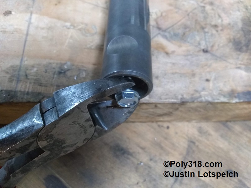
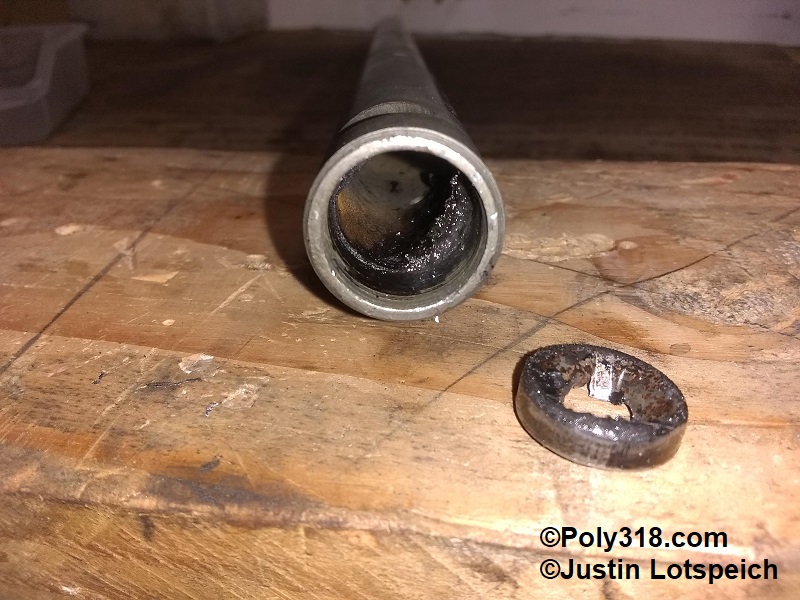
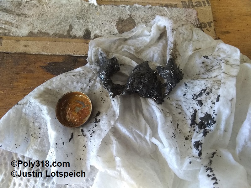
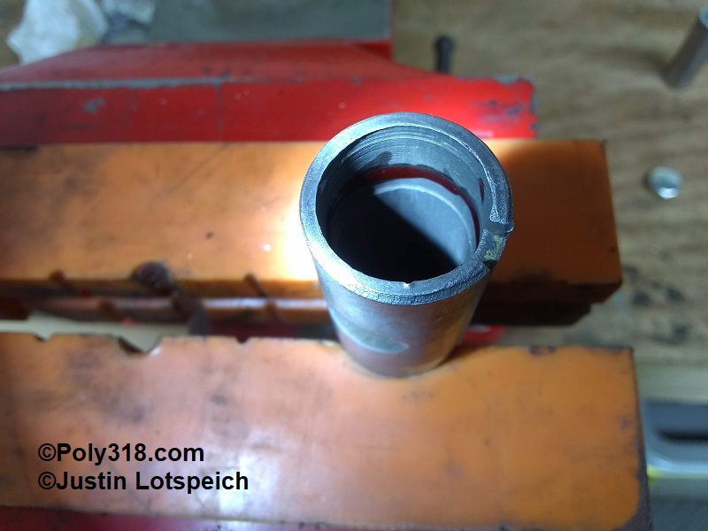
- Despite what one might read online, the rocker arm shaft expansion plugs should be removed in order to properly clean the inside of the shafts. Many people assume that hot tanks or ultrasonic cleaners will remove all grime/dirt from inside the shaft, but Figures 7 and 8 show the grime that came out of a rocker arm shaft that I had already hot tanked and run for sixty minutes in a heated ultrasonic bath of strong cleaner. I am not comfortable having this grime/dirt buildup in a rebuilt engine’s oiling system upstream of the rocker arms where it can flow onto other components before reaching the oil pan. To remove the plugs, drill in a self-tapping sheet-metal screw and pry the plug out use wire cutters (Figure 6). The plugs are very thin, so the screw will likely strip out where a screwdriver can be inserted to finish prying out the plug. After one plug is removed, use a long rod to drive out the other plug.
- With a strong solvent or mixture of degreasing soap and water, use a long rifle brush larger than the inside diameter to thoroughly clean out the shafts. A toothpick can be used to clean out the rocker-arm oiling holes as the sludge is pushed into them by the rifle brush. Rinse everything thoroughly with water and blow dry with air before flash rust develops.
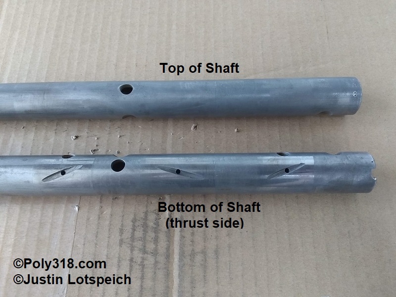
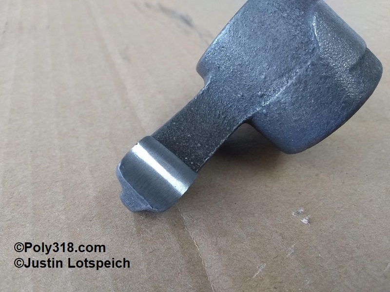
- Inspect the shafts closely for damage and excessive wear in the rocker arm areas. In general, the bottom of the shaft will show polished signs of wear since the pushrods and valve springs force the rocker arms up against the bottom thrust side of the shaft (Figure 9). Use a pick to feel for any wear ridge from the polished area to where the shaft rides in the tower bore. Use an outside micrometer to measure the shaft from the bottom to top, side to side, and where the shaft rides in the tower. The diameter of the shaft inside the tower serves as the benchmark since there is no wear here. Checking the shaft at the rocker arm from top/bottom and comparing to side/side will show if the shaft is worn out of round. If the shaft is still round and there is not a wear ridge, it is reusable. If it is worn excessively and/or out of round, a good used/NOS replacement should be secured or the shafts and rocker arms should be sent to Rocker Arms Unlimited (California) for reconditioning. Slight nicks/blemishes can be lightly knocked down with 800-grit crocus cloth buffing around the shaft so as to not create flat spots.
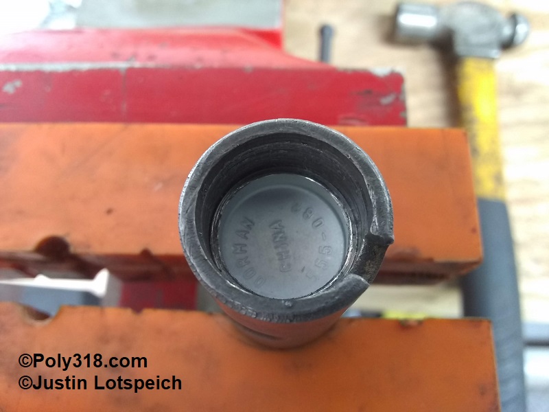
- If the shafts check out as usable, obtain four expansion deep-cup plugs. Some 1956 – 1961 shafts take a 5/8 plug (Pioneer EPC52) and others a 45/64″ (Dorman 555-082) or 11/16″ (Melling PC144). Note: The LA and B/RB shaft plugs are smaller than the poly 318 rocker arm shaft expansion plugs, and the A-block plugs are not reproduced. I have researched and personally tried five different plugs, and the above three options are the closet fits. With the shaft secured in a soft-jawed vice being careful not to distort the shaft, use a Q-tip to spread a thin bead of red Loctite around the inside wall where the plug will ride against the machined ridge (Figure 10). Drive in the new plug evenly and carefully using a bearing driver or socket that covers the outside lip (Figure 11); don’t drive against the inside of the plug since it can distort and possibly tear it. Drive the plug down until it seats evenly against the ridge. The plug will be firm to start but will compress nicely for a firm final fit without distorting the shaft. Note that typically the ridge on one end of the shaft is machined deeper than the other end. When finished, use compressed air to blow off any shaving from the ends and to blow into the shaft with the large oiling holes facing down to remove any possible shavings.
- Turning my attention to the rocker arms, I remove the adjuster screws (if applicable) and will replace them with longer 3/8″-14 screws with jam nuts. I clean the arms in an ultrasonic bath of Pine-Sol, rinse in water, and immediately blow dry to stop flash rust. Inspect the inside bore visually and with a pick for any damage and wear. Most wear will be on the bottom of the bore. Using an inside micrometer or a telescoping bore gauge and outside micrometer, measure the bore from top to bottom and side to side, comparing the two numbers to check for wear out of round. Subtract the smallest rocker arm shaft diameter measured before at the rocker arm for the total clearance. While standard engine physics calls for .001″ per one inch of shaft diameter, the A-block assemblies I’ve measured including low-mile assemblies come in closer to .003″ clearance. Thermal expansion does not factor into this clearance since the forged shaft and the ductile cast iron arms expand at about the same rate. If the rocker arm bores are not out of round and the clearance is under .0035″, I would reuse them for a stock or medium-performance build. If the arm bores are out of round, the clearance is over .0035″, or the engine will see strong spring pressures and aggressive cam profiles, I’d send the assemblies to Rocker Arms Unlimited for reconditioning.
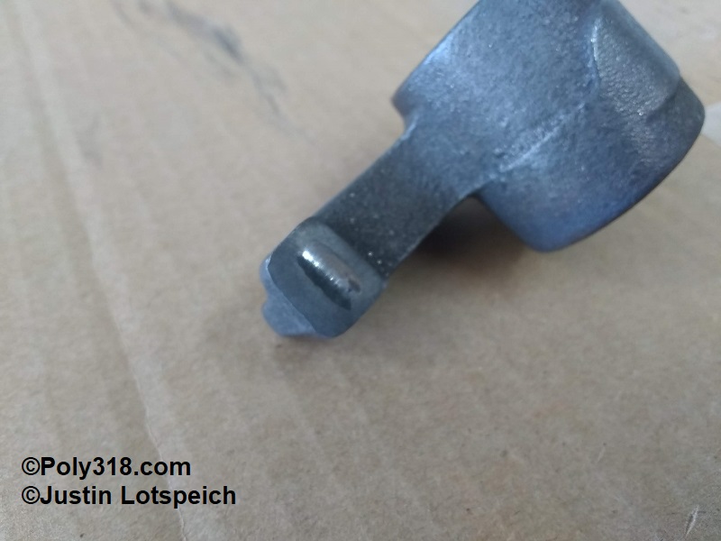
- If the rocker arm bores and clearance check out as usable, inspect the rocker arm tips for excessive wear including flat spots and grooves from the valve stems (Figure 12). I sand the tips on a piece of 320-grit emery cloth laid on a flat machinist’s straight-edge to easily see the wear patter. If the wear is not excessive and can be easily sanded out, I use a rocking motion on he emery cloth to evenly sand the tip keeping light pressure with one finger on the tip so it lays flat on the sandpaper. I finish the tips using 800-grit paper wetted with WD40 (Figure 13). Any severely gouged or worn arms should be either replaced with a good used/NOS unit or sent to Rocker Arms Unlimited for reconditioning.
- Note: Some older quality aftermarket and factory NOS arms are still available on secondhand online marketplaces, but there are also new inferior Chinese-made arms available. Be careful to ensure the replacement arms are either factory or US-made aftermarket, especially with camshafts and valve springs more aggressive than stock.
- Lastly, inspect the shaft springs to ensure they still have good flexibility, tension, and are not broken. Cylinder head disassembly, cleaning, and prep are complete (Figure 14).
Figures