1960’s Dodge, Plymouth, Chrysler
Thompson (TRW) & Federal
Power Steering Pump
Identification, Dynamics, & Rebuild
Video of the Following Process Demonstrated Below
-Click for my YouTube video of this article-
Power Steering Pump Manufacturer Identification
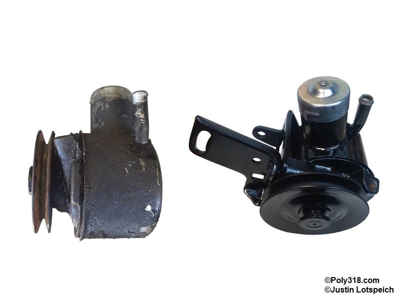
1960’s Dodge, Plymouth, and Chrysler used both Thompson (TRW) and Federal pumps (along with Saginaw not covered here), often in parts catalogs called a “Chrysler” pump. The following details identify the pump manufacturer from the exterior:
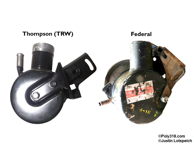
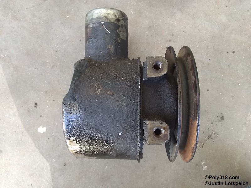
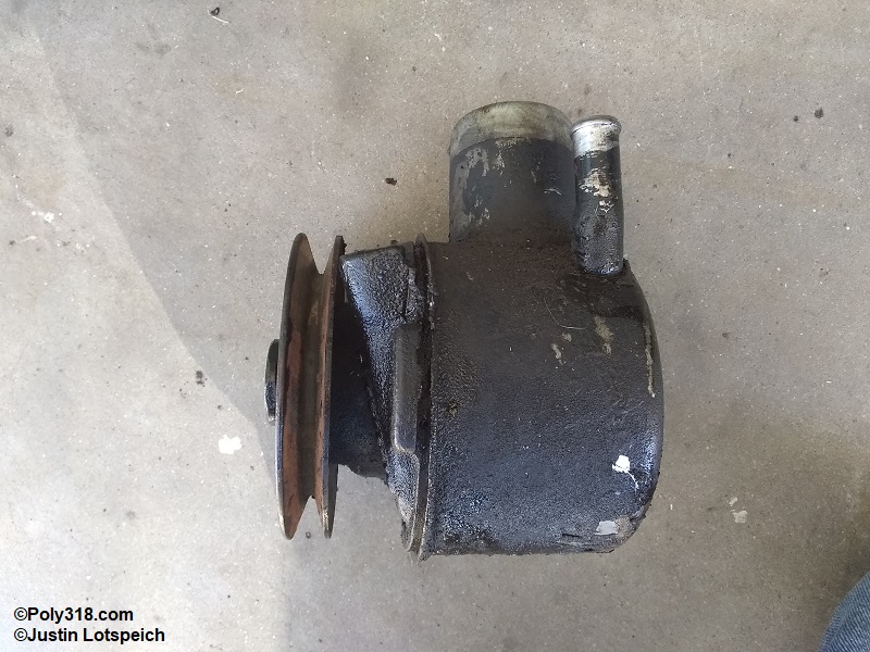
The Thompson (TRW) rotor shaft end is either plain, hex, or slotted. The back of the reservoir has a long indentation with either one or two bolts (Figure 1).
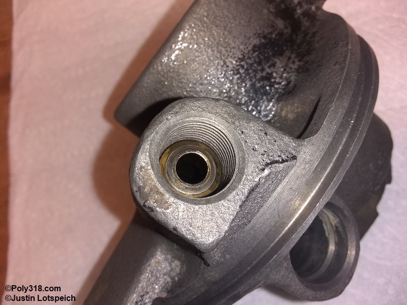
The Federal rotor shaft end is threaded. The back of the reservoir has a short indentation with one bolt (Figure 1).
Power Steering Pump Model Identification
Thompson (TRW) and Federal built two different models 0.96 and 1.2 named after their cubic inch displacement of the chamber, sometimes referred to as a “small” and “large” pump. The difference is mainly in the diameter of the rotor. Both pumps flow approximately two gallons per minute according to factory literature. This article is applicable to both manufacturers and models.
The following elements identify the pump model from the exterior:
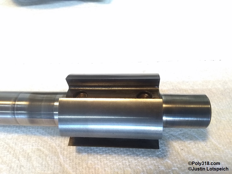
Model 0.96: The rotor shaft that the pulley attaches to is 0.675″ diameter
Model 1.2: The rotor shaft that the pulley attaches to is 0.80″ diameter
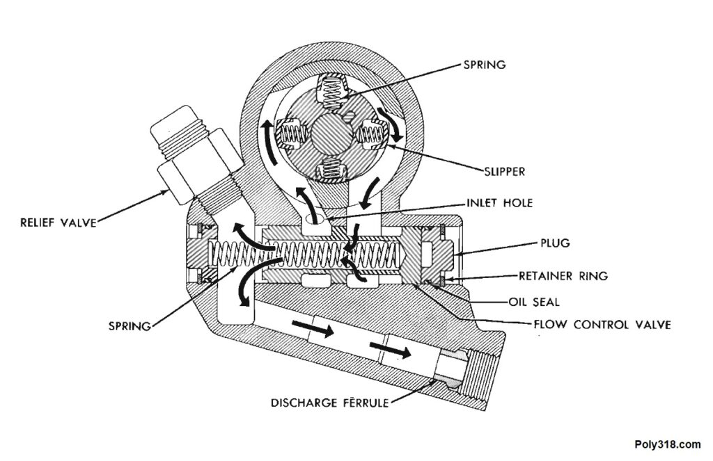
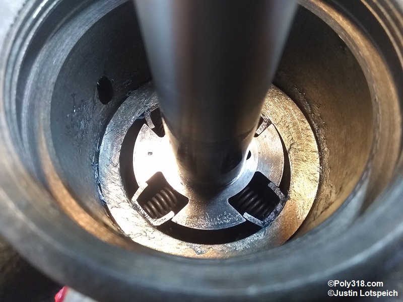
Power Steering Pump Dynamics (Figure 2)
The 0.96 and 1.2 pumps utilize a rotor that rides inside an eccentric cam insert. Four spring-loaded metal slippers create a seal on the insert walls. The slippers push fluid from the inlet side, through the flow-control valve, and into the discharge port where it flows to the steering gear. The control valve increases flow at lower RPM for better steering and decreases flow at higher RPM to keep the fluid from overheating. The relief valve sets the maximum pressure allowed before the fluid dumps back into the reservoir.
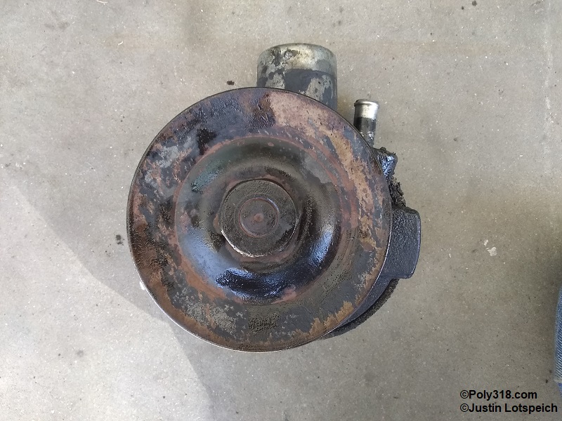
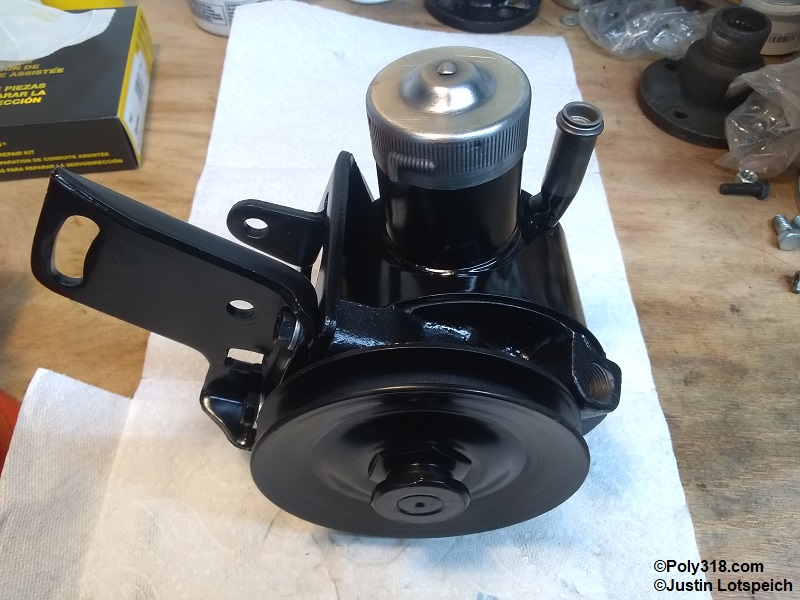
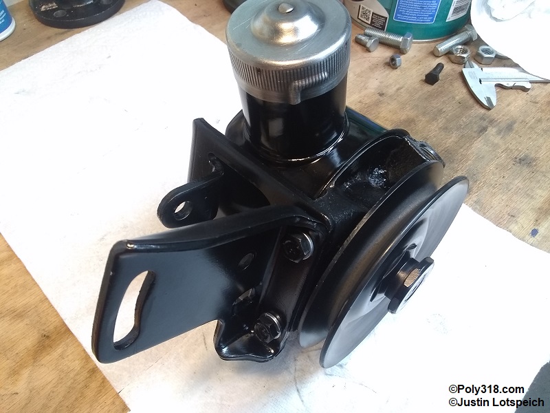
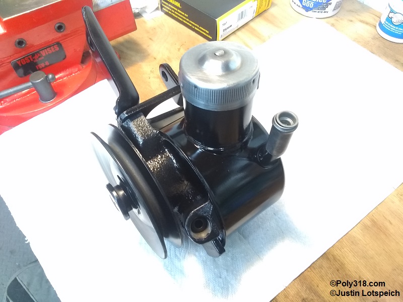
Power Steering Pump before Rebuild
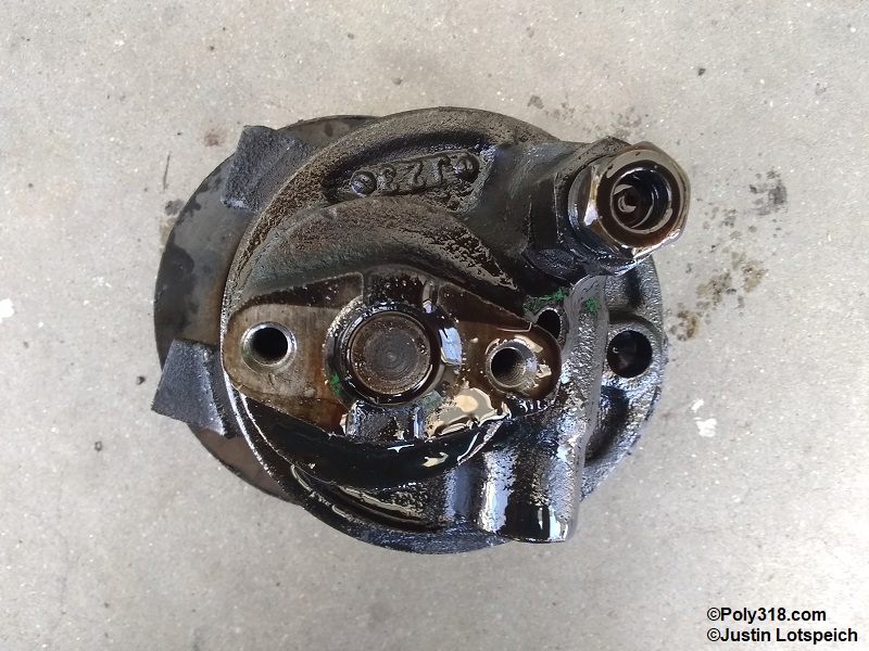
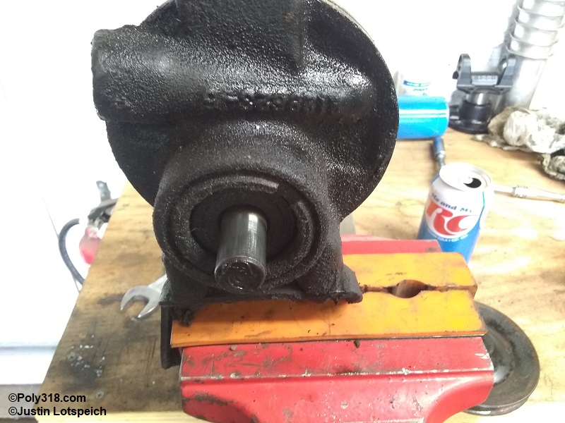
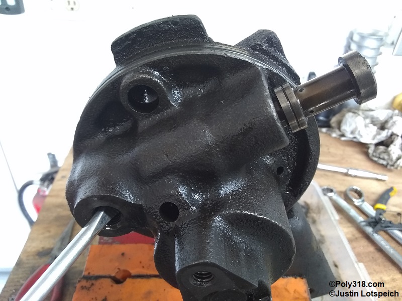
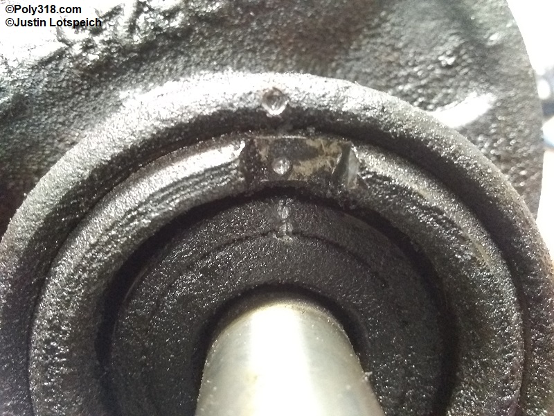
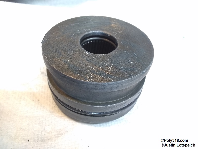
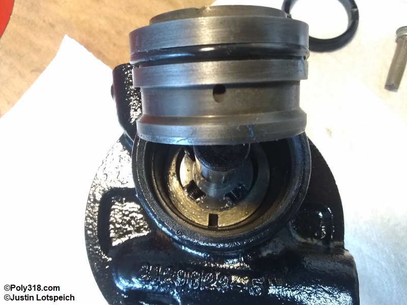
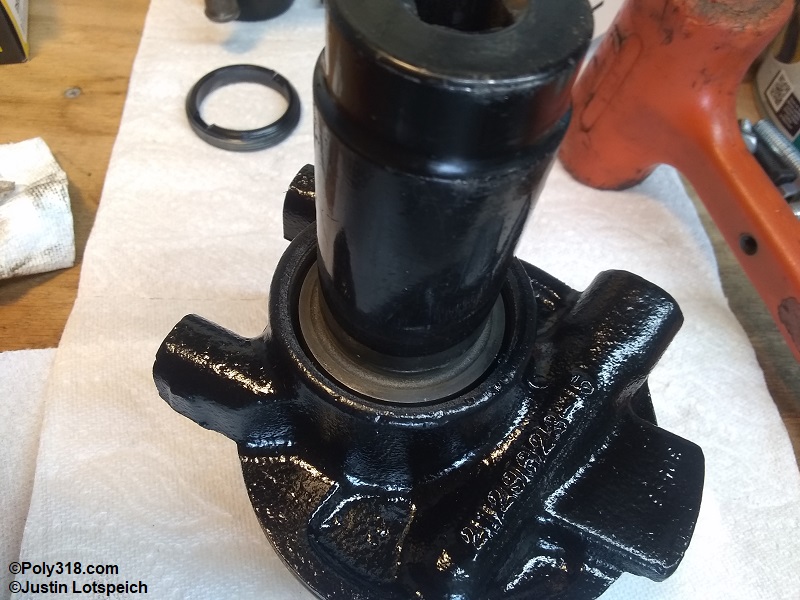
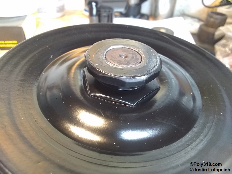
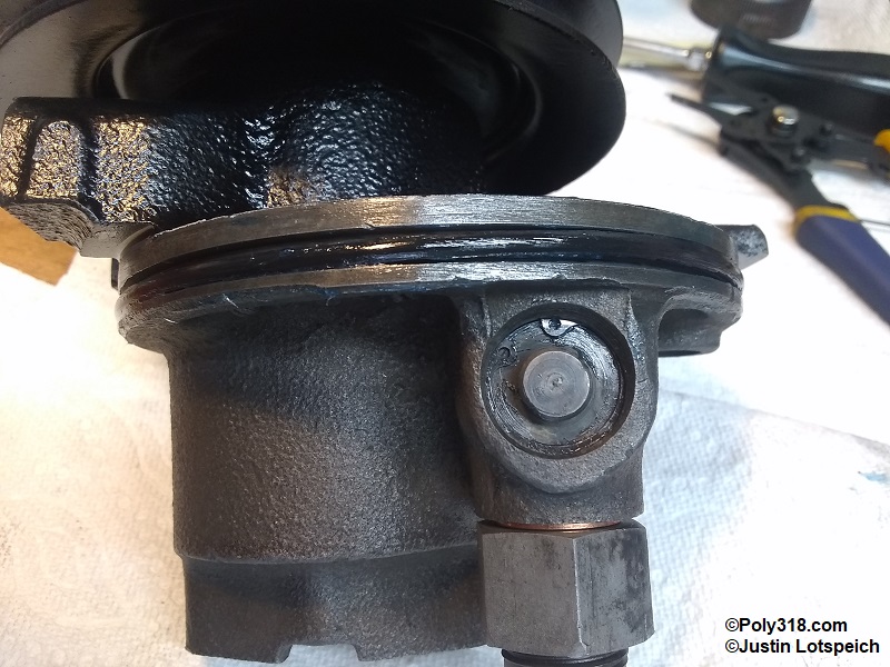
The pump I rebuild in this video is a Thompson (TRW) model 0.96 from a 1964 Dodge Polara. I never witnessed the pump running, so its condition was unknown aside from a preliminary inspection. The pulley/rotor shaft spun freely, and there was no slop when moving the pulley side to side (Figure 3a – 3c).
Power Steering Pump Pulley Removal
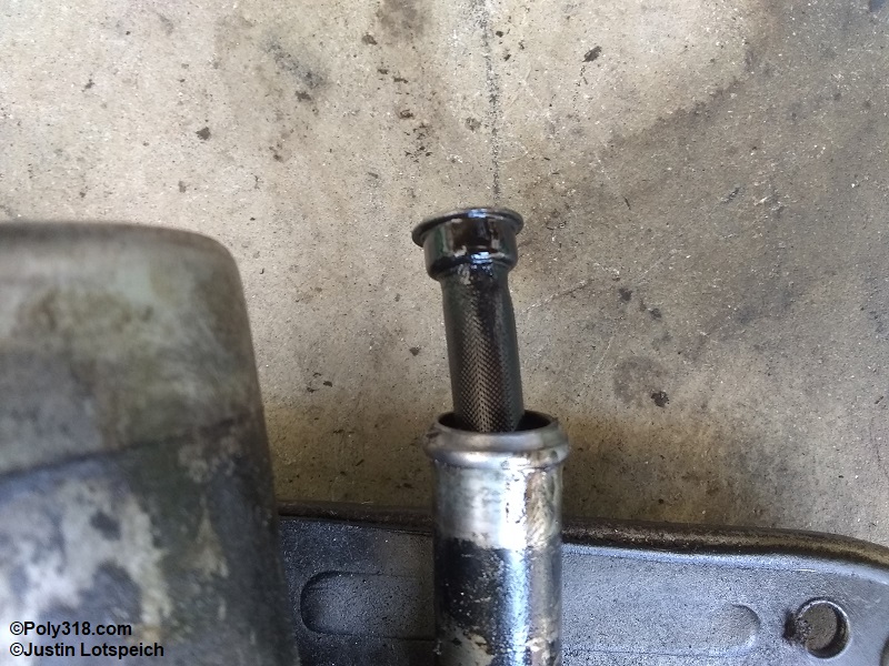
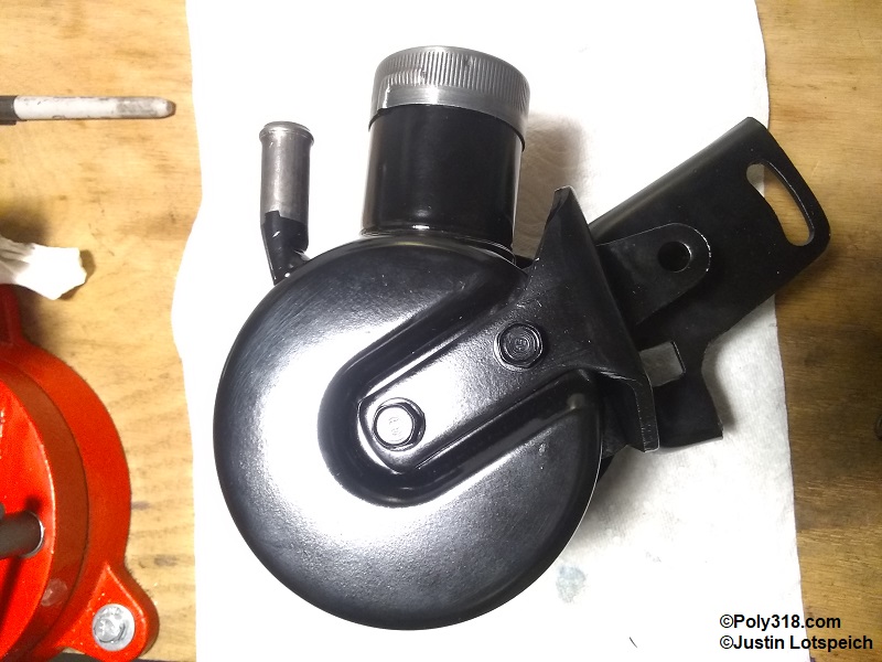
To start the disassembly, remove the side mount bolts from the pump and the bolt(s) holding the bracket to the back of the reservoir/pump. If equipped, remove and set aside the return filter, although these are often missing (Figure 4a).
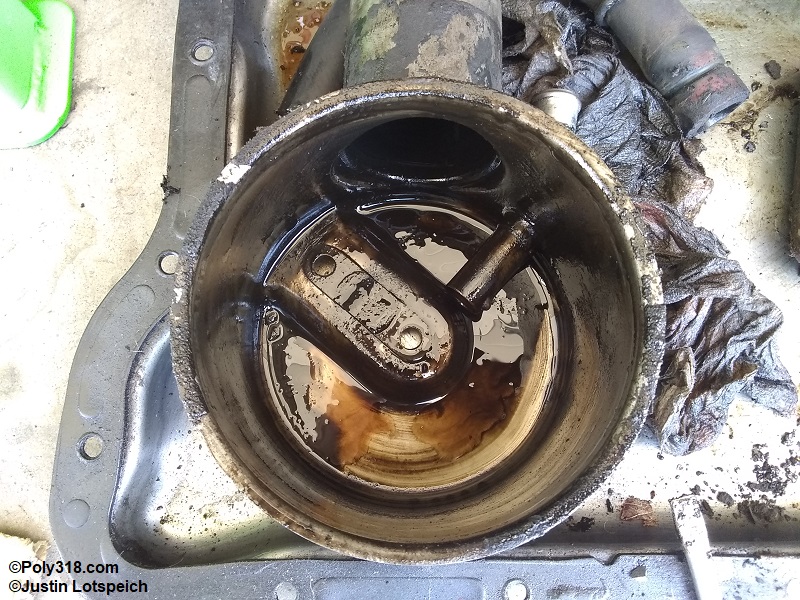
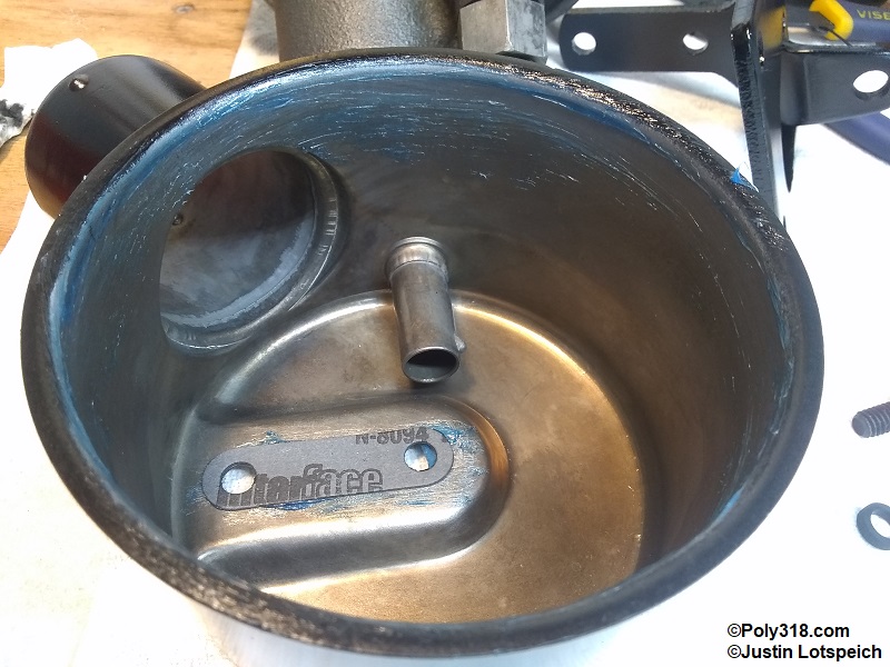
Using a large screwdriver or flat bar between the pump and reservoir at the two side bracket mounting ears and on the opposite ear, gently and evenly pry the reservoir away from the pump. Do not pull on the filler neck, use a mallet, or bend the reservoir. It should come off easily prying back and forth at the proper pry points. Remove the reservoir and set aside (Figure 4b). Inspect the inside of the reservoir for metal shavings and other debris that may suggest excessive wear or damage, and set aside the rear gasket (Figure 4c).
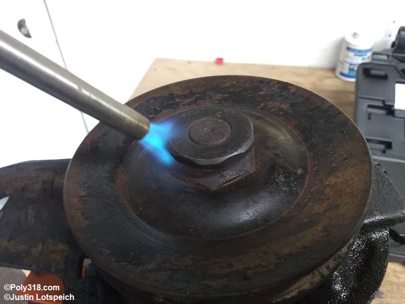
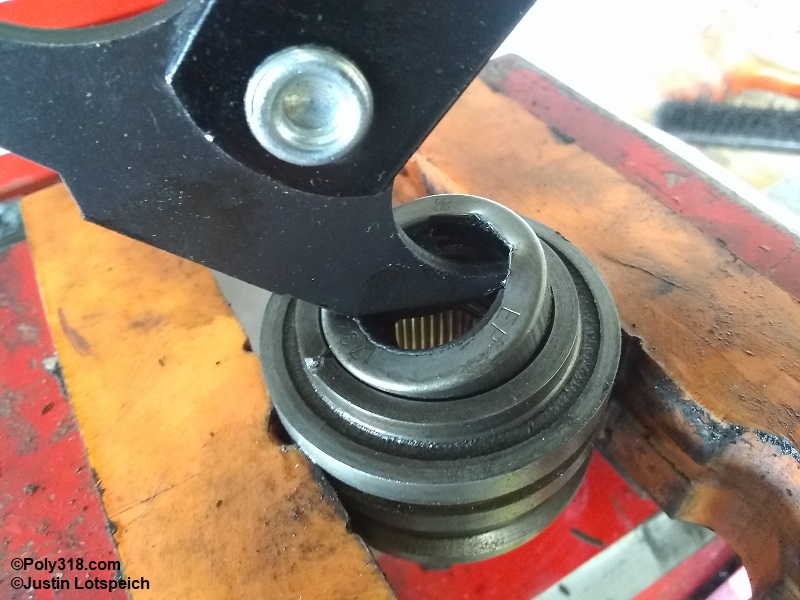
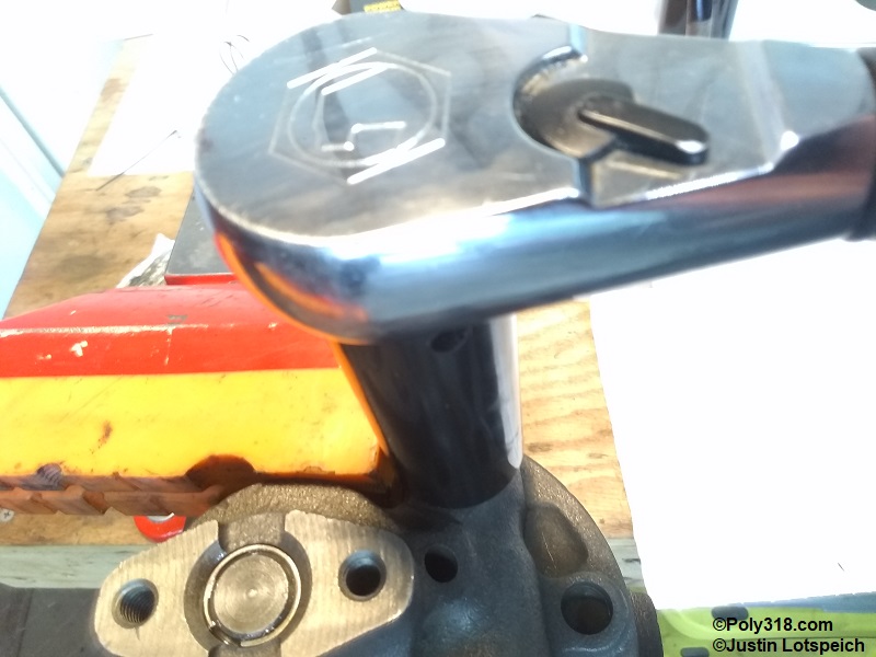
Temporarily reinstall the side mounting bracket to secure the pump in a bench vise. Using a torch, heat the pulley hub sides to approx. 600F trying to keep the direct flame off of the rotor shaft (Figure 4d).
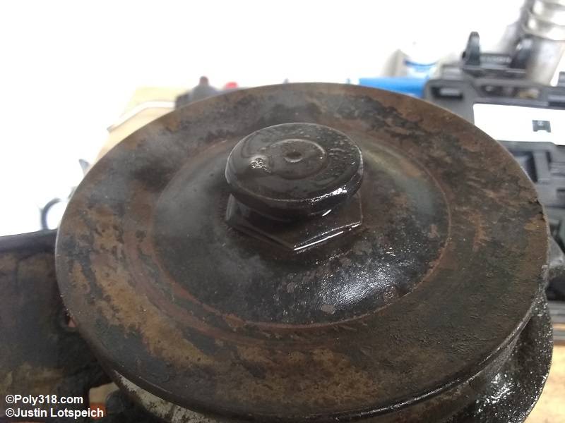
Immediately apply a quality penetrating oil like Deep Creep to the hub. The heat expands the hub to break the bond, and the penetrating oil will seep into the gap. The air bubbles pictured demonstrate the oil soaking in (Figure 4e). Warning: The penetrating oil is flammable and will create smoke and possible fire.
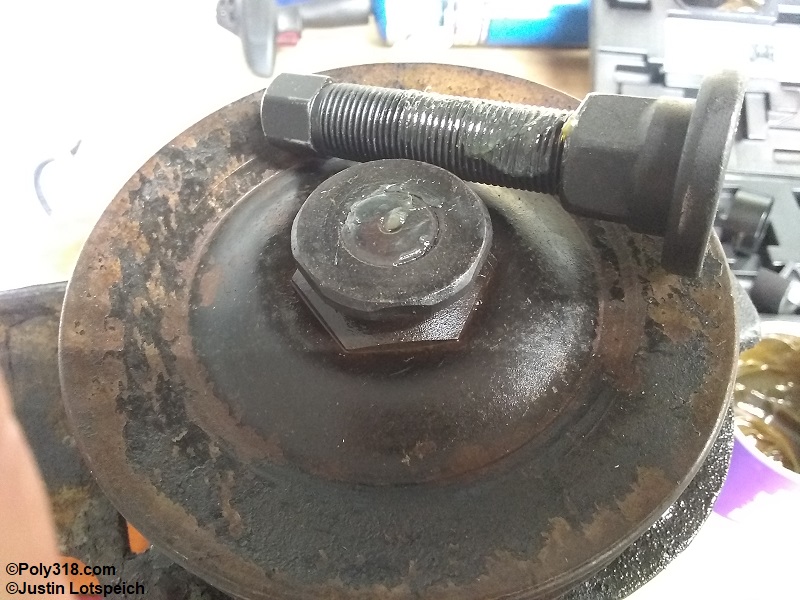
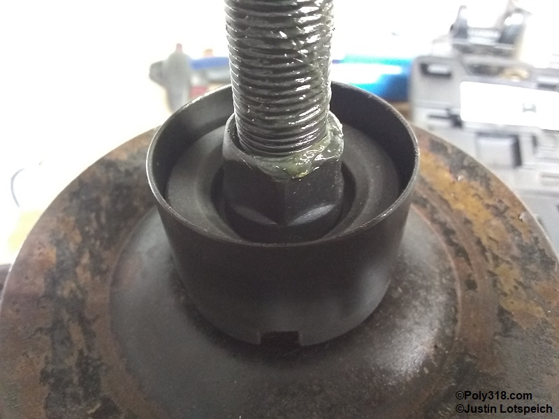
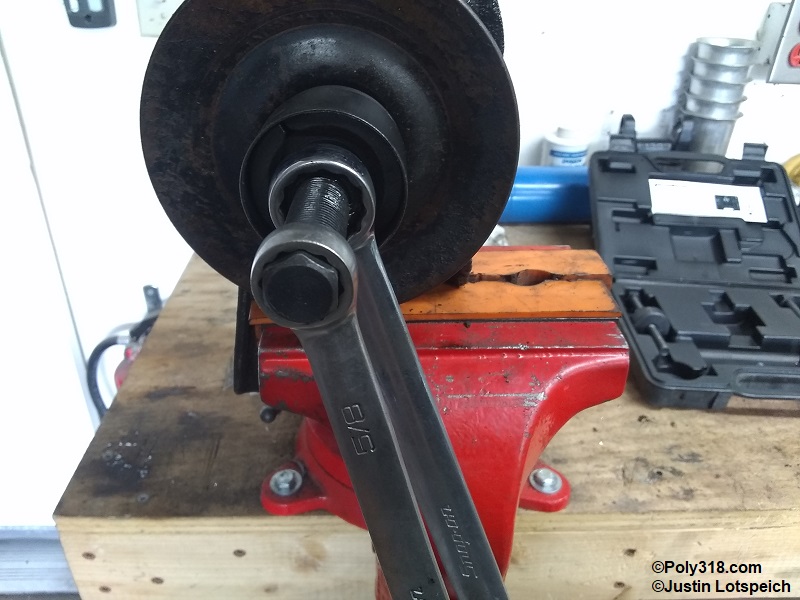
Liberally grease the puller screw and the tip of the shaft (Figure 4f). Slide one half of the puller body into the side of the pulley hub, slide in the screw foot, slide in the second half of the body, and slide the outer sleeve over the body to secure the two halves in place (Figure 4g). Holding the puller foot with one wrench, tighten the screw clockwise to pull the pulley off the rotor shaft (Figure 4h). I position the wrench holding the foot up against the vice handle in a way that pins it so I can focus both arms on turning the screw. The pulley should make an initial pop noise as the bond breaks and then should smoothly pull off. Backing up the screw wrench with another wrench or cheater bar for leverage may be necessary. I don’t use an impact gun because the slow tension of the wrench does a better job breaking the pulley free while not straining the threads. Remove the pulley from the shaft and the puller from the pulley. Inspect the inside of the pulley hub and the rotor shaft for any damage (Figure 4i). Light damage such as burrs can be sanded smooth with 1,000+ grit crocus cloth. This pulley and shaft had no damage.
Power Steering Pump Housing Disassembly
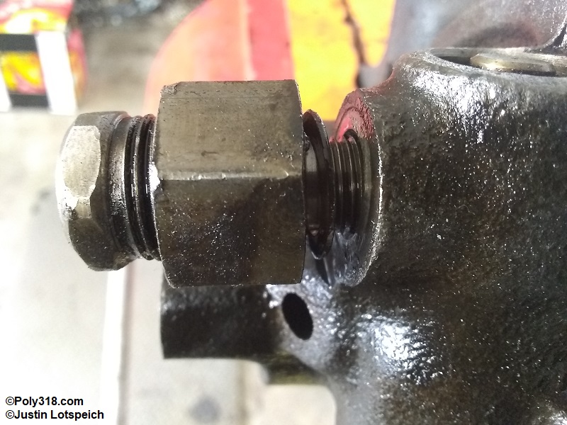
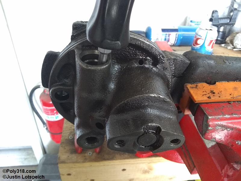
Using a deep socket or wrench on the larger pressure-relief valve body closest to the pump housing, remove the valve counterclockwise (Figure 5a). Set aside the valve and copper washer. Warning: DO NOT move the smaller nut in the end of the valve body. That nut loads the inner spring to set the valve psi at the factory, and the valve body is peened to lock the nut. With enough force, the nut will move, which throws off the valve’s psi setting.
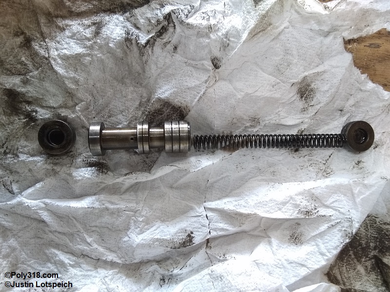
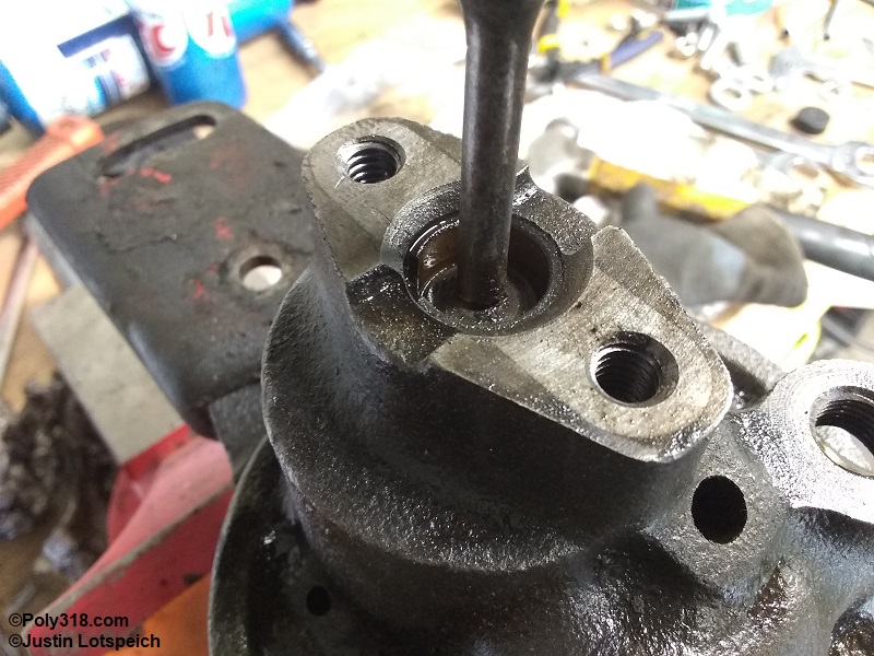
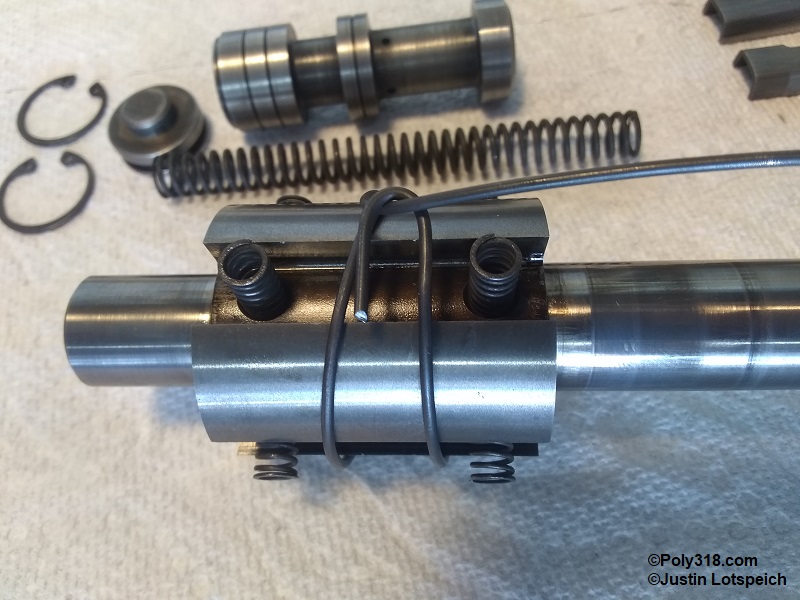
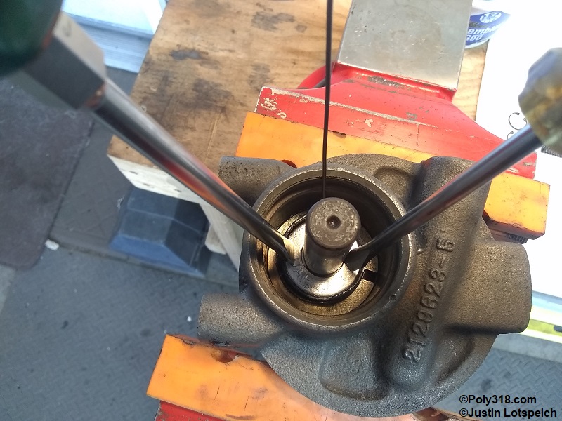
Remove the circlip at each end of the flow-control valve and set them aside (Figure 5b). Using a pair of needle-nose pliers, pull out the plug adjacent to the output port. Attempt to remove the other plug, but leave it if it doesn’t easily pull out. Insert a flat screwdriver through the relief-valve port into the control-valve spring, and gently pry out the control valve piston (Figure 5c). Alternatively, use a strong magnet to pull out the valve. Set aside the piston and spring being very careful not to damage the piston. If the plug on the relief-valve side of the pump would not pull out easily, insert a drift or screwdriver, and push/knock out the plug catching it (Figure 5d). The flow-control valve is made up of the two plugs (both identical), the spring, and the piston (Figure 5e).
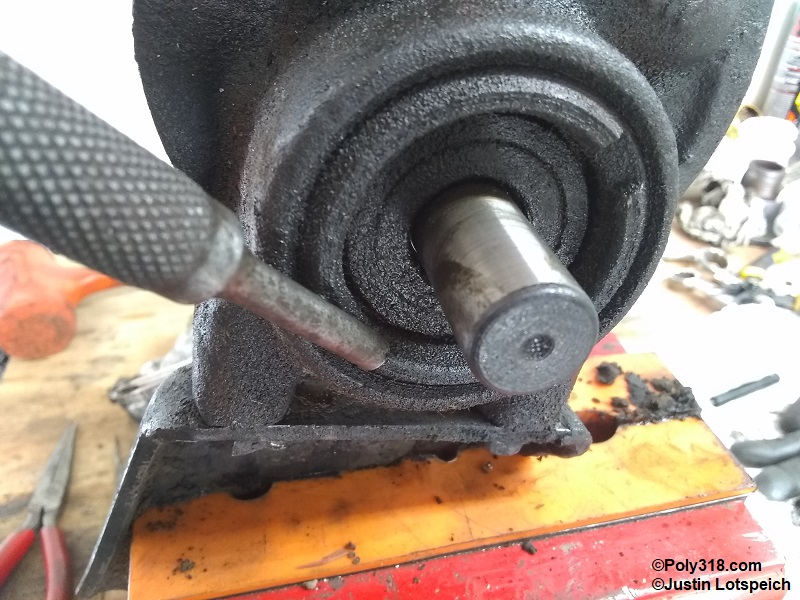
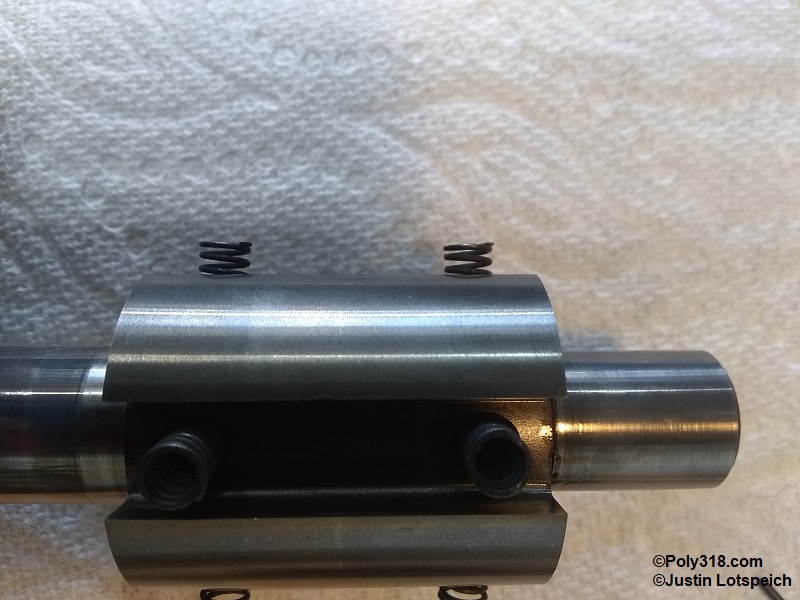
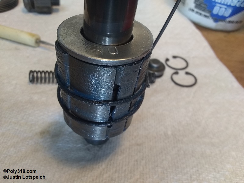
Before removing the spanner nut that secures the rotor bearing insert, use a center punch in a straight line to mark the insert, spanner nut, and pump housing (Figure 5f). Warning: This step is critical to properly align oiling ports and to torque the spanner nut to the factory specification. Use a drift and hammer to unscrew the spanner nut counterclockwise and remove (Figure 5g).
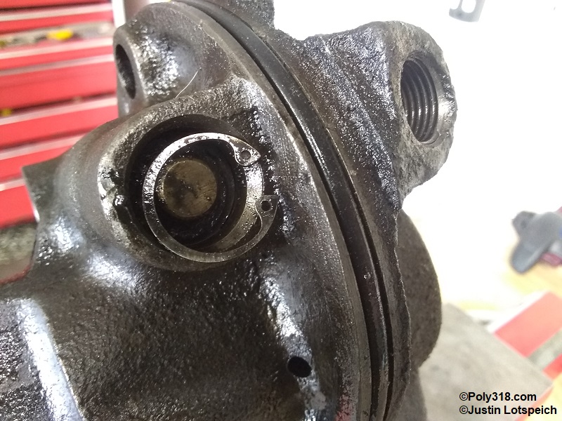
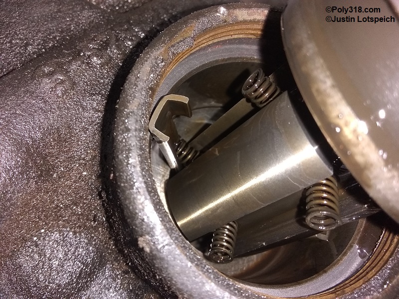
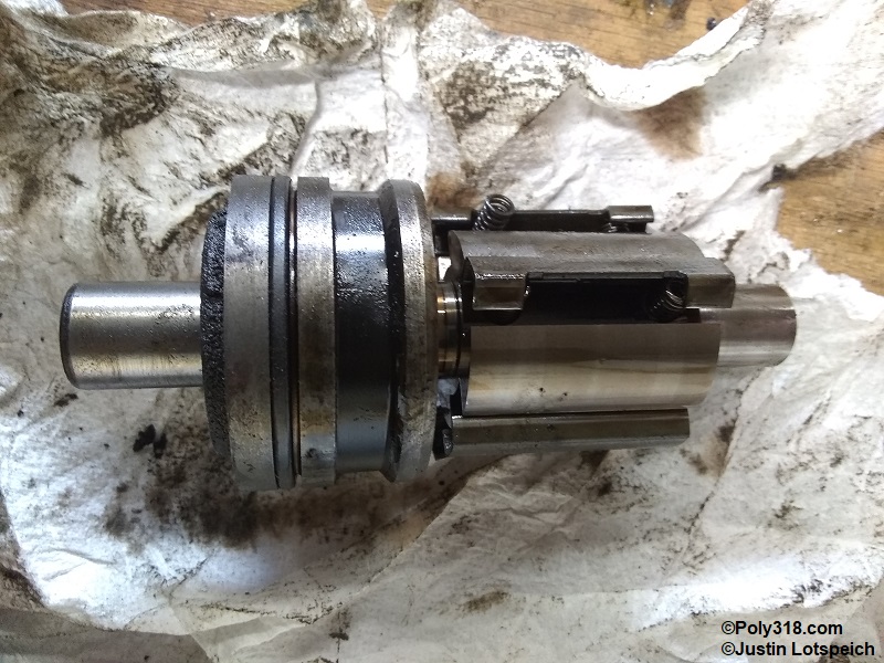
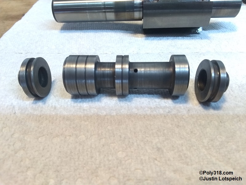
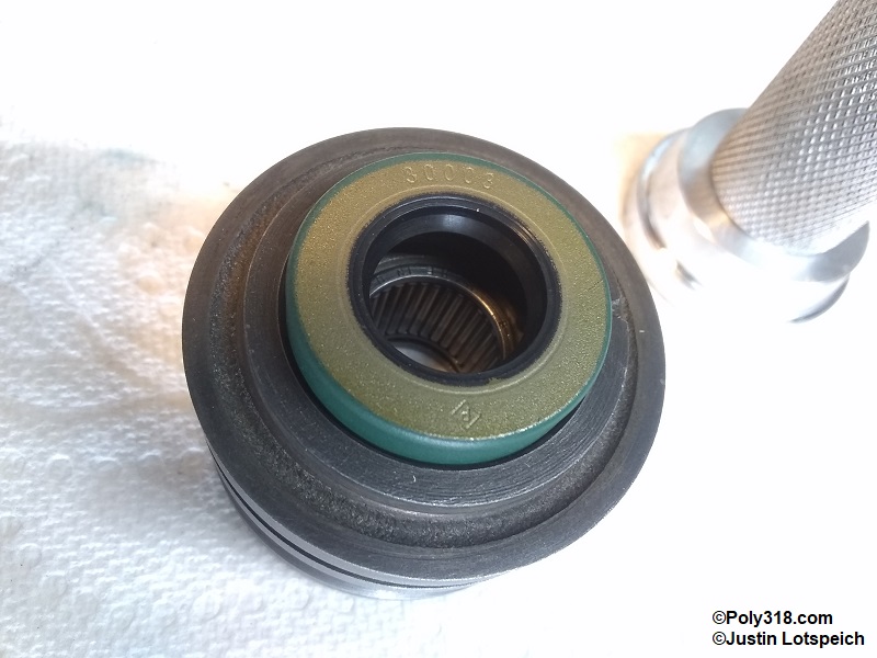
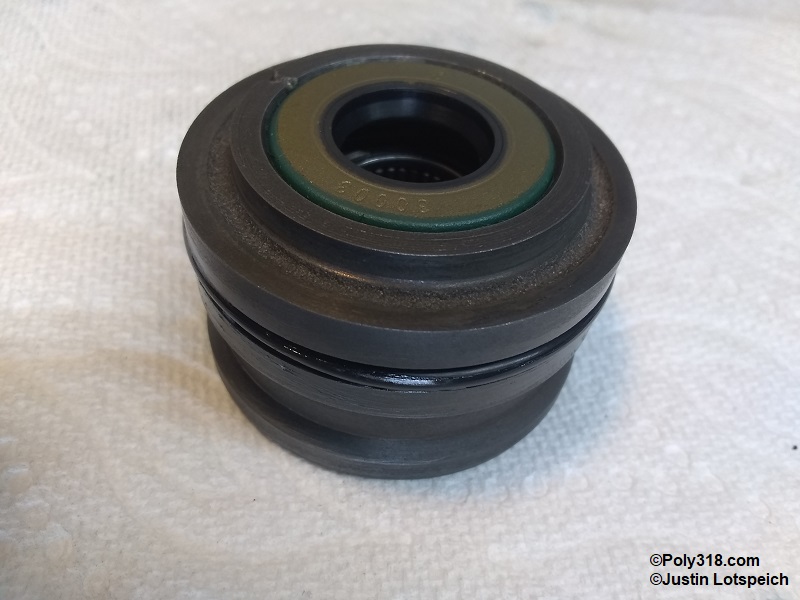
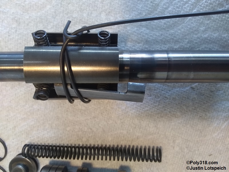
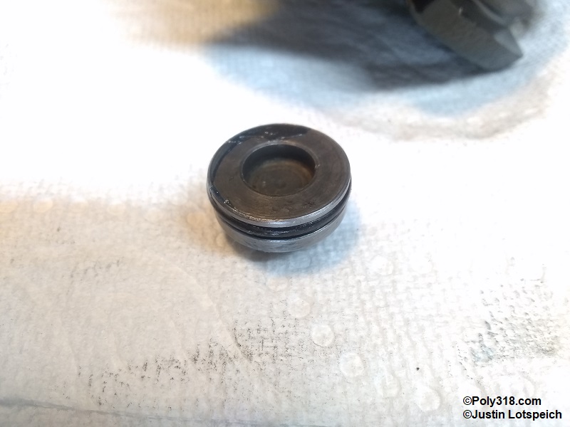
Position the pump housing with the back end of the rotor shaft pointing up and where the rotor bearing insert is clear to drop out. Use a drift to gently hammer out the shaft just until the bearing insert can be removed (Figure 5h). The insert is held in with an o-ring seal and should come out easily. Warning: Don’t damage the rear bushing/bearing with the drift, and support the bearing insert and the rotor so they doesn’t drop to the floor. With the pump housing positioned with the pulley end facing up, very carefully and slowly lift the rotor and shaft out of the cam insert (Figure 5i). Be prepared for the four slippers to pop out, and focus on not damaging them. Once the rotor is removed, twist and pull out the eight slipper springs. Looking at Figure 5j, the bearing insert houses the bearing, secures the rotor, and seals the cam insert chamber and shaft. The rotor holds the slippers in place, and the springs force the slippers against the cam-insert walls as the rotor spins. Set aside the rotor, springs, and slippers in a safe place where they will not be damaged or lost. Don’t remove the rotor from the shaft. Warning: The rotor edges are razor sharp. Replacement rotors, springs, and slippers aren’t available. Don’t damage or lose them.
The needle bearing is pressed into the insert, and there is no danger of the bearing or needles falling out (Figure 5k). Secure the bearing insert in a soft-jaw vise, and use a seal puller or large flat screwdriver to remove the rotor shaft seal (Figure 5k). Warning: Don’t damage the needle bearing with the puller/screwdriver.
Power Steering Parts Cleaning
The assembly is now ready for cleaning and inspecting. Remove and set aside all o-ring seals in the control-valve plugs, bearing insert, and housing. Clean all parts well in a degreaser solution or solvent; I use a heated ultrasonic bath with solvent. Run bore brushes through the oil intake and outlet galleries drilled through the housing and through the rotor shaft brass bushing. With gloved hands, rotate the shaft needle bearing with a finger while the insert is submerged in solvent to thoroughly clean the bearing. Do the same if the housing uses a rear needle bearing. Blow off the parts with compressed air. Warning: If using a water-based degreaser, immediately blow dry the parts with air after rinsing them with clean water, and apply WD-40 as a water repellent to the needle bearing and the housing cam insert to stop flash rust.
After removing all grease/grime from the reservoir, pulley, mounting brackets, and bolts, I use a wire brush, paint stripper, and/or or a bench-mounted wire wheel to remove any remaining paint being careful to rinse everything well with water and blow dry with compressed air. At this point, I remove any dents/dings in the reservoir with body hammers and dollies. Inspect the neck and nipple solder for any cracks and solder to repair as necessary.
Parts Inspection
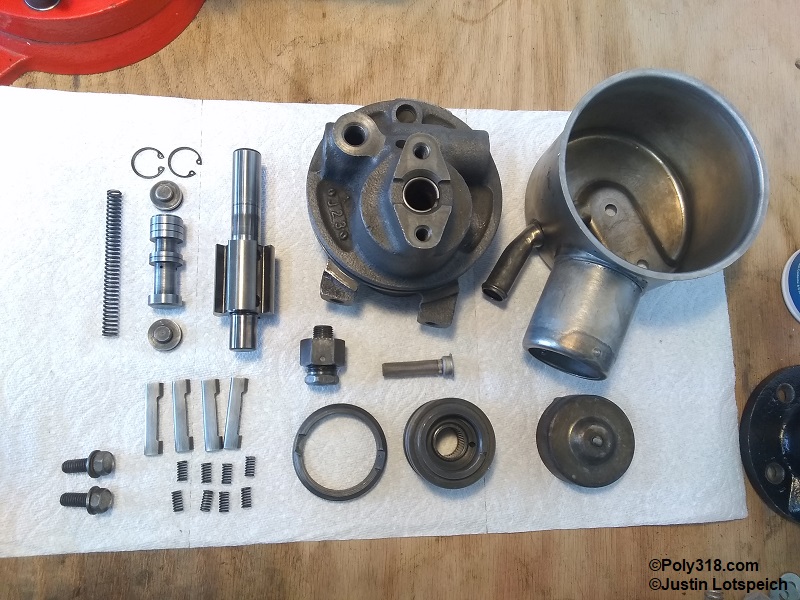
After cleaning the work area well, lay out all the cleaned parts (Figure 6a). It’s important to keep the assembly process very clean since any dirt/debris can easily damaged the rotating parts, bearings, and seals. Ensure all parts are free from lint and debris. At this point, I mask, prime, and paint the housing, reservoir, pulley, mounting brackets, and bolts since assembly will get oil on the bare metal and require cleaning again.
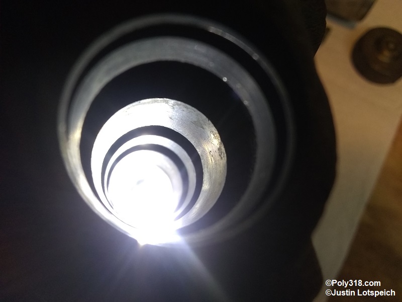
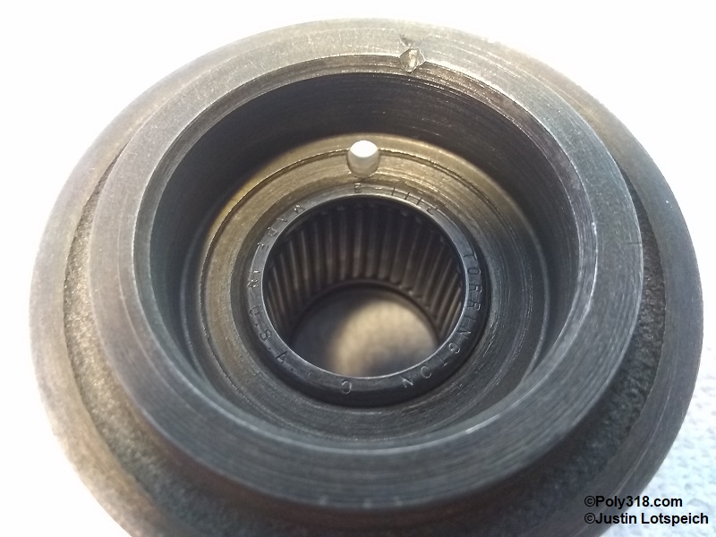
Using a light, inspect the flow control valve bore looking for galling, grooves, and burrs (Figure 6b). Light scratches and burrs can be smoothed with a brake wheel-cylinder hone. The bore in the pictured housing was free of issues (note: the discoloration at the 2:00 position was flash rust from cleaning that wiped off).
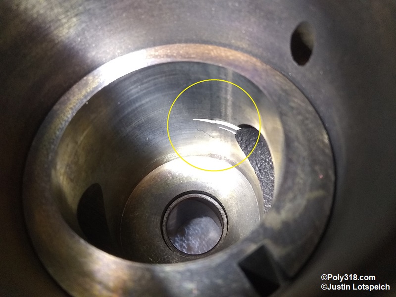
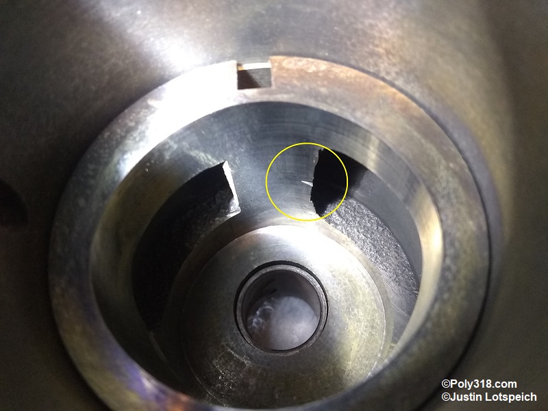
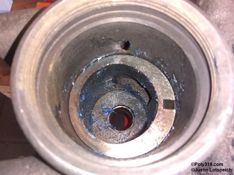
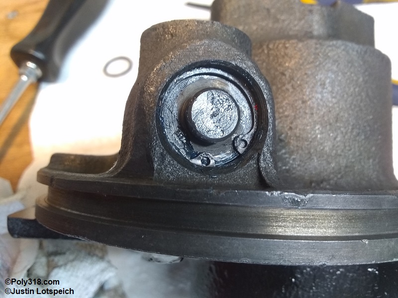
Inspect the rotor cam insert for damage including grooves, deep scratches, and corrosion (Figures 6c – 6d). If there is damage that will cause the fluid to leak past the slipper, the housing requires replacing. Note that one end of each inlet/outlet port has a factory machined groove (circled) that shouldn’t be mistaken for damage.
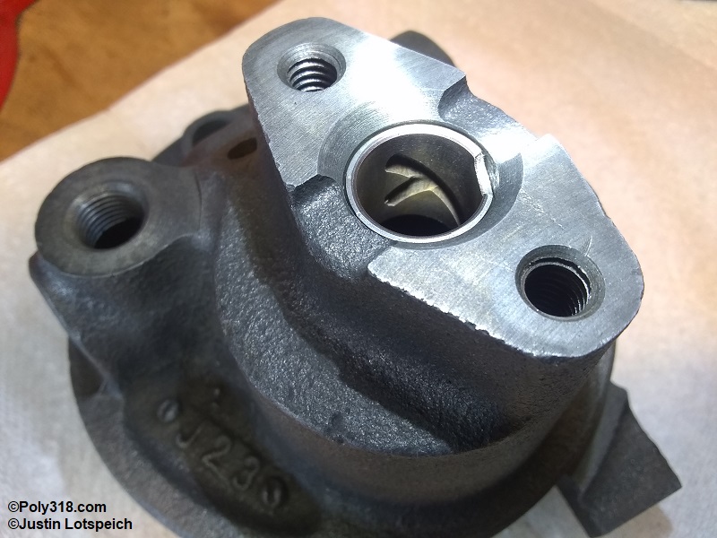
Inspect the rear rotor shaft bushing or needle bearing for excessive wear or damage (Figure 6e). If the bushing/bearing is excessively worn or damaged, replace it by driving it out with a drift from the cam-insert side and pressing in a new one. Note: The deep groove is for oiling and is normal.
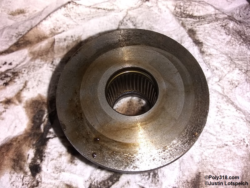
Inspect the outlet flare ferrule for excessive wear or damage (Figure 6f). It’s normal to see a uniform groove from the hose fitting. Excessive damage requires resurfacing or replacing the ferrule.
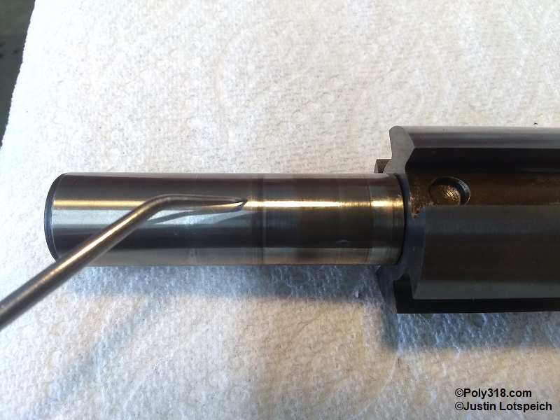
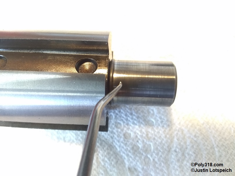
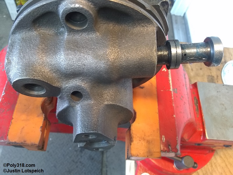
Lightly drag a mechanics pick across and parallel with the rotor shaft to inspect for wear valleys at the seal and bearing (Figure g6 – 6h). Visually look for galling and deep scratches. Light scratches where the needle bearing rides can be smoothed with 1,000+ grit crocus cloth, but don’t sand the shaft where the oil seal rides. Galling or deep scratches/grooves requires obtaining a replacement. While stained, the pictured shaft had no noticeable wear.
Inspect the rotor edges for missing chunks and burrs (Figure 6i). Small nicks from the machining process are acceptable, but the edge should be uniformly razor sharp. Any burs or rounded edges should be smoothed and sharpened with a whetstone against the sidewall of the groove where the springs rest and using 1,000+ grit crocus cloth on the outside of the rotor. The pictured rotor had no damage.
Visually inspect the needle bearing for damage including flaking, corrosion, and nicks (Figure 6j). Place a bare finger against the needles, and rotate the insert to spin the bearing. The movement should be smooth. If the movement is rough or any needles hang up, press out the bearing and install a new one. Do the same if there is a rear needle bearing. The pictured bearing was in great usable condition.
Inspect the flow-control valve piston’s outside surface for galling, grooves, and burrs (Figure 6k). Any burrs or small scratches can be smoothed with 1,000+ grit crocus cloth. Galling or deep scratches/grooves that run parallel and create a path for oil to leak past require replacing the piston. Run a clean drill bit through the holes by hand and blow them out with compressed air to ensure they are clear of debris.
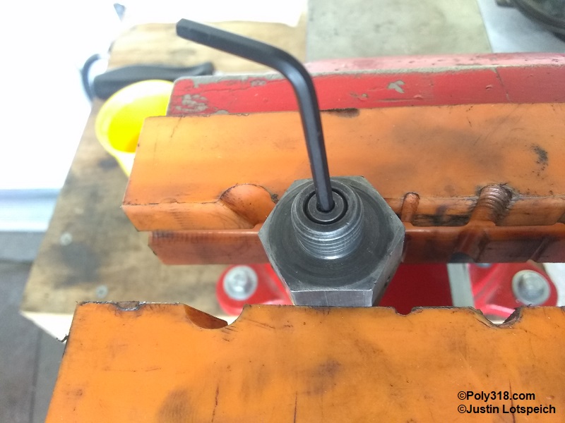
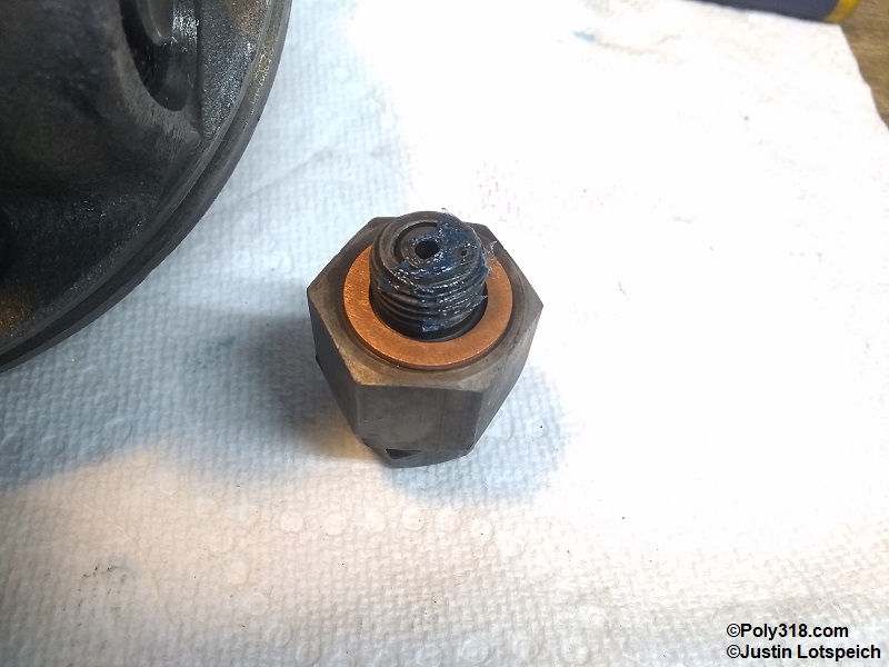
Testing the psi at which the relief valve opens requires a special in-line test gauge while the system is running. Depending on the specific vehicle, the maximum psi before the valve opens ranges from 850 – 1,300. With such high pressure, it isn’t possible to bench test the valve with compressed air. I insert a clean Allen wrench into the valve and compress the spring to physically check that it moves freely (Figure 6l). If the steering system has an issue after I place the pump into service, I check the system using the proper gauge setup and adjust the valve.
Power Steering Pump Kits and Rotor Assembly
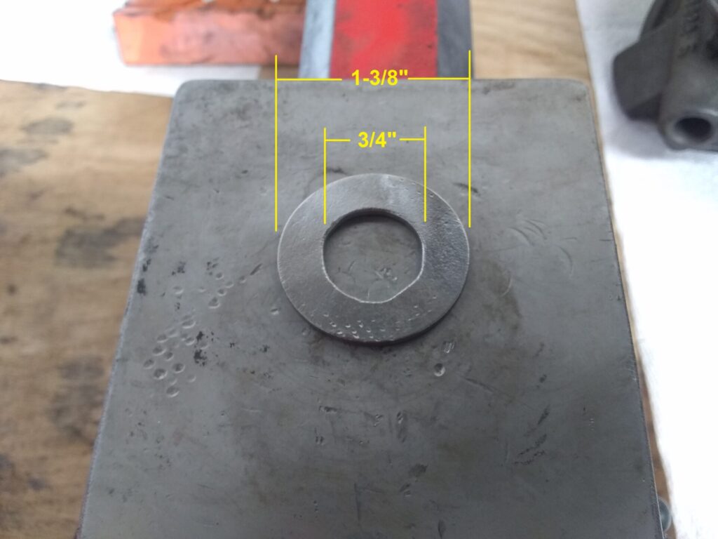
Before beginning assembly, fabricate a tool to assist with installing the rotor assembly (Figure 7a). Mopar long ago stopped producing the tool. For my 0.96 pump, I drilled out a washer to 3/4″ with an outside diameter of 1-3/8″. The 1.2 pump requires a washer at 7/8″ x 1-7/8″. Ensure the washer is free of burrs.
The proper kit depends on the pump manufacturer and model and should be confirmed. Upon receiving the kit, compare its seals, gaskets, and bearing(s)/bushing to the ones removed from the pump to ensure the parts are the correct replacements.
Federal Pump
Edelmann 7898: Seals and gaskets only.
Edelmann 7900: Seals, gaskets, and front shaft needle bearing.
Thompson (TRW) Pump
Edelmann 7897: Seals and gaskets only.
Edelmann 7899: Seals, gaskets, and front and rear shaft needle bearings.
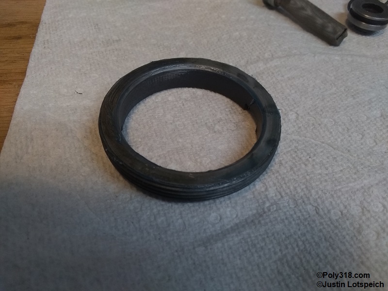
Place the bearing insert on a wood block covered with a clean paper towel or rag. Position the shaft oil seal square on the insert (Figure 7b). Using a bearing/seal driver, evenly hammer the seal in until it is flush with the face of the insert (Figure 7c). Warning: Do not damage the seal lip. Blow off any shavings that may have scraped off the outer metal sleeve of the seal.
Twist and push in the eight slipper springs until they are fully seated and even with each other (Figure 7d). Warning: The rotor edges are razor sharp. If required, use a pair of clean needle-nose pliers or the end of a wood pencil with the lead broken off. Don’t damage the springs. I’ve never had an issue pushing them in with my finger. Wipe clean a 12″ length of rebar tie wire. Bend a hook into one end. Wrap the wire around the rotor two or three times just loose enough for the wire to slide, and bring the wire through the hook toward the long end of the shaft (Figure 7e). This wire holds the slippers in during installation. Compress one spring with a finger, and slide the slipper over the spring. Note that the slippers MUST be oriented like in the photo with the notched side facing up when the rotor end of the shaft is to the right. If the notch is placed backwards, the pump will not build pressure. Slide the slipper underneath the wire, compress the second spring, and slide the slipper over the spring. Using a clean pocket screwdriver to stand the springs up when the slipper tries to bend them over helps with installation. Ensure all springs are upright when finished (Figure 7f).
With all slippers installed and the springs upright underneath the slippers, slide the washer tool over the shaft. Apply a liberal coat of assembly lube or power steering fluid to the rotor assembly including the rear shaft that rides in the bushing/bearing (Figure 7g). I prefer Dr. Tranny’s “Blue Light Tack Assemblee Goo” since it holds in place, isn’t as messy as fluid, and is formulated to dissolve into the fluid. Liberally coat the cam insert and rear shaft bushing/bearing with assembly lube (Figure 7h). Installing the rotor assembly I imagine is much like working a string puppet. Gently set the rotor assembly into the mouth of the cam insert. Use two clean, long screwdrivers to evenly press against the washer tool to begin pushing the rotor assembly down. At the same time, move the wire as necessary to allow the rotor assembly to lower while keeping the slippers compressed. If a slipper hangs up and begins tilting the washer, stop and apply force over just that slipper to square it even with the rotor. Once the rotor assembly bottoms out, remove the wire and washer tools (Figure 7i). When properly installed, the top of the four slippers should be even with the rotor, and the rotor and slippers should not protrude above the cam insert (Figure 7j).
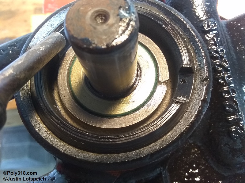
Install a new o-ring around the bearing insert. Liberally coat the o-ring, needle bearing, oil seal lip, and flat face of the insert with assembly lube (Figure 7k). Liberally lubricate the rotor shaft with assembly lube, and set the insert over the shaft carefully guiding the oil seal over the shaft and aligning the punch marks made before disassembly (Figure 7l). Ensure the punch marks align, and press the insert down by hand to start the o-ring into the bore. Place the pump housing on a wood block covered with a clean paper towel/rag. With a 1-1/4″ deep socket against the insert (NOT the seal), use a rubber mallet to gently drive the insert down far enough for three housing threads to show (Figure 7m). Note that the factory manual says to use a press for this procedure, but a mallet is fine here and won’t damage anything. Coat the face of the spanner nut that rides against the insert with assembly lube to stop the two from catching during torquing (Figure 7n). Use a drift to tighten the spanner nut until feeling firm resistance. Carefully tighten the nut until all three punch marks align (Figure 7o). Spin the rotor shaft by hand a few rotations. There should be some resistance from the slippers, but the shaft should rotate smoothly.
Measuring Power Steering Pump Rotor Endplay
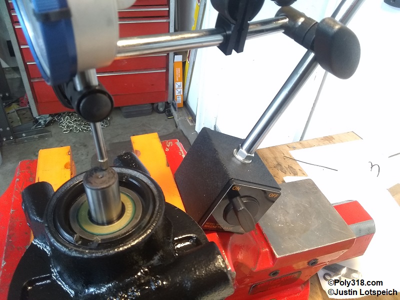
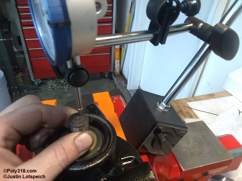
Wipe the rotor shaft clean, and push it down by hand as far as it will go. Set up a dial indicator parallel to the shaft, and zero it out atop the shaft (Figure 8a). Pull up on the shaft as far as it will move, and record the dial indicator reading (Figure 8b). The clearance should fall between 0.025″ – 0.030″. If the clearance is looser than 0.030″, the backside of the spanner nut, the front and/or rear end of the rotor, and/or the housing at the backside of the rotor is/are worn and require replacing. The pictured pump measured within spec at 0.027″.
Power Steering Pump Flow Control Valve and Relief Valve Assembly
Install new o-rings on each plug, and lubricate the o-rings with assembly lube (Figure 9a). Gently push in the plug on the end near the pressure relief valve port until it clears the circlip groove. Install the circlip. If after installation the plug is not up against the circlip, insert a clean drift or screwdriver into the bore and push the plug tight against the circlip (Figure 9b). Liberally coat the flow-control spring and valve with assembly lube. Insert the spring and valve into the end adjacent to the output port as pictured (Figure 9c). Insert a clean pocket screwdriver through the pressure relief valve hole, and try to move the spring to ensure it is seated in the plug well and cannot move around (Figure 9d). Insert the plug in the opposite end (adjacent to the discharge port), and push it in compressing the piston/spring until the circlip can be installed. Install a new copper washer over the pressure relief valve, lubricate the threads with assembly lube, and thread in the valve finger tight (Figure 9e). With the pump housing secured in a vise, torque the pressure-relief valve to 30 lb.ft. (Figure 9f).
Power Steering Pump Pulley Installation
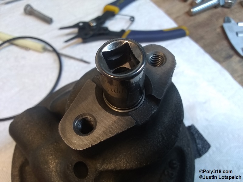
Prepare a shallow socket to support the backside of the rotor shaft. In this case, a 3/8″ drive12mm socket both covered the shaft and fit inside the housing (Figure 10a). Wipe off the shaft and the inside of the pulley hub with lacquer thinner or brake cleaner. Don’t get the cleaner on the oil seal lip. With the back of the shaft supported on the socket, tap the pulley onto the shaft with a rubber mallet just until it starts and holds in place (Figure 10b). Warning: Do not beat on the pulley with a mallet or hammer to fully install it. I place a 3/8″ washer over the hub to protect the hub from the press ram.
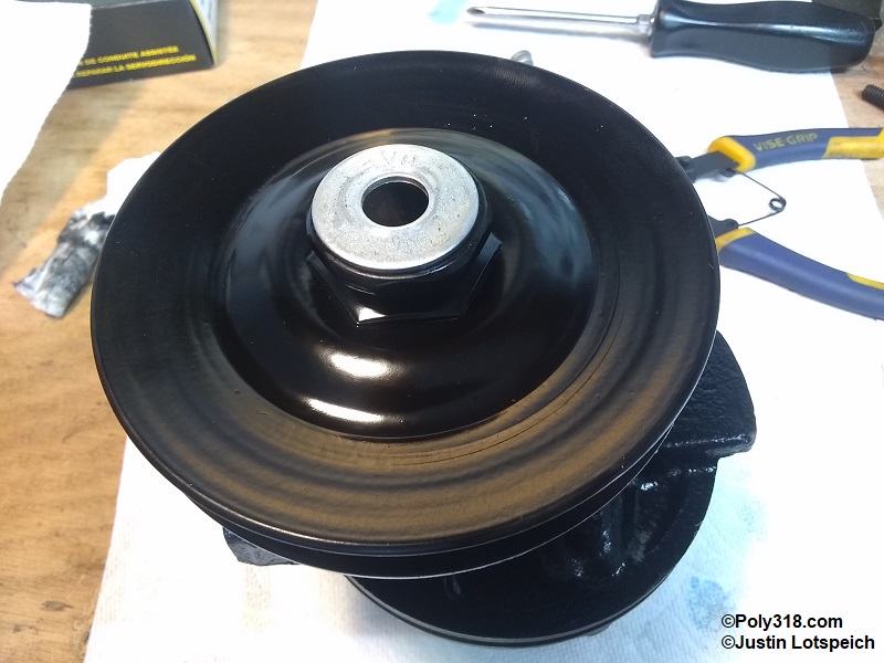
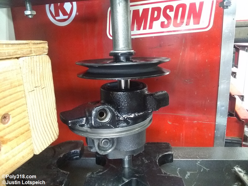
Set up the pump square in an arbor or hydraulic press with the socket supporting the rotor shaft at the bottom and not touching the housing (Figure 10c). Slowly apply pressure to the pulley. When I feel a change in the resistance when the pulley gets closer to the housing, I back off the ram and check until the hub is flush with the shaft end. These pulleys take a lot of pressure to install, so go slowly and check.
Note: If the shaft end is threaded, an installation tool can be used in place of the press. The pulley is properly installed when the hub is flush with the rotor shaft (Figure 10d). Touch up the paint that is damaged/removed during pressing.
Power Steering Pump Reservoir Installation
Blow off the pump with compressed air, and confirm there is no debris. Install a new reservoir o-ring and lubricate it with assembly lube (Figure 11a). Apply assembly lube around the inside opening of the reservoir. Apply tack assembly lube or a dab of Vaseline to the reservoir to hold the rear gasket in place (Figure 11b). Note that some pumps use rubber ring seals in place of the paper gasket. With the pulley face-down, align the back reservoir bolt holes and the pump holes, and gently press the reservoir onto the pump. Install the mounting brackets to the side of the pump finger tight, and then install the rear bolt(s). Torque the rear bolt(s) first to 15 lb.ft. and then the side bolts to 30 lb.ft. Install the filler cap and return screen (Figure 11c – 11f).
Assessing the Power Steering Pump in Service
At this point, I place the pump into service and analyze the steering action at low rpm and speed and at higher rpm and speed. If the steering is problematic, I install in-line gauges to measure the different pressures per the factory manual. Know that the rotor assembly is within spec since I checked it during rebuild, the first place I would look for an issue is the pressure relief valve. If the valve is opening at a lower or higher psi than the specification, I would remove the pump, remove the reservoir, remove the pressure relief valve, and adjust the valve until pressure is within specification (tightening the smaller nut increases the pressure while loosening the nut decreases pressure). I would peen the valve housing to lock the nut.
Conclusion
The Thompson (TRW) and Federal power steering pump models 0.96 and 1.2 used on 1960’s vehicles are simple designs and, aside from the pulley remover and press, don’t require specialized tools to disassemble and assemble. The largest obstacle is the lack of new replacement hard parts such as the slippers, springs, rotor, housing, and reservoir. Damaged or worn parts require purchasing another core and hoping its parts are usable. Sometimes, however, the pump internals are in great condition like the one I rebuilt for this video, and in those cases a $10 – $20 kit gets the job done and the power steering pump back in service for many more miles.