Driveline Dynamics
and
Setting Rear End Pinion Angle
Introduction
There is a lot of misinformation and vague factual information both on the internet and in printed magazines/articles regarding driveline dynamics, measuring u-joint operating angles, and setting rear end pinion angle, so I hope in the article I can clear up the process and provide useful examples for those restoring or modifying their driveline and suspension. This article focuses on u-joint drivelines with leaf spring, four-link, and ladder bar configurations. Many resources throw around vague “rules” such as the engine/transmission must be set at or below 3° negative slope, u-joint operating angles must be set at 1° and absolutely never over 3°, rear axle wrap on leaf spring cars ranges from 5° – 10°, and a bunch of other unexplained and often incorrect information. When I first began messing around with suspension and swapping rear ends that required new spring perches and therefore a new pinion angle, I found myself swimming in this vague and conflicting information. Throughout the years working in a body shop and building multiple custom chassis, I have gained an understanding that might be worthwhile to others. In the following sections, I summarize the basics and how to deal with less-usual situations that I have never seen covered in popular publications on the subject.
Terminology
Let’s start with some terminology for all the different considerations when setting up the driveline:
Output Shaft Angle: The angle in degrees of the transmission output shaft in relationship to level ground. This measurement can be taken off the front of the crankshaft pulley, the face of the transmission output shaft flange, or the flat face of the slip yoke installed on the output shaft.
Pinion Angle: The angle in degrees of the rear end pinion in relationship to level ground. This measurement can be taken off the face of the pinion flange.
Drive Shaft Angle: The angle in degrees of the drive shaft in relationship to level ground. This measurement is taken off the bottom or top of the drive shaft tube or a string-line ran from the output shaft to the pinion shaft for cars without driveshafts installed.
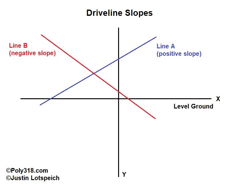
Slope: The slope of the angle is either positive or negative based off an X/Y axis when viewed from the left (driver) side of the vehicle (Figure 1). In Figure 1, line “A” is a positive slope and line “B” is a negative slope.
U-joint Operating Angle: The angle in degrees the u-joint will operate at, which is comprised of both the output shaft and drive shaft angles for the front u-joint and the pinion and drive shaft angles for the rear u-joint. I will discuss calculating this angle later.
Axle Wrap: The degree that the pinion rotates on the rear axle centerline under load. This rotation varies depending on the type of rear suspension and is extremely difficult to calculate but can be limited or preset when using 4-link, ladder bars, traction bars, and other types of mechanical stops.
Intake Angle: The angle of the intake manifold carburetor mounting pad from front to back in relationship to level ground. Note that on carbureted intake manifolds, this angle is not the same as the output shaft angle, which I discuss later.
Principles of Driveline Angles
In summary, the purpose of properly matching u-joint operating angles is to remove harmonic vibration that results from the u-joints rotating at different speeds and to keep u-joint operating angles within their rated limits of drive shaft rpm. Multiple chassis and suspension components influence these angles including type of rear suspension, rear leaf spring arch, rear coil spring height, rear spring rate, the elevation of the rear axle in relationship to the chassis, the elevation of the transmission output shaft in relationship to the chassis, the angle of the pinion, and the angle of the of the transmission output shaft. Tire size and vehicle rake does not impact the front and rear u-joint operating angles once set, although rear tire size does impact drive shaft rpm at a certain vehicle speed needed for calculating the angles, which I discuss more later.
While it may not seem obvious, if the front and rear u-joints are set at different operating angles and/or the output shaft and pinion set at different slopes, the u-joints rotate at different speeds and cause vibration along with eating up engine power through friction (Figure 2 is a good video demonstration). I’ll provide some general rules before moving on to real-life examples:
Rule A: Output Shaft and Pinion Slopes Must Match at Normal Driving Conditions
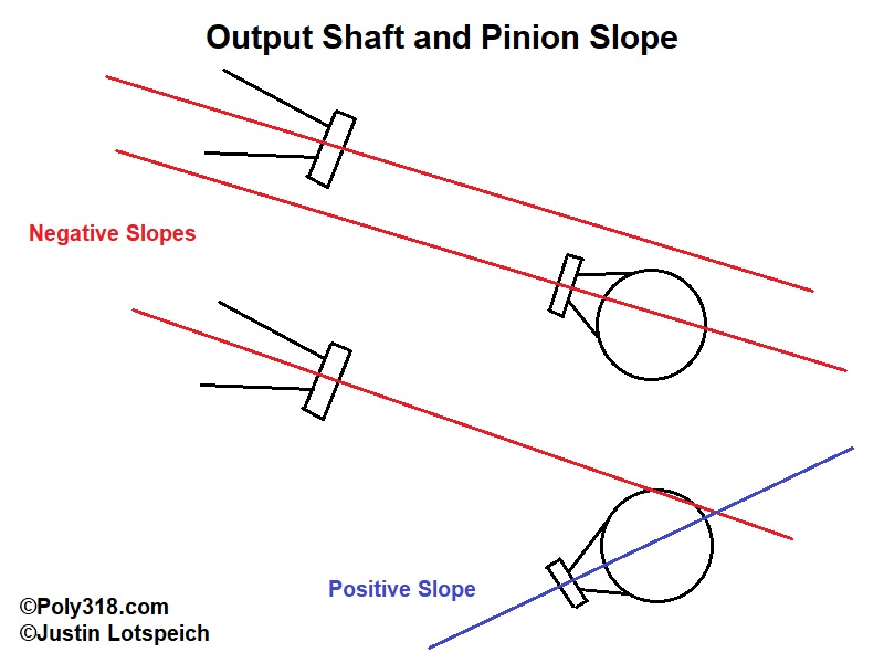
The “at normal driving conditions” is almost always left out of the discussion in literature and online, causing much confusion. In almost all cases, the output shaft will be at a negative slope (remember Figure 1 slope definitions). Along with crankshaft harmonics, the engine and transmission are angled down in the back to help force air pockets in the cooling system into the radiator rather than creating an air pocket in the block/heads/intake. The pinion slope must match the output shaft slope being careful not to get confused with if the pinion points toward the ground (nose down) or toward the floor pan (nose up). I’ve read on many forums people telling others that since the output shaft is pointing toward the ground, the pinion must point toward the ground, which is a completely incorrect assumption without doing the math and considering all the variables. Referring to the slope lines in Figure 1, examine Figure 3. If the output shaft and pinion slopes must match and the output shaft point toward the ground (a negative slope), then a negative slope output shaft requires the pinion be set with a negative slope with the nose-up.
Why did I specifically say “at normal driving conditions” in this rule? It is incorrect to set the pinion angle based off where all the variable angles are with the vehicle at rest. When setting pinion angle and therefore slope, one must build in wiggle room for axle wrap when the axle is under the load it will see under normal sustained driving conditions. This load will vary depending on the car’s purpose. For example, a full drag car should be calculated for constant hard acceleration with the maximum amount of constant axle wrap, whereas a street car should be calculated for more of a sustained cruising load at the most often used MPH, such as 50 MPH, after the maximum axle wrap at takeoff has decreased. Whether a race or street configuration, the pinion slope with the car at rest is not of concern; it’s the pinion slope under load that matters. For example, if the necessary pinion angle under load is low enough of a negative slope (nose up), the pinion might need to be set at a positive slope (nose down) when the car is at rest so that when the car is driving down the road at 60 MPH the axle wrap rotates the pinion up to the desired negative slope (nose up). If the pinion angle under load is high enough of a negative slope (nose up), the pinion might be set at a negative slope (nose up) when the car is at rest. We’ll get into these calculations shortly.
Rule B: Front and Rear U-joint Operating Angles Must Match within 1° at Normal Driving Conditions
Once again, “at normal driving conditions” is almost always left out of the discussion. In order for the front and rear u-joints to rotate at or very close to the same velocity and cancel out harmonic vibrations, they must be set within 1° of each other during normal driving conditions. Similar to my comments regarding the slopes matching, these angles may not necessarily match when the car is at rest but should within 1° when the car is at its most common operating load. At rest, a street car that requires 3° rear u-joint operating angle cruising on the highway at 60 MPH may end up having an operating angle of 4° at rest if the pinion slope is set lower than it will be under load to compensate for axle wrap.
Rule C: U-joint Operating Angles Must Not Exceed Their Drive Shaft RPM Design Limits
Not to be confused with engine RPM, u-joints are designed to operate up to a certain angle at a certain drive shaft RPM. There are two ways this RPM should be calculated: at the engine’s redline RPM and at the vehicle’s maximum speed, which I discuss shortly.
Rule D: The Drive Shaft and U-joints Must Have some Angle Built In
None of these components should be dead level at 0°. While the lower the angle the better for limiting engine power waste through friction and for u-joint life expectancy, some angle should be maintained for proper dynamics and balance.
Next, we’ll cover how to calculate all these angles and run through some real-life examples.
Figure 2: Video on Drive Shaft Velocity with Varying U-joint Operating Angles
Calculating Carburetor, Output Shaft, Drive Shaft, Pinion, and U-joint Operating Angles
When setting up the driveline, the vehicle should be resting under its own weight with the amount of gas in the tank that it will have on average. The rear axle and output shaft elevations in relationship to the chassis should also be set exactly where they will normally rest, as in you should have the front and rear springs installed and adjusted. If you cannot crawl underneath the vehicle and you don’t have a drive-on lift or pit, take a measurement at the front of the rocker panel to the ground and the rear of the rocker panel to the ground with the car at rest. Place the vehicle on jackstands located under the rear axle and under the chassis at the front maintaining the same rake that you measured. For example, if the car resting on the ground has the front of the rocker panel 8″ off the ground and the rear of the rocker 10″, adjust the jackstands to where when the car is in the air the front of the rocker panel is 2″ lower than the rear of the rocker panel.
-Carburetor Mounting Pad Angle:
Place a protractor across the carburetor mounting pad to get the angle from front to back of car (I recommend a 6″ digital protractor or torpedo level that reads digits 00.00° with a “hold” option). This angle should be as close to 0° as possible since it impacts carburetor float level. The pad is designed at a different angle than the crankshaft centerline so that when it is level, the crankshaft/output shaft will have some negative slope to them for the purpose of harmonics and cooling system air pockets as previous discussed. If necessary and possible, adjust the mounting pad angle to or close to 0° by shimming the transmission rear mount or modifying the transmission crossmember.
-Front U-joint Operating Angle:
Take the angle measurement of the transmission output shaft by placing the protractor vertically from top to bottom of the output shaft flange, slip yoke face, or across the front of the crankshaft pulley. Write down this angle as the “output shaft” and note if it is a positive or negative slope viewing from the left (driver) side of the vehicle (see Figure 1 for slope definitions). Contrary to what many online resources say, this angle does not necessarily have to be under 3°, so hold off on any adjustment until you work through all the other calculations and considerations.
Place the protractor on the bottom of the drive shaft running front to back, record this angle as the “drive shaft”, and note the slope as negative or positive. If the vehicle doesn’t have a drive shaft yet, use clamps to fasten a piece of string-line on the output shaft/flange and on the rear axle flange making sure to clamp the string taut and the same distance away from the center of the output shaft and pinion shaft. Carefully lift the protractor up against the string line to measure the angle making sure the level does not distort the string.
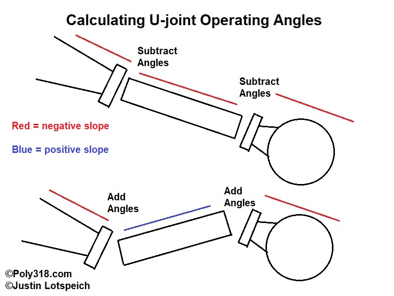
Now we get into the math. Referring to Figure 4, if both the output shaft and drive shaft slopes (not angles) are the same–whether that is a positive or negative slope–subtract the smaller number from the larger number and write this number down as the “front u-joint operating angle.” For example, if the output shaft is 5° negative slope and the drive shaft is 1° negative slope, the u-joint operating angle is 5 – 1 = 4°; if the slopes are opposites–such as one slope is negative and the other is positive–add the numbers to find the u-joint operating angle. For example, if the output shaft is 3° negative slope and the drive shaft is 2° positive, the u-joint operating angle is 3 + 2 = 5°. Do not use negative numbers for negative slopes, as in it is incorrect to calculate this angle as -3 + 2 = -1° in this example. If one of the measurements is 0°, adjustments need to be made to ensure both the output shaft and drive shaft have some angle built in for proper dynamics.
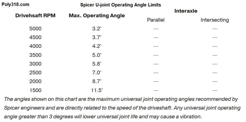
Here’s where a lot of misinformation comes into play and requires some deeper discussion. By 99% of the information on the internet particularly regarding classic cars, the 4° u-joint operating angle in the example above will cause terrible vibrations and destroy the u-joint. Not necessarily, evident from the millions of lifted trucks and off-road vehicles safely and comfortably cruising down the highway with operating angles far above 4°. Even some factory trucks have greater u-joint operating angles than 3°. Drive shaft rpm is the critical factor in determining the safe u-joint operating angles, not a set number for all vehicles no matter the context. Figure 5 shows Spicer’s published maximum operating angles, but keep in mind these are very conservative figures that even automotive manufacturers and drive shaft builders, particularly in trucks, often ignore. There’s much to be learned here from the off-roaders among us since many of them run u-joint operating angles upwards of 8° at highway speeds without vibration or premature u-joint failure. In practice, 10° seems to be the upper limit before harmonic vibrations according to multiple drive shaft builders I’ve consulted, but keep in mind that the higher the angle, the less drive shaft RPM the u-joint can handle and the more engine power is lost through friction.
Let’s use an example to help clarify how a 4° u-joint operating angle may work just fine in a car. Let’s say for whatever reason the transmission cannot be shimmed and the rear end cannot be raised or lowered to change drive shaft angle, so we are stuck with a 4° u-joint operating angle. Looking at Figure 5, Spicer claims a 4.2° operating angle is good to 4,000 drive shaft rpm, so let’s use that number. What is the highest engine rpm the engine will ever practically see? For most poly A-blocks with stock or mild cams, peak horsepower comes in by 5,500 rpm. For high-performance A-blocks, 6,500 with the hottest engines up at 7,000. However, keep in mind that none of these vehicles will ever see their maximum engine rpm in the highest transmission gear unless it’s a land-speed car. It is reasonable that they would see this maximum rpm in second gear, so we will use the transmission’s second gear ratio for the following calculation:
Calculating Drive Shaft RPM from Engine RPM: Engine rpm divided by transmission gear ratio (second gear in our example). Let’s say our engine redlines at 6,500 rpm and we are running a TorqueFlite 727 with a 1.54:1 second gear. The equation is 6500/1.54 = 4,220 drive shaft rpm. This rpm is just outside Spicer’s limit, so we are good with a 4° u-joint operating angle in this engine RPM example, but we need to now consider driveshaft RPM in relationship to vehicle MPH.
Calculating Drive Shaft RPM from Vehicle MPH: Now let’s check the drive shaft speed at the maximum vehicle speed. For this calculation, let’s say the car might see some 1/4 mile track time at 100 MPH top speed at the end of the track. We need to perform a series of calculations:
Tire circumference in feet = (tire height x 3.14 pi) / 12 inches
Tire rotation per mile = 5280 feet per mile / tire circumference in feet
Drive shaft rotation per mile = Tire rotation per mile x rear axle gear ratio
Drive shaft RPM = vehicle MPH x rotation of drive shaft per mile / 60 minutes
For our example:
Tire circumference in feet = (26.5 inches x 3.14 pi) / 12 inches = 6.93 feet
Tire rotation per mile = 5280 feet per mile / tire circumference in feet = 5280 feet / 6.93 feet = 761.90 tire rotations per mile
Drive shaft rotation per mile = Tire rotation per mile x rear axle gear ratio = 761.90 tire rotations x 3.54 gear ratio = 2697.13 revolution per mile
Drive shaft RPM = (rotation of drive shaft per mile x vehicle MPH) / 60 minutes = (2697.13 revs per mile x 100 MPH) / 60 = 4,495 drive shaft RPM
Putting all these calculations together for our example, we’ve found that at the highest engine rpm of 6,500 in second gear, the drive shaft will spin at 4,220 rpm barely outside Spicer’s recommended maximum. At the highest vehicle speed of 100 MPH with 26.5″ rear tires and 3.54:1 gears, the drive shaft will spin at 4,496 RPM. Looking at Figure 5, the maximum RPM for a u-join operating angle of 4° is around 4,000 rpm, so we are slightly outside Spicer’s range when considering vehicle MPH. If one wants to go off the Spicer limits, then the output shaft and/or drive shaft angles would need to be adjusted to decrease the u-joint operating angle, the engine redline would need to be decreased, or the tire size and rear gear ratio would need to be changed to lower drive shaft RPM at 100 MPH for our example. However, practical objective and anecdotal evidence from professional drive shaft builders who have spun up hundreds of thousands of drive shafts combined suggests the Spicer maximum operating angles are kept purposefully low to where in practice this 4° u-joint operating angle with this vehicle’s specifications would work just fine and safely without vibration or premature failure.
-Pinion Angle:
Back to our steps in setting pinion angle, let’s stay with our example of an output shaft at 5° negative slope and the drive shaft is 1° negative slope with a front u-joint operating angle of 4° (5 – 1 = 4).
If I am installing a new or swapped rear end with loose spring perch pads that need welding such as the Ford 8.8″ rear end in my 1956 Dodge coupe, I center the rear axle side to side, confirm proper wheelbase, and snug down the axle on the spring perch pads and leaf springs using the u-bolts with enough tension that I can still rotate the axle with a mallet but it will stay where I put it. For existing axles whose spring perch pads are already welded, I use rear axle metal shims between the pad and leaf spring to change the pinion angle.
As I explained in detail above, the rules are that the pinion slope must match the transmission output shaft slope and the rear u-joint operating angle must match the front u-joint’s within +- 1° during normal operating conditions. For our example, the output shaft slope is negative, so the pinion slope must be negative (nose up) during normal operating conditions. The front u-joint operating angle is 4°, so the rear u-joint operating angle needs to fall between 3° and 5° during normal operating conditions. Let’s say this car will likely see an average street cruising speed of 50 MPH around town, so the axle wrap won’t be much compared to wide open throttle. There is no precise way to determine axle wrap since there are many variables difficult or impractical to measure. The only way to measure axle wrap would be to strap a protractor to the axle housing, strap a video-recording device to the underside of the vehicle facing the protractor, and go drive at a steady 50 MPH. The amount of bouncing around in the suspension would likely give an inaccurate reading anyway, so we are left with approximation based off drive shaft builders’ observations. After discussing axle wrap with multiple drive shaft builders, the consensus is that about 1° – 2° is the most a leaf spring rear end would see at a sustained 50 MPH with new leaf springs. Old or soft leaf springs would see more wrap. Four-link, ladder bar, and rear axles with traction bars will have less axle wrap and can be limited through adjusting the components. These components should be inspected for how much flex they provide in the bars and bushings and an axle-wrap conclusion built off that inspection.
Here is yet another area where online resources can really screw someone up since many articles say to factor in a whopping 5° – 10° of axle wrap for leaf springs, which is a wild range considering the front and rear u-joint operating angles need to be within +- 1° of each other. In the case of our example, I need 3° – 5° of rear u-joint operating angle with the pinion at a negative slope (nose up) at a sustained 50 MPH. If I listened to those saying to account for 5° – 10° axle wrap, I’d need to set the pinion angle at 3° positive slope (pinion nose down) so that when the axle wrapped up 7° my front and rear u-joint operating angles would match at 4° +- 1° with the pinion slope at the matched negative slope. But what if the axle only wraps 2° like drive shaft builders claim? My pinion angle would be at 1° of positive slope (nose down). The rear u-joint operating angle would be 4° outside the +-1° limit, and the pinion slope would be positive and not match the transmission output shaft’s negative slope. This scenario would definitely cause severe harmonic vibrations and premature wear on the u-joints.
Following multiple drive shaft builders’ recommendations for leaf spring rear suspension, I recommend setting the pinion angle at 2° less than the front u-joint angle with the assumption that the axle will wrap up between 1° and 3°. For our example of a front u-joint operating angle of 4°, setting the pinion angle at 2° with negative slope would keep me within the 4° +-1° rear u-joint operating angle at 50 MPH if the axle wraps up 1° – 3°.
For another practical example for leaf spring rear suspension, let’s say the transmission output shaft is a negative slope and the front u-joint operating angle is 2°. In this situation, I would set the pinion angle to 0° expecting an axle wrap of 1° – 3° would bring the pinion angle up to a negative slope (nose up) that matches the output shaft, and the rear u-joint operating angle would be 1° – 3°, within +-1° of the front’s 2°.
Realistic Example from My 1956 Dodge Coupe
I know I just covered a lot of material, so I want to run through one last practical example taken directly from building my 1956 Dodge coupe. I gutted the engine, transmission, and suspension of the car to install a 1996 Dodge Dakota front clip and 2001 Ford Explorer 8.8″ rear axle and new custom leaf springs. I also installed a poly A-block 390 stroker engine and TorqueFlite 727 transmission. Essentially, I was starting from scratch and had to set the transmission output shaft angle and rear pinion angle before I could weld the new spring perch pads to the rear axle housing. I also had no drive shaft and needed to measure that to have one made.
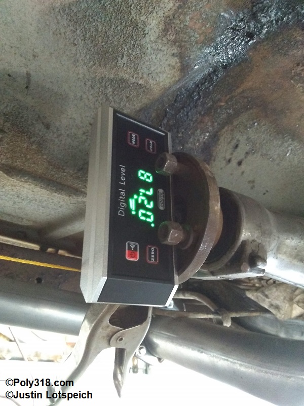
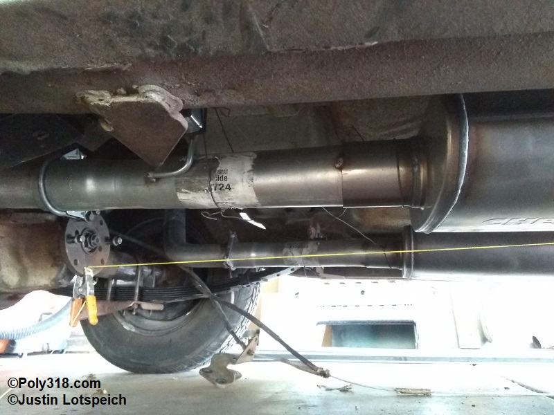
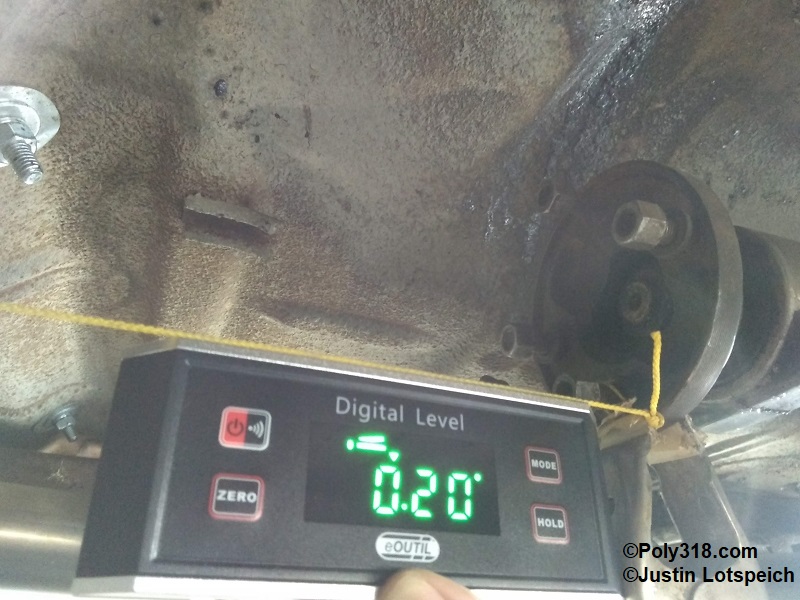
Since I fabricated the engine and transmission mounts, I was able to set the intake pad level at the vehicle rake I desired, which placed the output shaft at 2.8° negative slope (Figure 6a). Note that the digital protractor is measuring based off 90° vertical, so (90 – 87.2) = 2.8°. With the rear axle u-bolts tightened just enough to hold the housing from rotating on its own but allowing me to rotate the housing using a mallet, I adjusted the pinion angle to 2.8° negative slope (nose up) in order to measure my drive shaft angle where it will be under normal driving conditions of sustained 50 MPH. I measured out from the transmission output shaft center and clamped a string-line to the flange. I measured out from the pinion shaft center the same distance as the output shaft flange and clamped a taut string-line to the pinion flange (Figure 6b). I carefully brought the protractor up to the string and measured the drive shaft angle at 0.20° with negative slope (Figure 6c). I’d ideally like a little more angle in the drive shaft, but I wasn’t able to raise the transmission any more before hitting the body tunnel or lower the rear axle (via longer shackles or more arch in the leaf springs) since the car was at the rake I desired. Now that I had the necessary angles, I did the math:
Transmission output shaft angle: 2.8° negative slope
Drive shaft angle: 0.20° negative slope
Front U-joint operating angle: 2.8 – 0.20 = 2.6°
Armed with the front u-joint operating angle, I calculated where I needed to set the pinion angle. The custom rear leaf springs are stouter than stock, so I don’t anticipate more that 2° of axle wrap. If I find that I get more axle wrap, I plan on fabricating traction bars that will allow me to lock out axle wrap. I did the pinion angle math:
Transmission output shaft slope: negative
Front U-joint operating angle: 2.6°
Required pinion angle building in 2° axle warp: 2.6 – 2 = 0.6° negative slope (nose up)
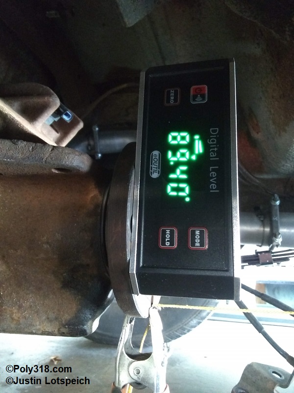
Using a mallet, I tapped the pinion until I had the flange set at 0.6° negative slope nose up (Figure 6d). Note that as with the output shaft, the protractor is measuring from 90° vertical, so 90 – 89.4 = 0.60°. I snugged down the u-bolts and checked the angle again to find that the axle rotated slightly, so I loosened the u-bolts and adjusted the pinion angle until it remained at 0.60° with the u-bolts snugged down.
With all the angles calculated and the pinion angle set, the output shaft and pinion slopes match at negative slope (output shaft down, pinion nose up), the front U-joint operating angle will be 2.6°, and the pinion angle be at between 1.6° and 3.6° at sustained 50 MPH, within +-1° of the front u-joint operating angle depending on axle wrap. At this point, I tack-welded the spring perch pads to the axle housing in preparation for removing the housing to finish the welds.
Conclusion
I hope that by going through the principles, math, and practical examples that driveline dynamics and pinion angle are clearer. After reading this article, we can see how making some modifications after setting u-joint operating angle and pinion angle will negatively impact the settings. For example, moving the rear axle elevation in relationship to the transmission output shaft elevation (modifying spring arch or coil spring height, installing lowering blocks, modifying shackle length, and/or locating the axle housing above/below the leaf spring) will change the drive shaft angle and therefore change the front and rear u-joint operating angles. One should plan on checking and resetting these angles as necessary. If someone installs a device to limit axle wrap (e.g. traction bars), he should ensure there is enough preset slop in the device to let the pinion angle rotate enough to align on the same slope as the output shaft and put the rear u-joint operating angle within +-1° of the front u-joint’s operating angle since it was set taking into account axle wrap without a limiting device. Changing the front suspension elevation with different springs and changing front or rear tire height will not impact the u-joint operating angles since all these components (output shaft, drive shaft, pinion) are fixed in elevation relative to the chassis and will change angle evenly together if the chassis is lowered or raised in relationship the ground. Changing the rear tire height and/or gear ratio will impact the drive shaft RPM at vehicle speed, which may put u-joint operating angles outside of their limits.
While it would be a long list to thank those throughout my life who have helped hone my craft building and tuning chassis, I want to put in a plug for my friend Shawn Wood of Tom Wood’s Custom Drive Shafts who builds excellent drive shafts for off-roaders and ships them worldwide. His work with off-road vehicles and the conversations I’ve had with him on driveline dynamics and particularly challenging angle situations have taught me a great deal through the years.