Chrysler, DeSoto, Dodge, Plymouth
Convert from PowerFlite & A466 Transmission
to TorqueFlite A727
Introduction
For my performance 1956 Dodge coupe build, I wanted to move away from the factory PowerFlite two-speed automatic transmission and use a TorqueFlite (or truck LoadFlite) A727, but I wanted to retain the push-button shifting. In this article, I detail how I went about converting to an A727, but the article applies to other 1955 – 1961 Forward Look Mopars with push-button shifting. For the purposes of this article, I assume you have made the necessary modifications to install the A727 transmission in the car/truck, including modifying or fabricating the transmission crossmember. I detail these modifications on the 1956 Dodge in another article about the 1996 Dodge Dakota front suspension swap. Swapping a TorqueFlite or LoadFlite A727 into a 1955 – 1961 Forward Look Mopar is certainly a project but not insurmountable. I’ve tried to lay out the different options, obstacles, and other considerations of the process, but each project will differ in some way.
Shifter Mechanism
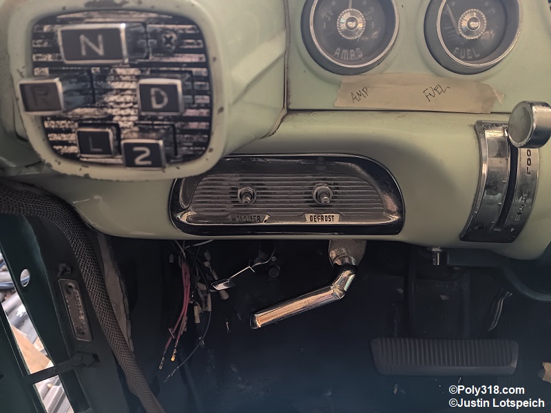
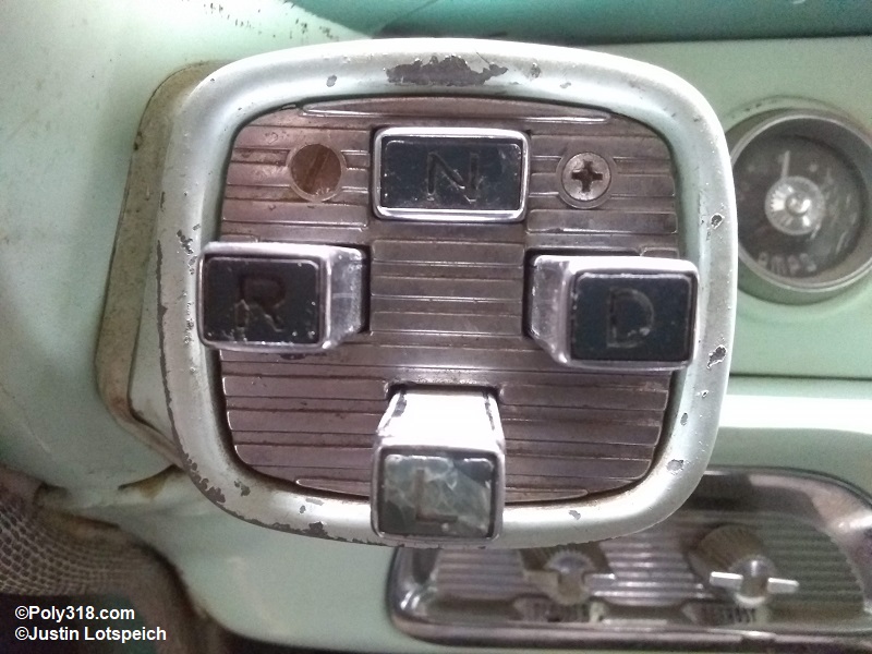
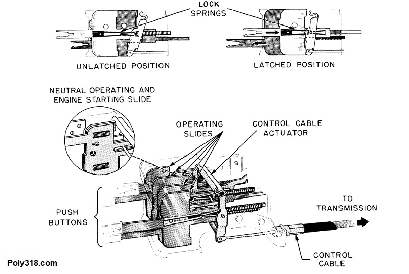
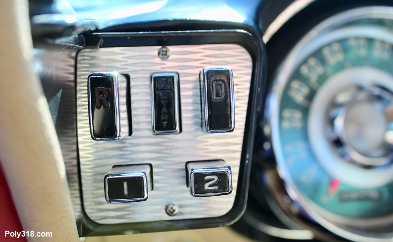
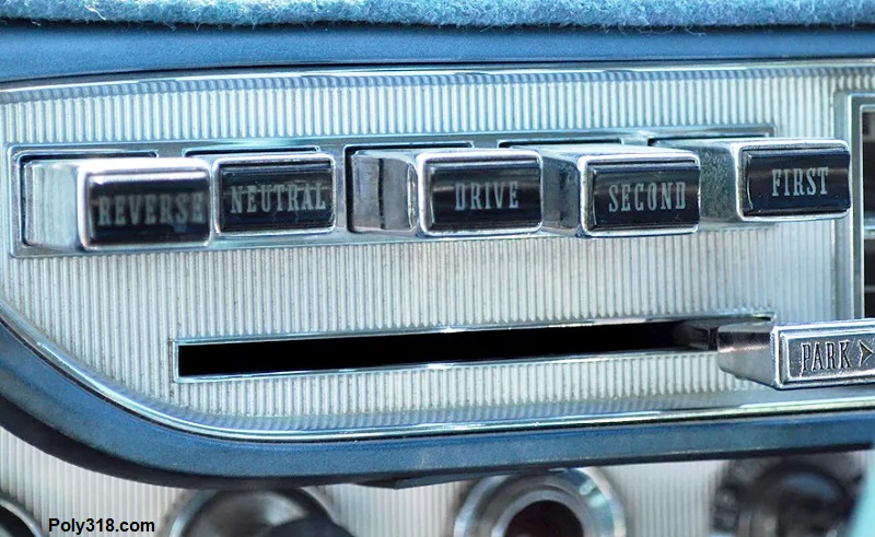
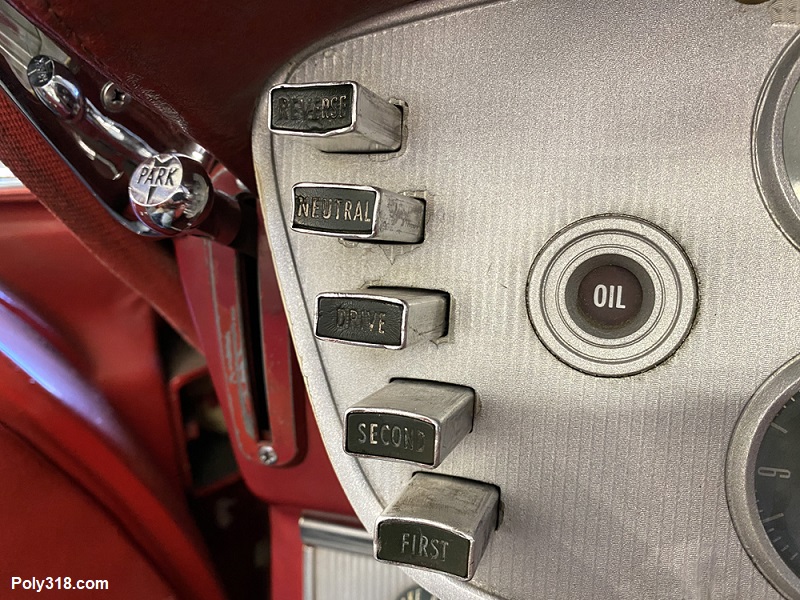
The 1956 Dodge originally had a PowerFlite two-speed transmission, so I had to address the shifter (Figure 1a). The solution was to swap out the two-speed shifter mechanism with a mechanism from a 1956 – 1961 car or truck equipped with a TorqueFlite/LoadFlite A466 three-speed or a 1962 – 1964 car or 1962 – 1965 truck equipped with a TorqueFlite/LoadFlite A727. My understanding is that aside from minor changes to the neutral-safety and backup light switches and the addition of a parking lever on 1963 – 1964 mechanisms (which can be removed), almost all of the push-button shifting mechanisms from 1956 – 1964 function the same with a RN321 pattern and are candidates for the swap (Figure 1b). The exception is an oddball mechanism marked with a painted “305” on the side that has a reverse pattern RN123 used only on 1964 Chrysler 300 that had a corresponding valve body. this 1964 Chrysler 300 mechanism will not work with other A727 or A466 transmissions since it places the transmission’s shifter rooster comb in the incorrect positions. To clarify–since at a glance one might assume the mechanisms changed because the button configurations changed throughout the years including clusters (Figure 1c), horizontal (Figure 1d), and vertical (Figure 1e) configurations–the shifter mechanisms themselves remained the same with the buttons changing to mate to the mechanism. I ended up using a 1959 Plymouth three-speed mechanism part number 1673906.
Shifter Adjustment
Importantly, use the shifter adjustment instructions from the service manual of the year of the transmission and not the year of the shifter mechanism. The 1962 – 1964 cable is adjusted by placing the shifter mechanism in reverse, pushing the cable into the transmission housing, making the adjustment per the manual, and locking the adjuster wheel. The 1965 valve body differs from the 1962 – 1964 where the park position is after the reverse position, so the 1965 shifter cable is adjusted by placing the shifter mechanism in first gear, pulling out on the cable, making the adjustment, and securing the adjuster wheel. If you adjust the 1965 transmission using the 1962 – 1964 instructions, the shifter will not function properly, and vice versa.
Shifter Buttons and Face Plate
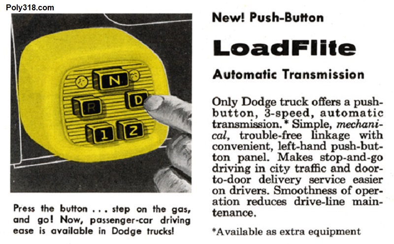
The next challenge was the shifter buttons and face plate. Here, I was extremely limited because I wanted to maintain the 1956 Dodge’s square shifter housing. The only button and face plate configuration that is a direct bolt-in is from Dodge trucks equipped with an A466 (1957 – 1961) or A727 (1962 – 1965) that Dodge marketed as a “LoadFlite” versus the term “TorqueFlite” used for cars and later for trucks as well (Figure 2a). The face plate part number 1705370 is a cast ribbed unit with the two mounting holes aligned with the 1956 Dodge housing holes. I used the buttons and face plate from a 1960 D100.
Of note, some Mopars (like the 1956 Imperial) used a similar square housing and cluster button configuration with a smooth face plate, but the neutral button is wider and pushes the face plate mounting screws out to where they do not align with the 1956 Dodge housing holes. I surmise the Imperial-type buttons and face plate could be made to work in a 1956 Dodge by modifying the housing with new tapped holes, but I have not personally fooled with retrofitting using the Imperial setup.
Shifter and Parking Cables
The A727 requires shifter and/or parking cables from a 1962 – 1965 Mopar since the 1956 – 1961 A466 cables are not compatible on the transmission end. Importantly, Mopar used different length cables for A-body, B/C-body cars, and Dodge trucks. The 1956 Dodge required B/C-body cables since the A-body cables were too short.
Parking Brake and Parking Pawl
While converting the 1956 PowerFlite shifter to a three-speed is a matter of hunting down the correct factory parts, and converting an A466 car or truck to an A727 is even easier since you only need to replace the shifter cable with an A727 cable, the parking pawl and parking brake situations get much more complicated and likely into the realm of custom fabrication. The PowerFlite and TorqueFlite A466 did not have a parking feature and used only the parking brake drum system attached to the transmission output shaft. For this reason, the rear axles did not have a parking brake and the cars/trucks did not have a parking lever mechanism on the dashboard.
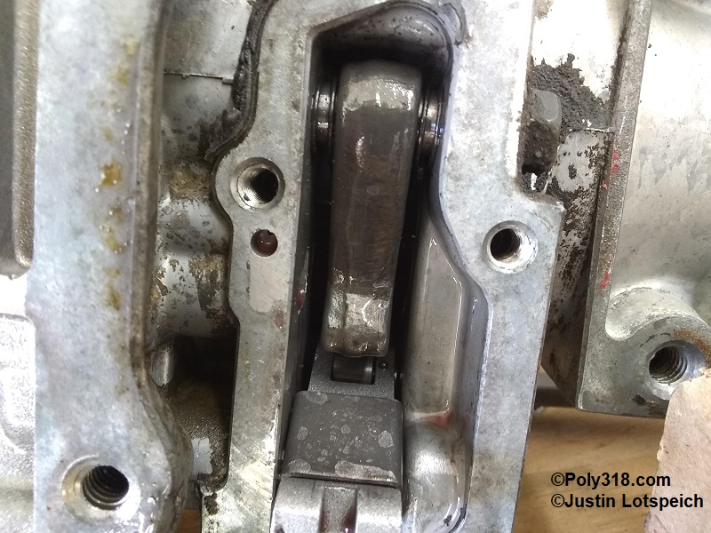
1962 Vehicles that used Lockheed brakes (like Dodge 880 and Imperial) maintained the parking brake drum on the output shaft, while 1962 vehicles that used Bendix brakes (like small Dodge and Plymouth) abandoned the parking brake drum, used a dedicated parking pawl to lock the output shaft inside the transmission via a second cable operated by a parking lever in the cabin, and included a mechanical parking/emergency brake on the rear axle (Figure 4a). From 1963 onward, all A727 abandoned the output-shaft brake drum and used a dedicated parking pawl. The easiest A727 swap into a PowerFlite or A466 car is the 1962 “Lockheed brakes” A727 equipped with the incorporated parking brake, but they are far more difficult to find than a 1962 – 1965 parking-pawl “Bendix brakes” A727. With the 1962 parking-brake A727, you simply connect the car/truck’s parking-brake cable to the parking brake drum.
If you cannot source a 1962 A727 equipped with a parking brake or if you are like me and want the benefit of a dedicated parking feature, the 1962 – 1965 A727 with the parking pawl is the way to go. Two significant considerations are how to address the parking lever and the parking brakes. While I have seen some people simply abandon the parking brake altogether and keep the factory rear axle, I don’t recommend cutting this corner because I want a mechanical parking brake as an emergency brake in the event the hydraulic brakes ever fail and for when parking on a significant grade. In my situation, since I built and installed a high-performance engine, I upgraded the rear axle to a Ford 8.8″ equipped with disc brakes and cable-operated parking brakes and modified a coupler to connect the rear axle parking brake cables to the 1956 Dodge cable. I have a dedicated article on this rear axle swap that addresses the parking brake situation in detail. While I used a Ford 8.8″ for the reasons I explain in the article, any rear axle of the correct width and strength that is equipped with parking brakes can be used, including a Mopar 8.75″, Dana, Ford 8″/8.8″/9″, Chevrolet tri-five/10-bolt/12-bolt, etc.
Addressing the parking pawl gets even trickier since 1955 – 1961 cars/trucks didn’t have the feature on the dashboard. The 1962 – 1965 parking pawl is located on the underside of the tail housing and uses an internal cog fixed to the output shaft. The system is push-pull controlled by a dedicated cable. 1962 – 1965 push-button vehicles had a vertical or horizontal parking lever on the dashboard. One option for 1955 – 1961 retrofits is take a 1962 – 1965 parking lever, fabricate a mounting bracket, and secure the lever to the underside of the dashboard as a horizontal lever. For a greater customized look, you can cut a slot in the dashboard with the lever knob protruding. Keep in mind that using a factory lever requires a long travel for the lever since they had a long sweep.
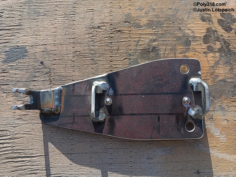
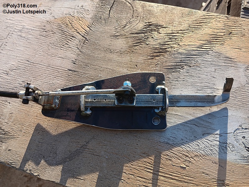
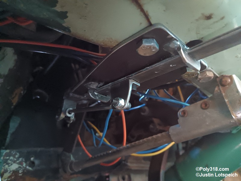
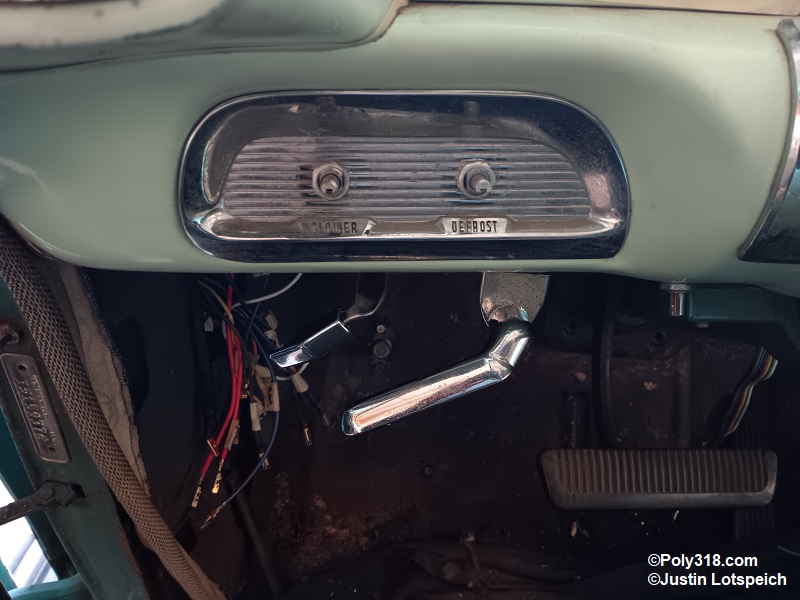
For my 1956 Dodge, I found that the sweep of a factory lever set horizontally under the dashboard was too cramped, so I designed and fabricated my own push-pull lever mechanism. Extremely important, whatever lever you use must have a firm detent to lock the cable in the engaged and disengaged positions. Without the detent, the pawl can vibrate or become accidentally bumped into the engaged position and begin contacting the output shaft cog while driving down the road. If this happens, anything from light damage through grinding to severe damage like a broken pawl or cog teeth can occur. To address the indexing, I used two spring-loaded ball bearings with corresponding chamfered holes in the lever (Figures 4b and 4c). I secured a chromed 1963 Chrysler parking knob to the lever at the same angle that the parking lever vibrated to since the knob has a nice turn for the finger to catch when pulling on the lever. After mocking up the lever in different locations, I settled on the left side of the parking brake handle (Figure 4d and 4e). Pushing the lever engages the parking pawl and pulling disengages it. The indexing detents firmly lock the lever in either of those positions.
Drive Shaft
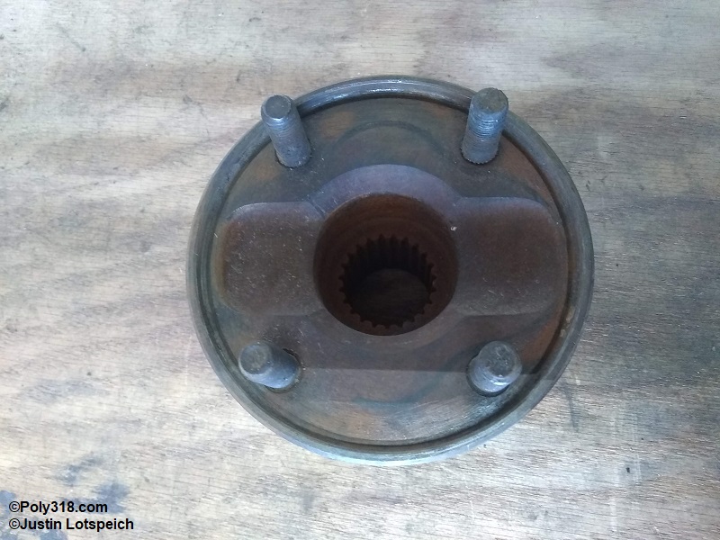
The PowerFlite or TorqueFlite A466 drive shaft cannot be used as a direct bolt-in when changing to an A727. Similar to the PowerFlite and A466 but of different flange design, all 1962 – 1964 A727 used a fixed flange bolted to the output shaft that mates to a ball-and-trunnion driveshaft (Figure 5a). In 1965, Chrysler Corporation began moving to the superior slip-yoke output shaft design, but some 1965 vehicles maintained the fixed flange. While the ball-and-trunnion output shaft is splined to accept the flange, the splines are not remotely similar to the slip-yoke splines and will not accept a slip yoke. A 1965 slip-yoke output shaft and tail housing assembly also can be swapped into a 1962 – 1964 TorqueFlite to convert it to slip yoke if you can located the output shaft and tail housing. However, the 1965 slip-yoke A727 is getting difficult and expensive to find compared to the 1962 – 1964.
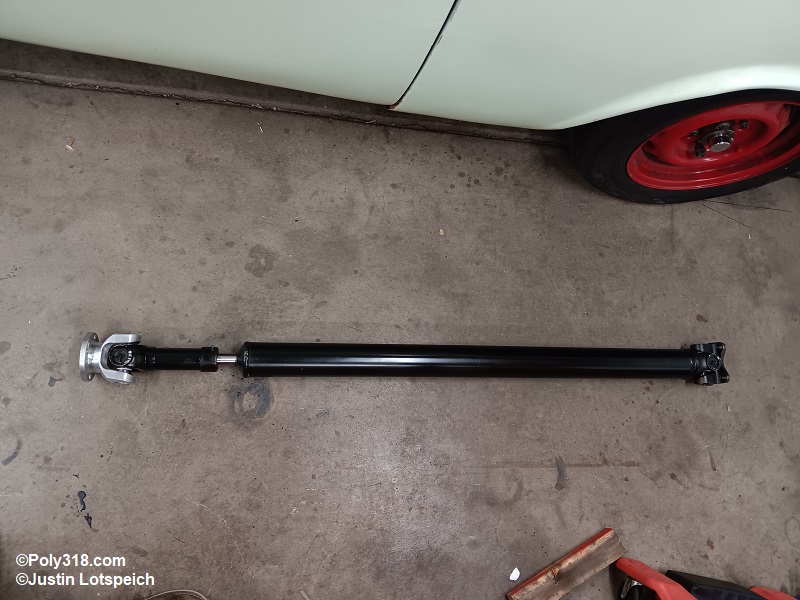
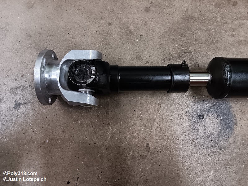
Whichever A727 is used, a new drive shaft will need to be made or the factory drive shaft modified to mate to the A727. A competent driveline shop will have no problem building a drive shaft to mate any rear end to the 1965 slip-yoke A727; however, the shop may have difficulty sourcing components to build a ball-and-trunnion drive shaft for the 1962 – 1964 A727 since many of those parts (flanges and ball/trunnion joint) have gone out of production. Since I used a 1964 A727, wanted heavy duty 1350 u-joints, wanted a 3″ drive-shaft tube, and wanted a slip-yoke incorporated, I had a driveline shop build a drive shaft with a custom billet-aluminum front flange (good for 1,200 ft.lbs. torque), with the flange costing only $100 more than an off-the-shelf flange that doesn’t exist for an A727 with 1350 u-joints and a 3″ tube (Figures 5b and 5c). Another option if you don’t require larger u-joints is to build a 2.5″ tube 1310 u-joint drive shaft like I describe in a technical article on building a slip-yoke driveshaft. These parts are available through Spicer and other manufacturers.
