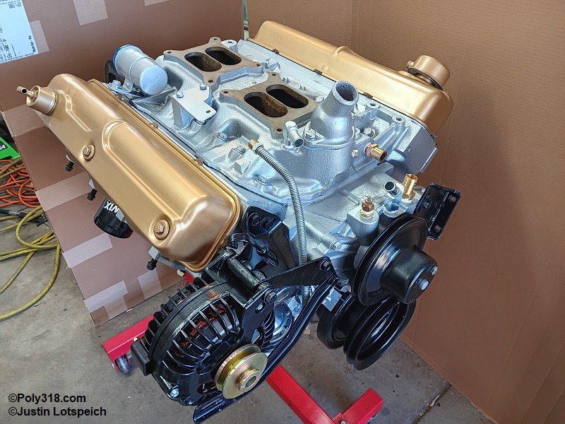
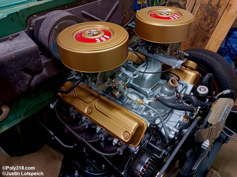
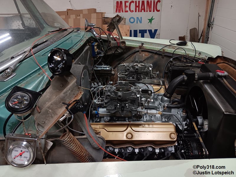
Poly 318 Complete Engine Assembly
(applicable to 277, 301, 303, 313, 318, 326, and 390 and other strokers)
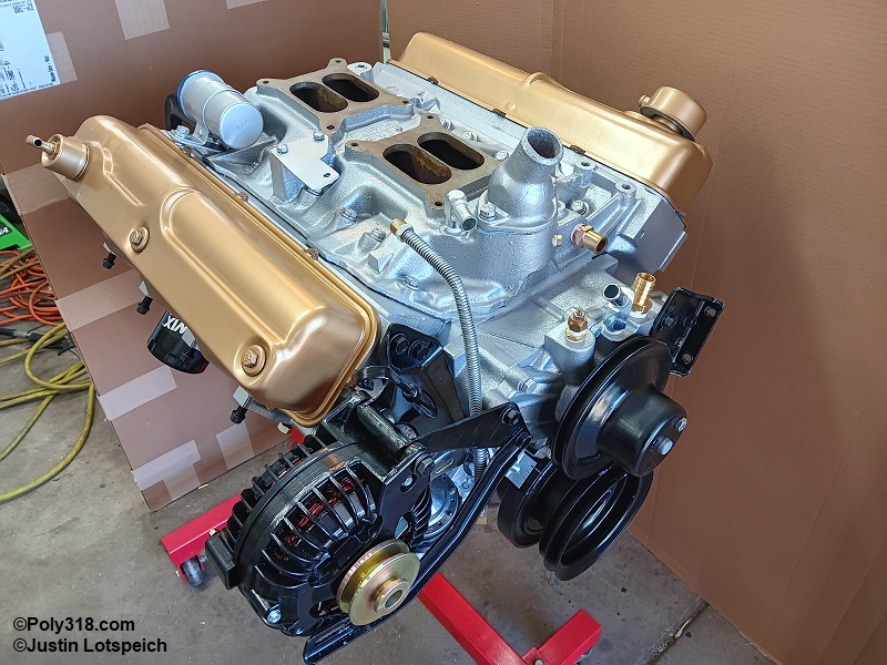
FROM A TIRED FACTORY 318
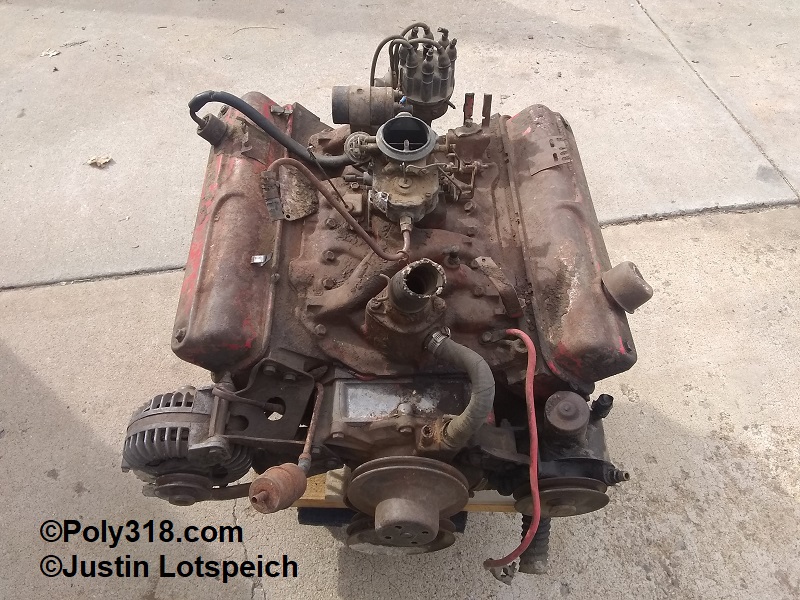
TO A REBUILT 390 STROKER
Introduction
Please note that this page has many photos, so it may load slowly for those with slower internet connections even though I have decreased the image sizes. My first installment of the rebuild series on Plymouth, Chrysler, and Dodge poly A-block engines covers disassembly and machining inspection in preparation for rebuilding. This article goes into extensive detail, step by step, in the entire rebuilding process from cleaning and preparing components to setting ignition timing in preparation for camshaft break-in.
Crucial to a quality rebuild, be careful to keep an extremely clean assembly area and bag/cover the engine and parts whenever not working with them. Separate all machining and preparation procedures far away from the assembly area so you don’t contaminate the assembly process. The assembly area should be clean with the ceiling and any light fixtures above blown off to stop falling debris, workbenches and vises wiped and blown off clean, and the floor swept and blown off clean. Use paper towels, rag, and cardboard when necessary to lay out cleaned parts. Any grit that makes its way between moving parts can cause damage and premature wear.
Materials List
Many of the rebuild parts can be purchased through retailers such as Rock Auto, Summit Racing, Napa Auto Parts, and others. I go into great detail and provide part numbers on the engine parts page. Some parts are interchangeable with LA engines since the LA engineers worked off the A-block platform, which I detail on the parts interchange page. Parts that cannot be purchased new must be machined to tolerance or replaced with a good used part.
- Accessories Brackets
- Camshaft
- Camshaft Bearings
- Cleaning Equipment: Solvents, Brushes, Rags, and Paper Towels
- Connecting Rods
- Connecting Rod Bearings
- Coolant Fittings
- Coolant Thermostat and Housing
- Crankshaft
- Crankshaft Main Bearings
- Cylinder Heads
- Cylinder Head Valves
- Cylinder Head Valve-Stem Seals
- Cylinder Head Valve Springs (and spacers if required for setting seat pressure)
- Cylinder Head Valve Retainers and Keepers
- Dipstick Tube
- Distributor
- Engine Block and Main Caps
- Harmonic Damper with Healthy Rubber
- Intake Manifold
- Intermediate Oil Pump/Distributor Drive Shaft Bushing
- Intermediate Oil Pump/Distributor Drive Shaft
- Fasteners (Bolts, Nuts, Washers, Etc.)
- Flexplate or Flywheel
- Fuel Pump (or block-off plate for electric)
- Fuel Pump Eccentric
- Gasket Set:
- I use FelPro full kit FS7734PT2 and Best Gasket 18019 fiber intake manifold gaskets rather than the FelPro steel intake manifold gaskets included in the kit that are prone to leaking.
- Lifters
- Lubricants
- General Assembly: Red Line 80312
- Camshaft Lobe and Lifter Foot: Driven 00732
- Threads: ARP Ultra-Torque 100-99 series
- Oil
- Oil Filter
- Oil Filter Adapter Plate
- Oil Pan (and windage tray if equipped)
- Oil Pump
- Oil Pump Pickup
- Pistons, Pins, Locks, and Rings
- Plugs: Expansion and Pipe
- Pulleys: Water Pump and Crankshaft
- Push Rods
- Rocker Arms, Adjusters, Spacer Springs, Shafts, and Shaft Locks
- Sealants
- Threads and Plugs Hard Cure: Permatex 80003
- Threads Soft Cure: RectorSeal T Plus 2
- RTV Silicone: Mopar 4883971
- Gasket Maker: Permatex 80019
- Solvents: Lacquer Thinner and/or Brake Cleaner
- Spark Plugs and Wires
- Timing Chain Cover
- Timing Set
- Valve Covers, Breathers, and PCV Valve or Draft Tube
- Water Pump
Camshaft Bearing Installation
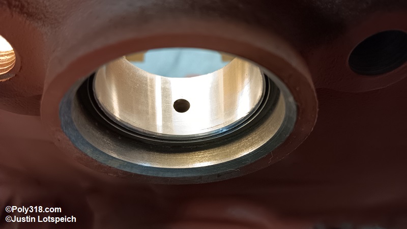
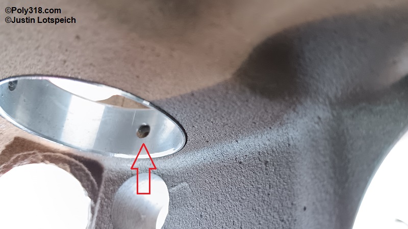
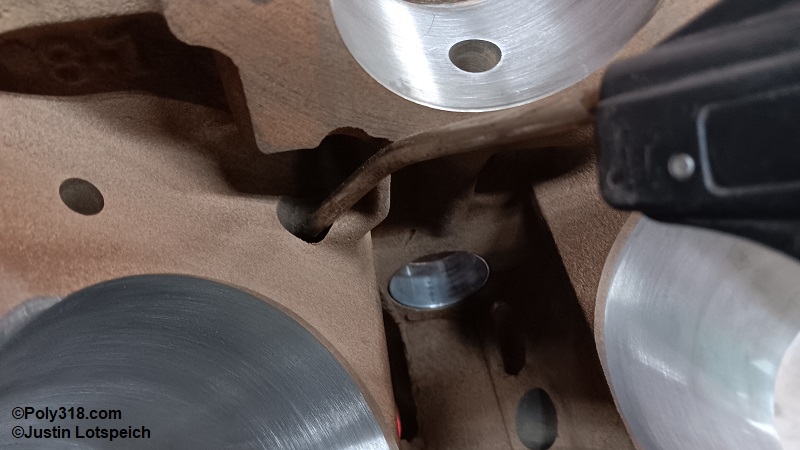
Before I clean the block after machining, I address the camshaft bearings and any stroker clearancing since they may require machining and create metal shavings. With the bare block on a workbench, start the #1 (front) camshaft bearing on the appropriate driver, align the bearing oil hole exactly with the block gallery, and start the bearing square in the bore. Slowly drive the bearing square until it is centered in the bore (Figure 1a). Install the alignment tool in the #1 bearing, slide the driver through the alignment tool and bores, and install the #5 (rear) bearing in the same fashion (Figure 1b). Work forward with the remaining bearings ensuring all oil hole including the double-hole bearings are aligned (Figure 1c). Warning: Aligning the oil holes is crucial since partially or fully blocked holes will starve the camshaft journal and, depending on which bearing, the rocker-arm assemblies of lubrication.
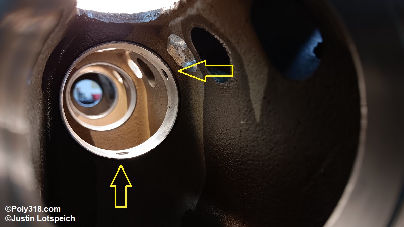
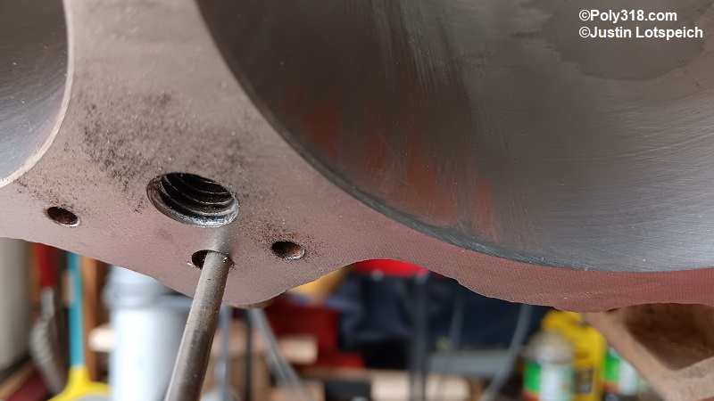
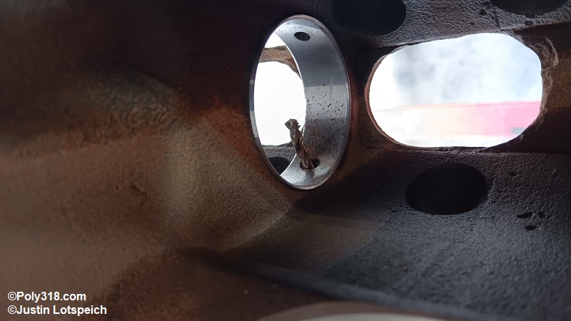
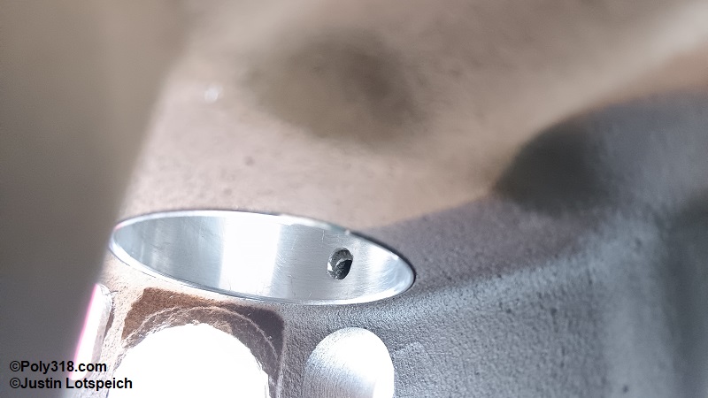
When finished, inspect the oil holes because some block galleries may be drilled off center to where only part of the passage is clear depending on core shift and factory machining tolerances (Figure 1d). For ideal oiling, run a long drill bit through the oil gallery from the main journal or cylinder head deck and drill out the bearing (Figures 1e, 1f, and 1g). Inspect all bearings for burrs and remove as necessary. Blow out any shavings from the block webbing and through the oil galleries with compressed air.
Stroker Crankshaft Clearancing (4” Stroke)
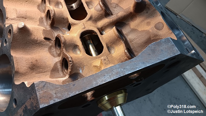
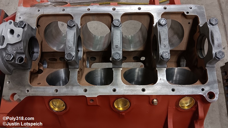
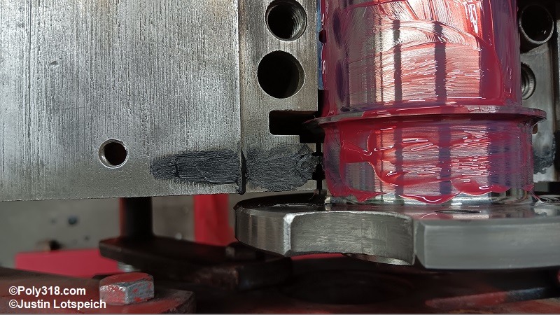
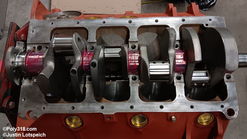
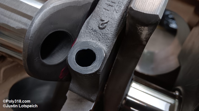
If using a 4” stroker crankshaft, connecting rod and crankshaft clearance with the block must be checked and possibly adjusted. Install new bearings into the #1 and #5 main block and caps, and wipe them clean with lacquer thinner. Coat the bearings in a quality assembly lubricant (I use Red Line R0613) (Figure 2a).
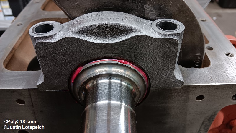
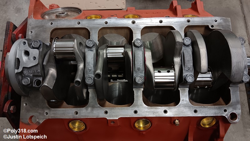
Gently and carefully set the cleaned crankshaft straight down onto the two bearings. Carefully slide the #1 and #5 main caps with bearings installed over the crankshaft with the cast numbers on the left (passenger) side and any cast arrows pointing forward. Tap the caps into place with a rubber mallet. Install clean main-cap bolts dry and tighten back and forth just until they are snug at 120 lb.in. (10 lb.ft.).
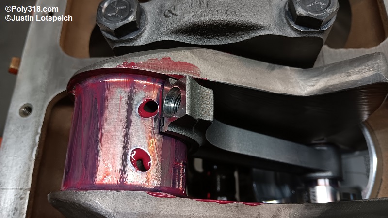
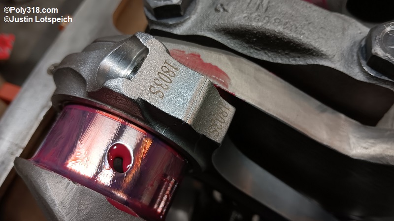
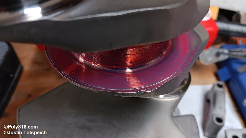
Lightly lubricate a clean wrist pin with assembly lube, slide a clean piston over a clean connecting rod, and slide the wrist pin into place. The pin locks are not necessary at this stage. Install a pair of new, clean bearings in rod and cap and coat them in assembly lube. Warning: Many aftermarket crankshafts have wider fillet radii and require “narrow” bearings to clear the fillet, so ensure the correct bearings are used since wide bearings on wide fillet radii will bind (Figure 2b).
If using cap studs, cover them with protective boots/guides/fuel hose. Carefully guide the rod and piston through the cylinder chamber onto the crank journal being extremely careful not to scratch the cylinder wall or nick the journal (Figure 2c). If using a factory offset rod, ensure the rod is installed with the short offset side facing the other rod. Install the cap and snug the bolts/nuts back and forth to 120 lb.in. (10 lb.ft.) (Figure 2d).
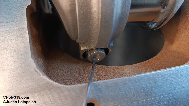
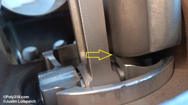
With one hand, hold the rod sideways against the journal fillet, and grasp the crank throws to slowly spin the crank until the rod cap reaches the bottom of the cylinder bore. Use an object that is filed to 0.050” thick (I use steel rebar tie wire) to check clearance between the bolt/nut head and block as you rotate the rod back and forth (Figure 2e). Clearance should be a minimum of 0.050”.
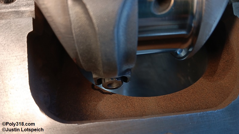
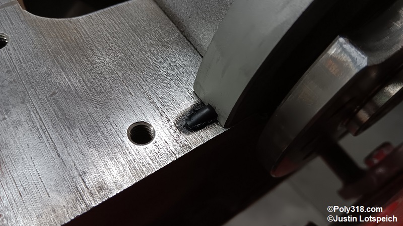
If clearance is tighter than the wire gauge, mark the area(s) requiring clearancing (Figure 2f). Remove the piston-rod assembly, apply a little more lube to the bearings, install the assembly in the opposite cylinder bank on the same journal, and repeat the process for all cylinders even if the rod bolts clear in one or multiple cylinders. Remove the piston-rod assembly and bag the parts for later.
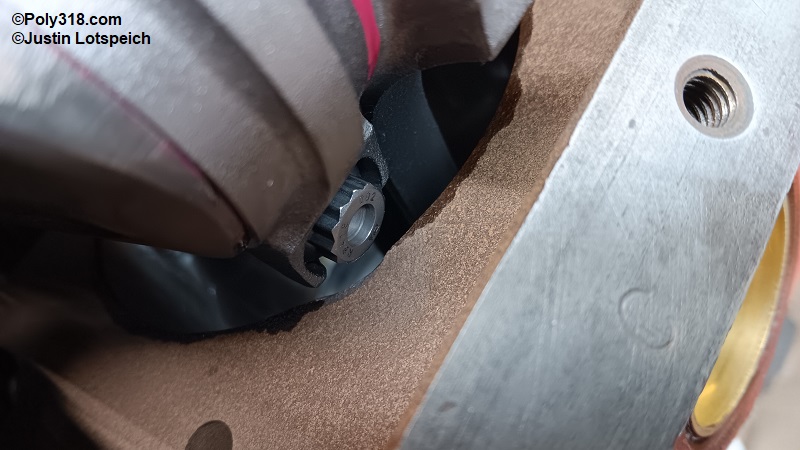
Slowly spin the crank while inspecting each counterweight for clearance between the block. If you find a tight area, which is unlikely, use the 0.050” gauge to check and mark the block for clearancing as necessary. While rotating the crank, look for any other obstructions, such as between the crank throws and pistons that will be tight but should have at least .050” clearance like my engine has (Figure 2g). Remove and bag the crankshaft and bearings for later.
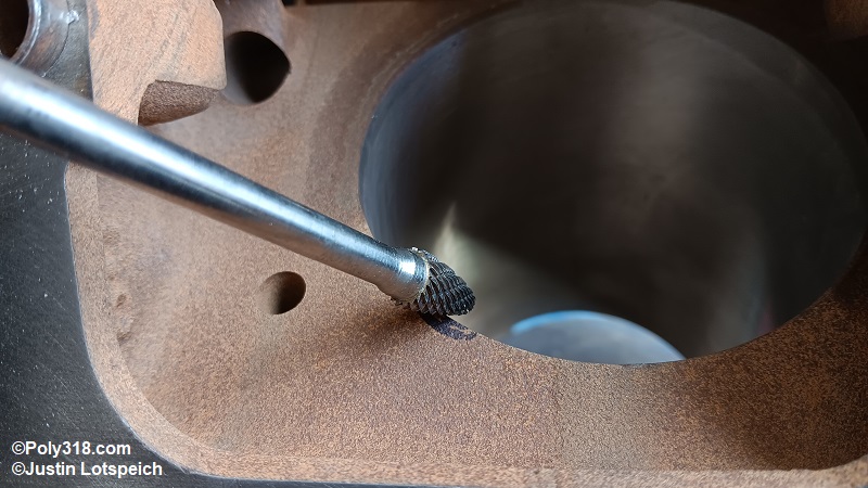
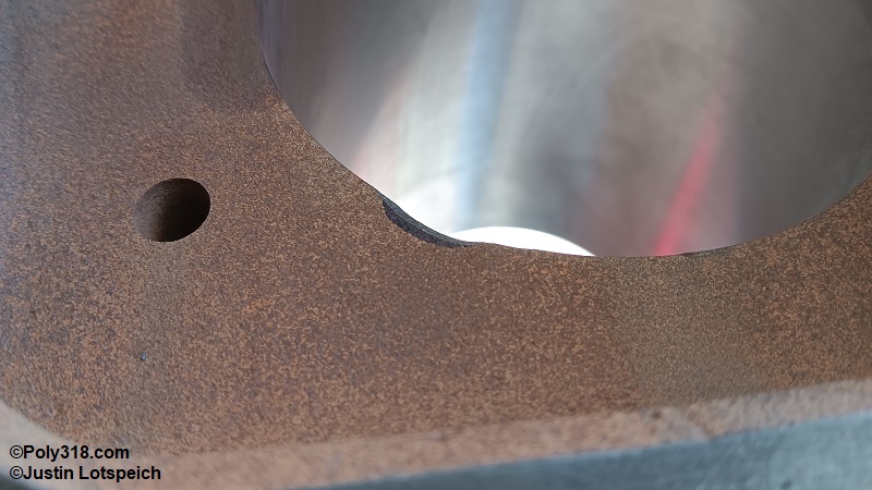
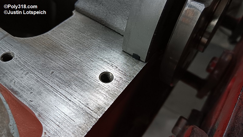
If the block requires clearancing, move to an area far away from the assembly area. Use a die grinder and carbide burr to carefully remove material to the marked line and very lightly ease any sharp edges (Figures 2h and 2i ). Warning: The water jacket runs in the bottom of the A-block and LA cylinder bores, and removing excessive material can thin the wall to either spring a leak or cause future cracking. The A-block and LA 273/318 has plenty of meat in this area to reach the 0.050” clearance on a 4” stroke without issue, but do not remove more material than necessary.
Thoroughly blow off all metal shavings with compressed air. If you are not certain that your marks were accurate, wipe out the cylinders with dry paper towels to remove any shavings, mock up the crankshaft and piston-rod assembly as before, and recheck clearance (Figure 2j). When finished wipe the bearings, journals, and piston pin clean and bag them for later.


Block Preparation and Cleaning
Install the engine block on a stand. If not already done during machining, insert a three-prong wheel cylinder hone into the lifter bores, lubricate the stones and bore with WD-40, and using a variable speed hand drill at low RPM hone the bores just enough to clean the surfaces (Figure 3a). Warning: Over-honing the bore over tolerance will result in premature lifter wear and lower oil pressure.
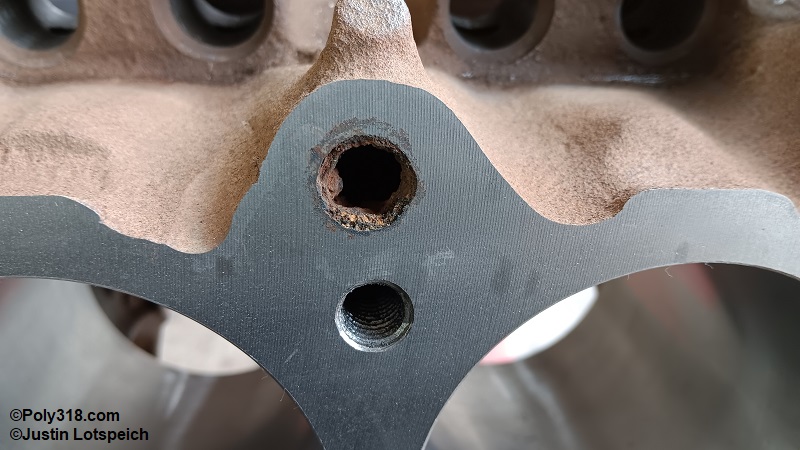
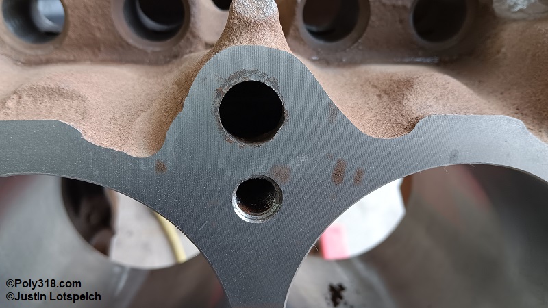
Clean all the threaded bosses using thread chasers in a cordless drill with the clutch set low to where the bit does not break when bottoming out (Figure 3b).
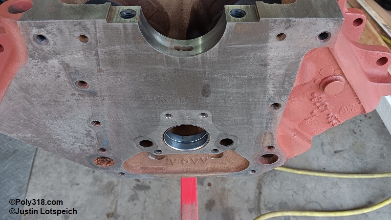
Inspect the rear main seal area and use a pick or small screwdriver to clean out any old rubber and sealant (Figure 3c).
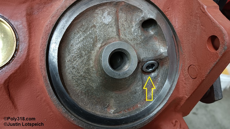
Inspect the water jackets at all openings including pipe and expansion plugs, and use screwdrivers, picks, and/or files to remove any rust obstructions. Check the camshaft plug well at the back of the block and clean out any debris.
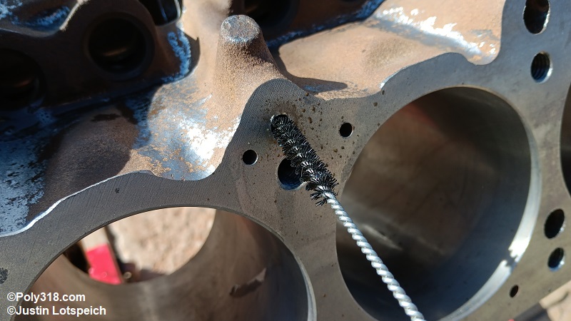
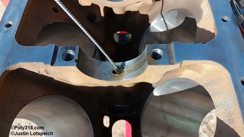
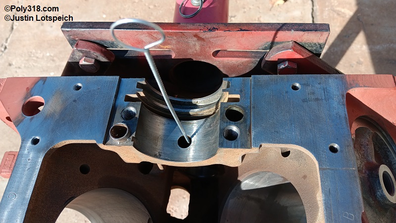
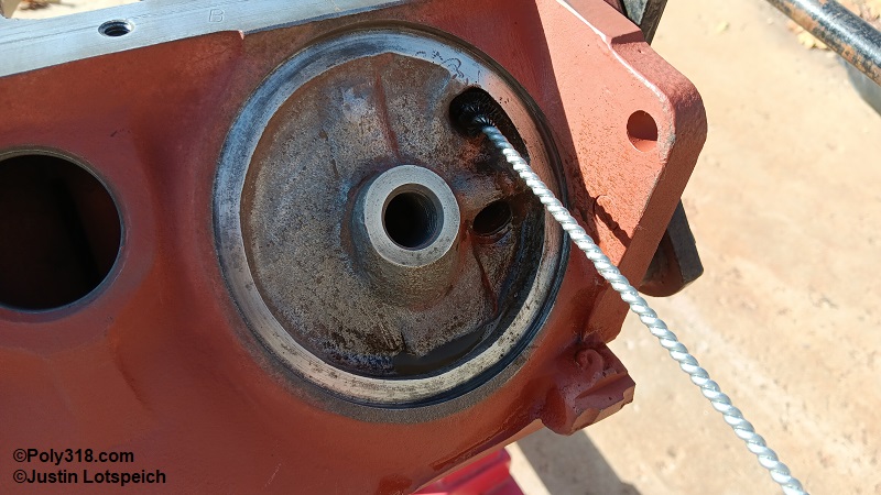
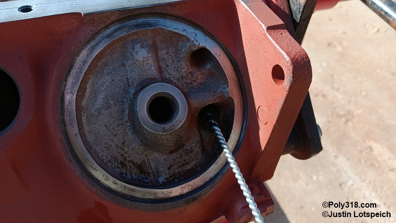
Use a drill bit to clean out any plugged holes at the block deck but do not enlarge the holes (Figures 3d, 3e, 3f, 3g).
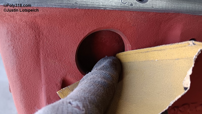
Using 80-grit sandpaper, sand the inside of the expansion plug holes to clean off and scuff the surface for proper sealing (Figure 3h).
Rotate the block on the stand multiple times listening for any chunks of rust or old expansion plugs in the water jackets and remove as necessary. With the block upside down, use a thin compressed air nozzle to thoroughly blow out the jackets up through the deck, water pump outlets, and expansion plug holes. Rotate the block upright and repeat the process until as much rust debris has blown/fallen out as possible.
Inspect all the gasket surfaces, and remove any residual gasket material using a sharp razor blade scraper, wire brush, and/or abrasive pads by hand (Figure 3i). If using an abrasive pad on an angle grinder, be sure to use a medium-grit pad with a very light touch and do not hold the pad in the same spot for too long since it can remove iron and create an uneven surface. Discoloration in the metal is acceptable, but the metal should be free of raised debris.
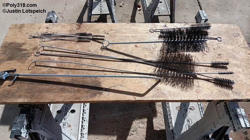
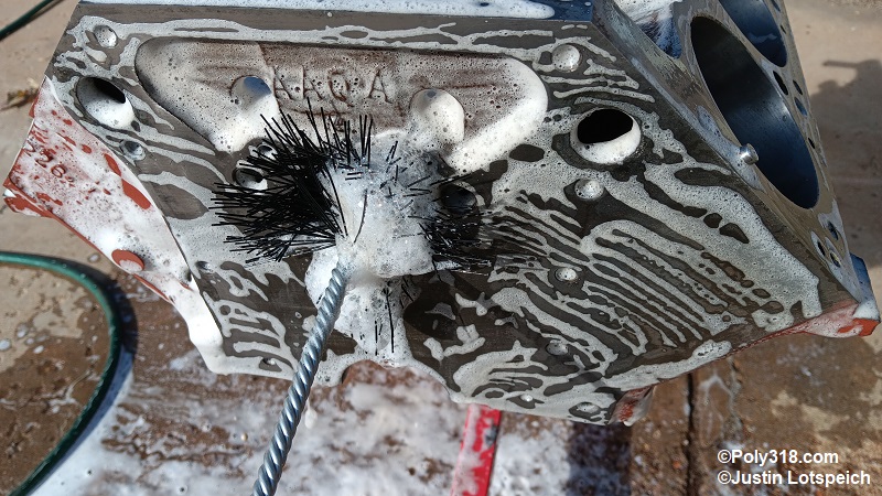
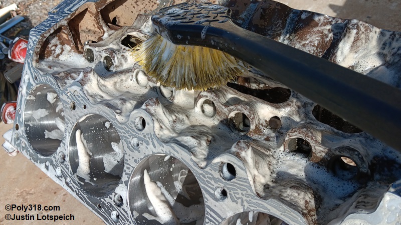
Mix a strong solution of hot water and Dawn original dish soap in a clean bucket. Lay out a selection of industrial-strength nylon rifle and scrub brushes (Figure 3j).
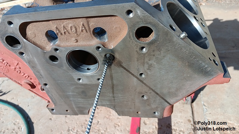
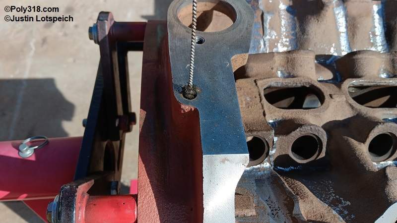
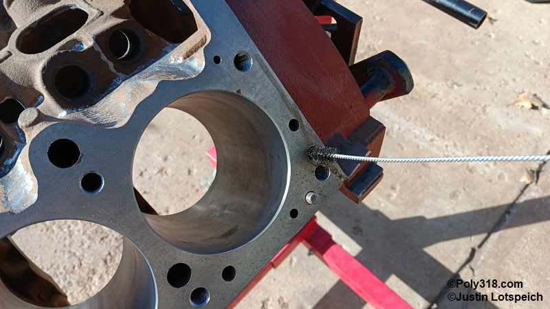
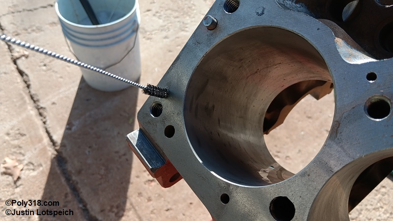
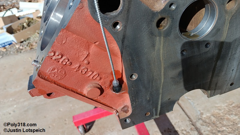
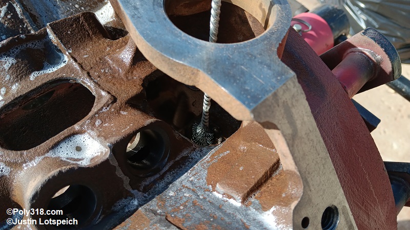
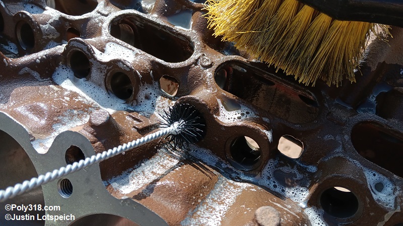
Use long, stiff nylon riffle brushes to scrub out all the oil galleries including the rear main web, oil filter, lifter galleries, main and camshaft webbing, oil drain-back holes for the cylinder heads, dipstick hole, and distributor bushing hole. Brush out the camshaft bearings. Clean the brushes in the soapy solution and keep scrubbing until no debris comes out on the bristles (Figures 3k through 3v).
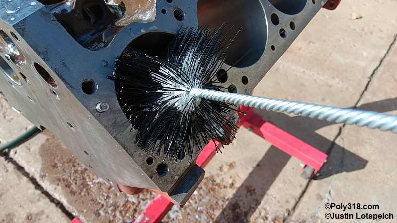
Use large brushes to scrub the lifter and cylinder bores, which will take attention to remove the honing debris (Figure 3w and 3x). Warning: It is crucial to continually wet all the cylinder and lifter bores as you scrub and later as you rinse since allowing them to dry out will cause flash rust that can harm the ring seating.
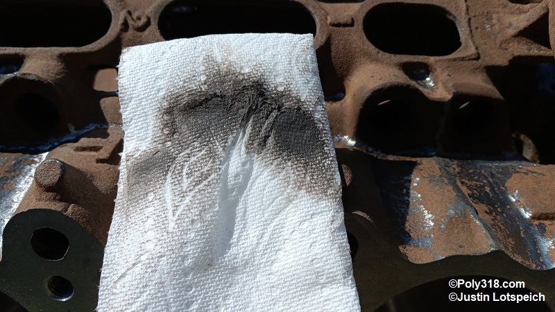
Quickly dry one cylinders with a clean cotton rag. With a gloved hand, soak a clean paper towel or rag with lacquer thinner, and scrub out each cylinder bore well. Even though we already scrubbed the cylinders with the brush, the rag will quickly become dirty with honing debris. Figure 3y shows a paper towel after scrubbing just one cylinder. Continue wiping the cylinder with new towels and lacquer thinner until the towels come out clean. Warning: Don’t use any abrasive scrubbing pads on the cylinder walls since they will knock down the honing ridges and negatively impact ring seating.
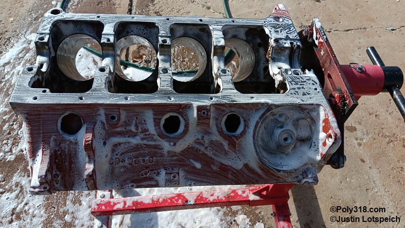
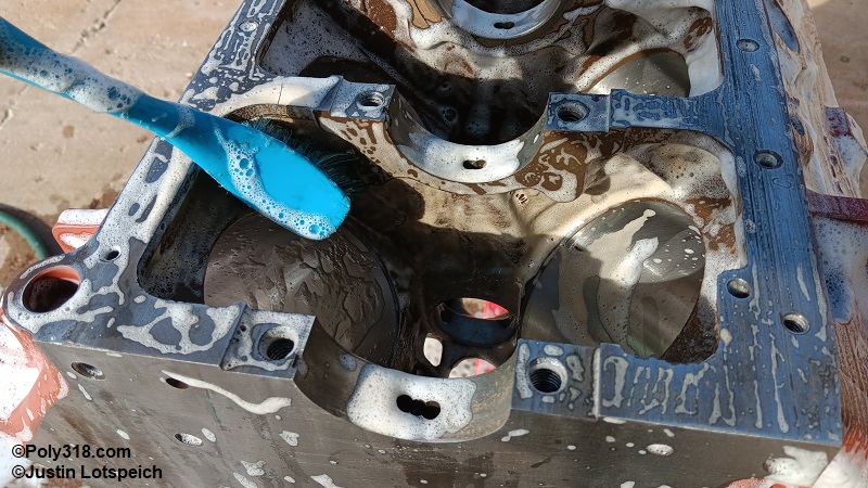
Scrub the entire interior and exterior of the block to remove all debris and oil. Inspect all the inside corners and nooks in the crankcase and lifter valley that collect grime, and use a mechanic’s pick and screwdriver to dig out debris (Figures 3z.1 – 3z.3).
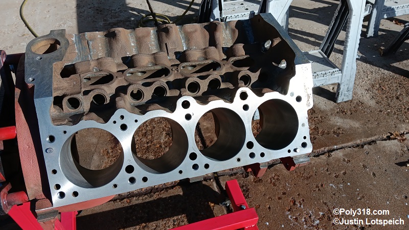
Once the block is thoroughly cleaned, use a power washer or a powerful stream from a hose to thoroughly blast off the block. Shoot water through all oil galleries, water jackets, lifter and cylinder bores, and threaded bosses. Blast water through the deck and pump water jackets allowing the rusty water to run out of the expansion and drain-plug holes. Turn the block upside down and blast water through the expansion/drain-plug holes, and repeat this process rotating the engine until the water runs clear. Once the block is clean, very quickly blow the cylinder bores, lifter bores, and deck dry with compressed air. Some light flash rust may form, which will be addressed in a future step. Blow the rest of the block dry, and allow the block to rest in the sun to heat up and evaporate water inside the jackets (Figure 3z.4).
After the block is dry, blow it off one more time to remove any dust that may have collected while it sat outside. With a gloved hand, wet a clean lint-free cotton rag with lacquer thinner and gently wipe out a cylinder bore. The rag should come out of each bore completely clean. If it is discolored, the cylinder is still dirty with honing residue and should be scrubbed out with a clean cotton rag and lacquer thinner until it is clean. Blow out any lint from all cylinders, wet a clean lint-free cotton rag with WD-40, and gently wipe the bores to protect them from flash rust during the assembly process. Bag the engine block until assembly.

Cylinder Head Preparation and Cleaning
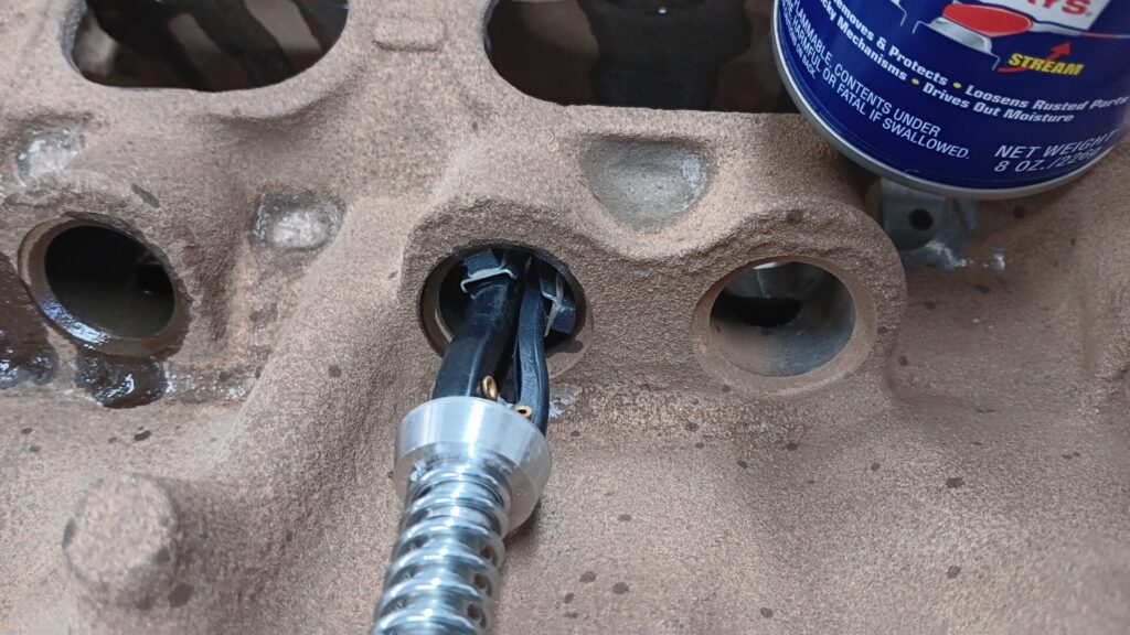
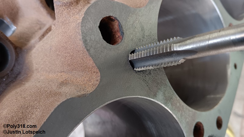
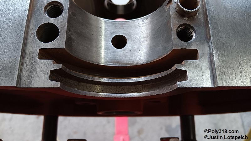
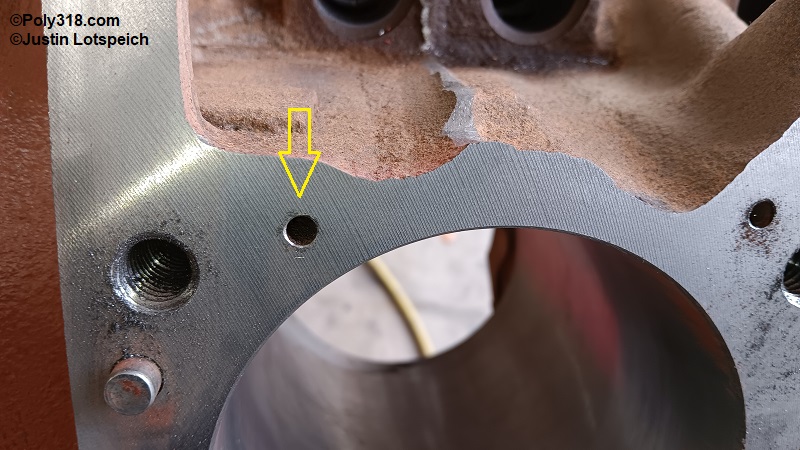
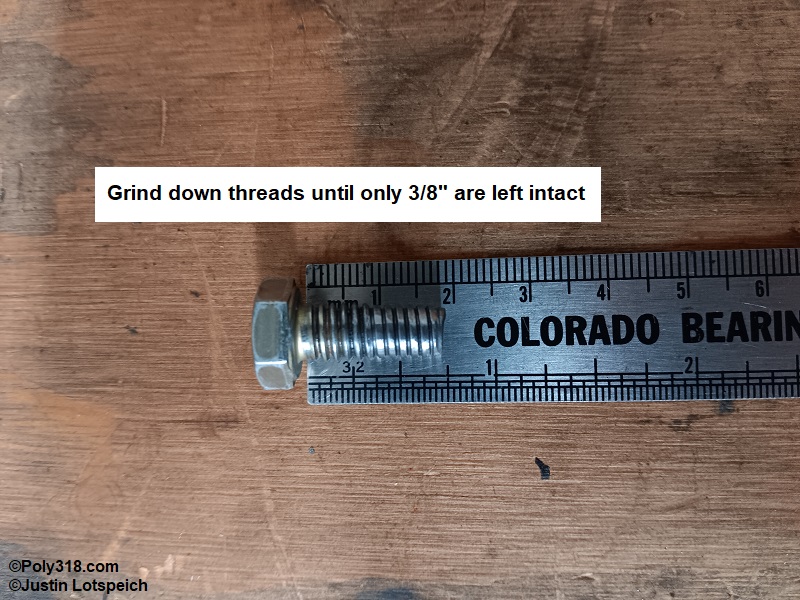
Turning to the disassembled cylinder heads, I highly recommend modifying the rocker shaft locking pin to not reuse the press-pin style. Drill out the pin hole to 17/64” and tap it to 5/16”-18 (Figure 4a). Modify a 5/16”-18 x 3/4″ Grade 8 bolt to grind off the last 3/8″ of threads to allow for oil to pass through the head oil gallery into the rocker shaft (Figure 4b). Warning: Failing to decrease the bolt diameter will block oil flow to the rocker arms. Follow the same cleaning process as the block on both heads. Quickly blow the chambers, seats, and runners dry to stop flash rust before drying the remainder of the head. Bag the heads until assembly.
For more details about cleaning the cylinder heads, rocker arms, and rocker-arm shafts, see my separate article.

Connecting Rod Cleaning, Inspection, and Measuring
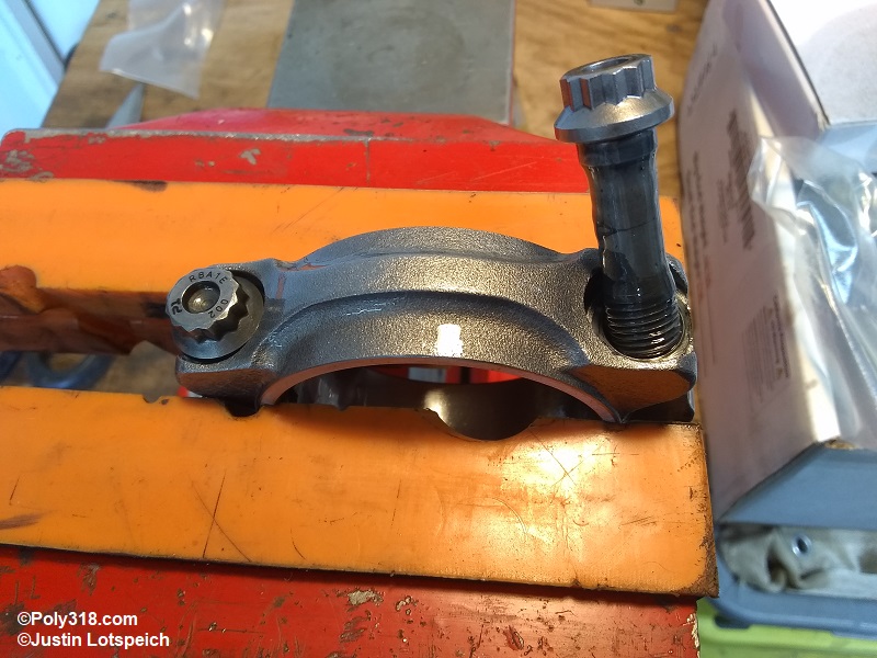
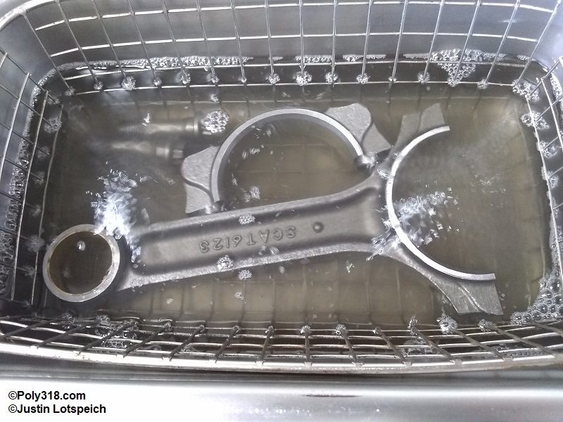
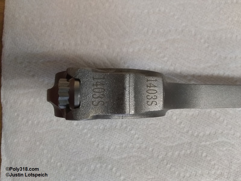
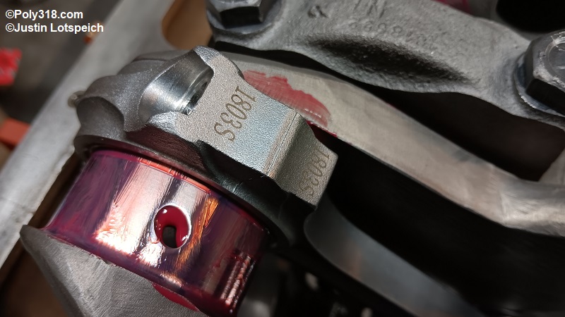
Even if using new connecting rods, do not trust they are clean and ready to install. If equipped, inspect the oiling hole in the pin bore for any burs, and remove them with a file if necessary (Figure 5a). Disassemble one rod in a soft-jaw or rod vise (Figure 5b), and clean the rod, cap, and fasteners in solvent, which I do in a heated untrasonic cleaner at 90° (Figure 5c). Blow the parts dry. Warning: Rods and caps are machined in pairs and must be kept together using the numbers stamped/etched into them, so do not mix them up (Figure 5d).
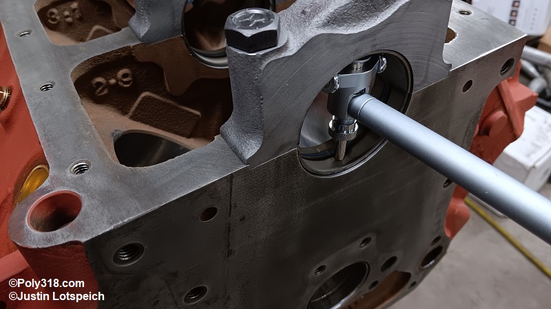
Use a small telescopic micrometer and outside micrometer to measure the piston pin bore and record the diameters for the rod number (Figure 5e). Clean the piston pins and locks in solvent and blow them dry. Using a micrometer, measure the pin diameters, which should be uniform. Subtract the pin diameter from the rod bore to calculate clearance, which should fall between 0.001” – 0.0004” unless otherwise specified by the piston manufacturer.
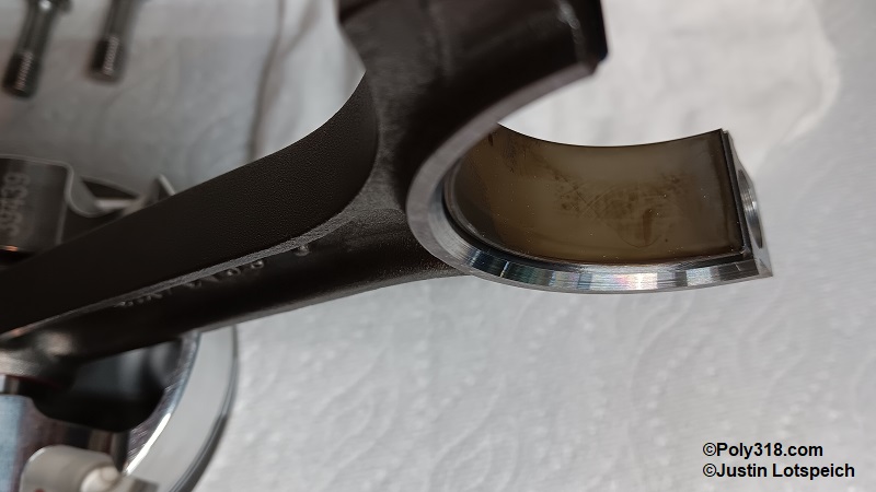
Install clean new bearings in the connecting rods and caps, and push the caps onto the connecting rods. Warning: Many aftermarket crankshafts have wider fillet radii and require “narrow” bearings to clear the fillet, so ensure the correct bearings are used since wide bearings on wide fillet radii will bind (Figure 5f).
Apply a dab of ARP Ultra-torque on the cap around the bolt holes and on the bolt threads and tighten the bolts/nuts finger tight. Place a connecting rod into a soft-jaw bench vise or rod vise. Moving back and forth between the two bolts, tighten them in three steps to their specification. For the 7/16” ARP bolts on this engine, I torqued to 20, then 40, and finally 65 lb.ft. For factory nuts, torque to 15, then 30, and finally 45 lb.ft.
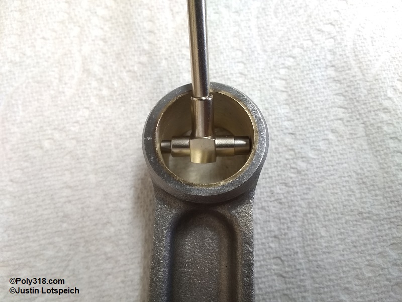
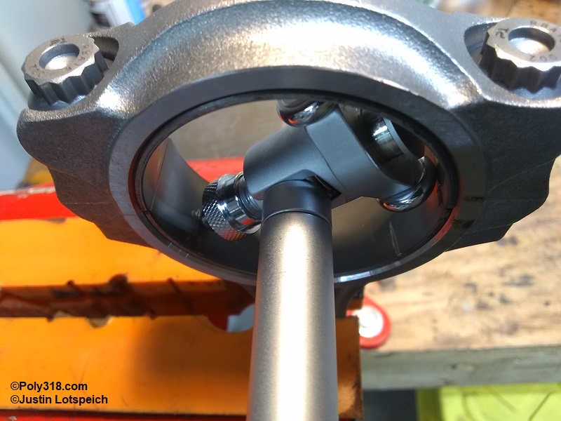
Insert a dial bore gauge to measure each bearing at three different locations of 10:00, 12:00, and 2:00, and record the diameter for the rod number (Figure 5g). The measurement can be taken with a telescoping gauge and micrometer carefully, but the process is less accurate. You will use these diameters soon to calculate bearing clearance. Loosen the rod bolts/nuts but keep them installed, and knock the end of the cap with a rubber mallet to separate the cap, and bag the rods for later use.

Crankshaft Cleaning and Inspection
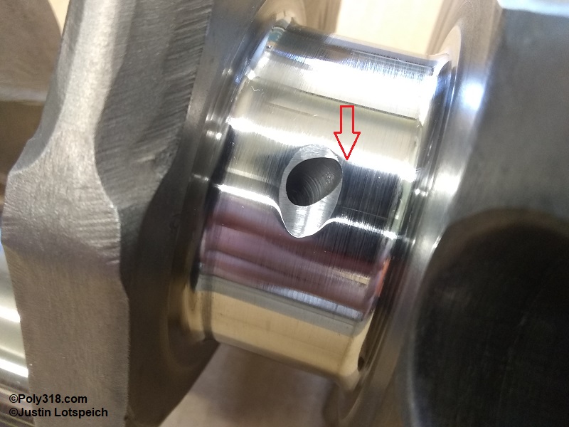
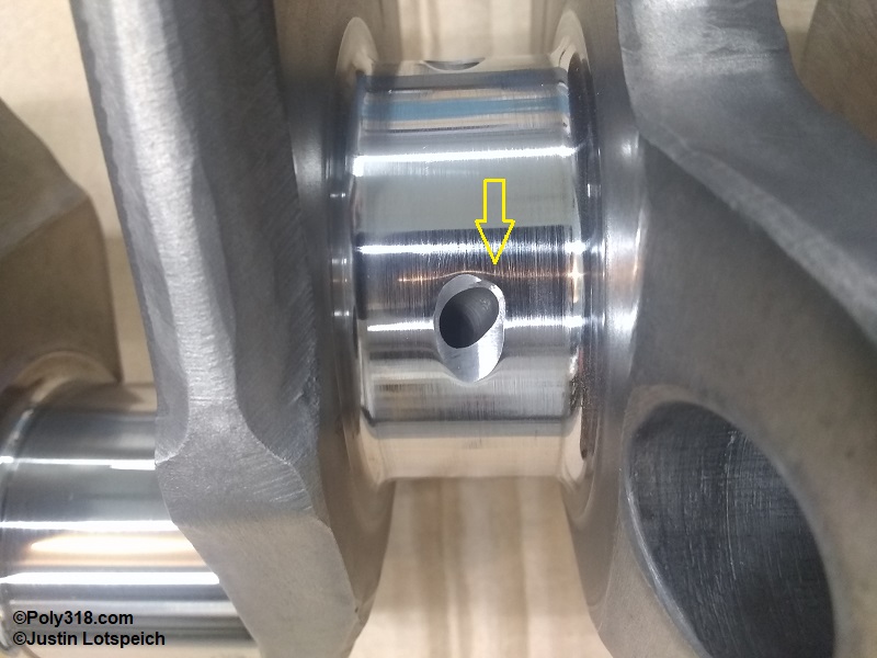
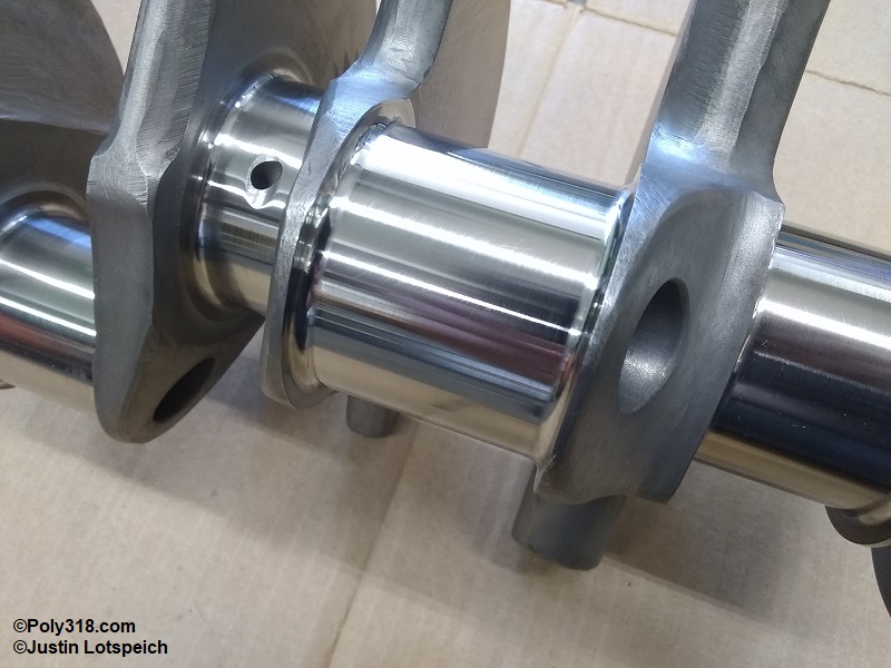
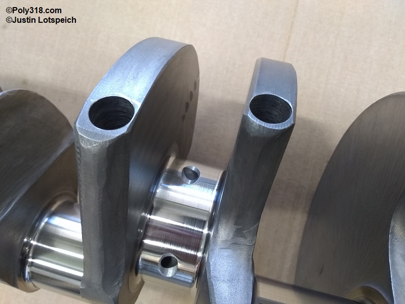
Before cleaning the crankshaft, inspect all the oil gallery openings. They should not have any burrs, and those chamfered should have a chamfer around the entire opening, which some of mine on the new forged stroker crankshaft did not have (Figure 6a). If a section of chamfer is missing or a burr is present, use a die grinder or Dremmel with a tapered stone to gently chamfer or ease the edge being extremely careful not to nick the journal (Figure 6b).
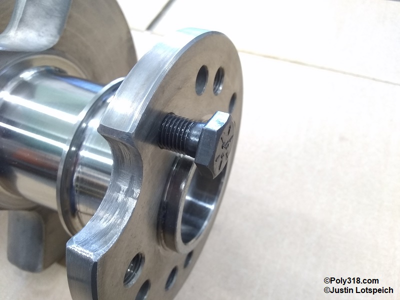
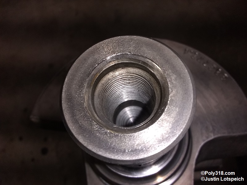
Thread a bolt into all the rear flange holes to ensure the female threads are free of debris and damage (figure 6c).
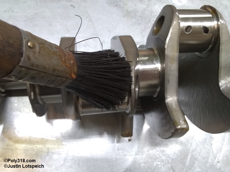
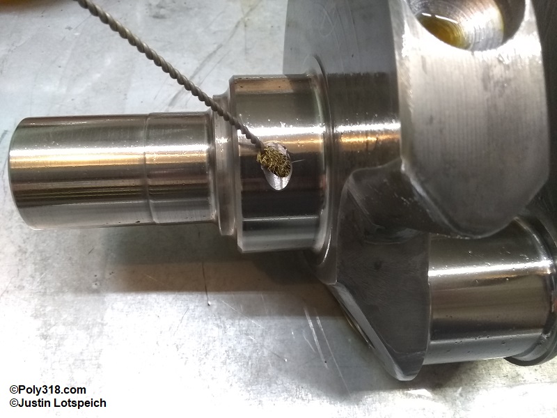
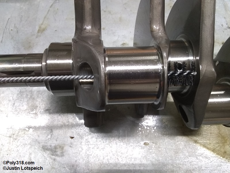
Place the crankshaft in a solvent tank or container, and use nylon scrub brushes and nylon or brass rifle brushes to thoroughly clean the crankshaft (Figure 6d). Scrub all oil galleries, any lightening holes in the rod journals, balancing holes in the throws, rear flange threaded bosses, and front threaded boss (Figures 6e, 6f, 6g).
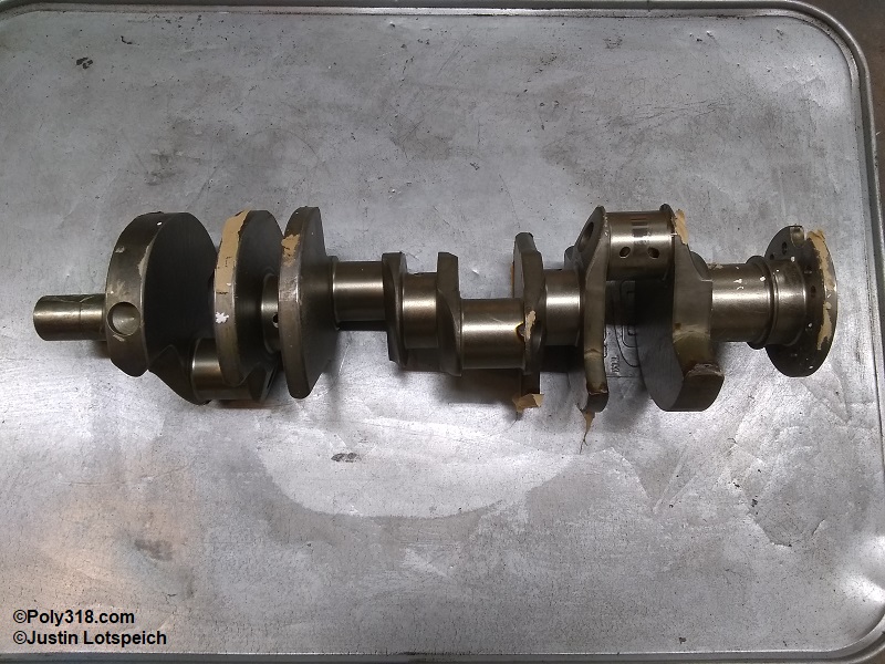
Note for New Crankshafts: If the crankshaft is coated in a thick corrosion prohibitor, the best chemical I have found to dissolve it is WD-40. Spray the crank thoroughly and allow it to soak for a few hours before scrubbing it (Figure 6h).
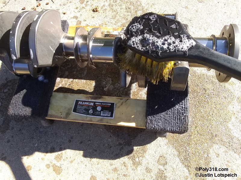
After the crankshaft has been thoroughly scrubbed, mix up a strong solution of hot water and Dawn original dish soap, and scrub the crankshaft including the oil galleries and threaded bosses to remove all solvent and debris (Figure 6i). Rinse it well with clean water, blasting out the oil galleries and threaded bosses with a power washer or strong hose. Quickly dry it with compressed air.
Closely inspect all the main and rod journals for damage. Very superficial scuffs marks from cleaning won’t harm anything, but there shouldn’t be scratches that a pick or fingernail can catch (Figures 6j and 6k).
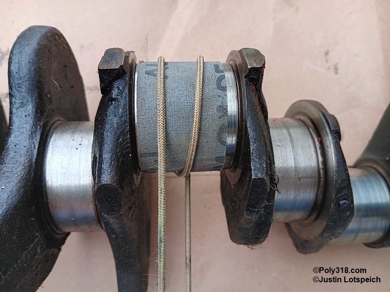
If the crankshaft has either already been turned and polished or it is a used crankshaft within spec but there are any areas that catch on a pick/fingernail, they should be knocked down and polished. Wrap a length of 600-grit emery cloth all the way around the journal to where about 1” of the cloth overlaps itself. Wrap a boot/shoe lace around the emery cloth twice (Figure 6l). After soaking the sanding cloth and journal with WD-40, pull one end of the lace and then the other back and forth to spin the sanding cloth on the journal, and polish the journal moving the sanding cloth back and forth evenly to cover the entire journal until any raised burr is removed. Switch the emery cloth for 1,000-grit crocus cloth to put a final polish on the journal. For light scratches, you can bypass the emery cloth and use the crocus cloth only. The goal in this case is to remove any ridge and polish the journal and not necessarily to remove the entire valley of the scratch since that is work that should be done by a machinist on a crank lathe. A scratch valley will not damage a bearing, but a raised ridge/burr will. Clean the crank again in soapy solution to remove all oil and sanding grit.
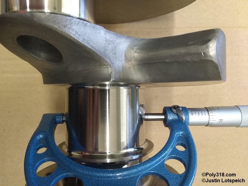
Using a micrometer, measure and record the main journals with the forward journal noted as #1. Measure at three different clock positions to check for out-of-round and taper, which should fall below 0.001”. If there is more than 0.001”, the crankshaft requires grinding. You will use the diameter measurements to calculate bearing clearance later (Figure 6m).
Using a micrometer, measure and record the rod journals where each connecting rod rides with the forward journal as #1. Measure at three different clock positions to check for out-of-round and taper, which should fall below 0.001” (Figure 6n). If there is more than 0.001”, the crankshaft requires grinding. Subtract the rod-journal diameter from the corresponding rod journal measurements you took earlier with he bearings installed to calculate the rod-bearing clearance that should be 0.0005” – 0.0025.” My engine had 0.0020 across all rods. Performance engine often shoot for 0.002 – 0.0025”. If the clearance is outside this range, over or undersized bearings must be used or the crankshaft machined. When finished measuring, bag the crankshaft for later.
Lifter Cleaning and Inspection
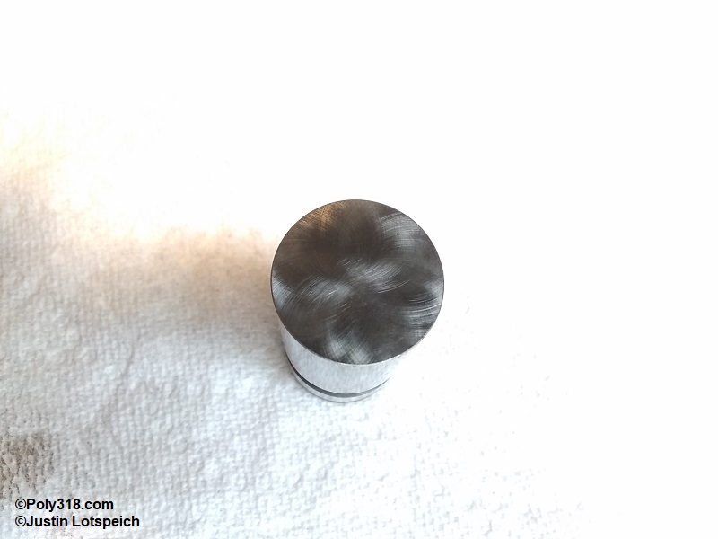
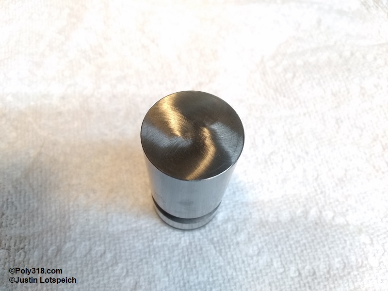
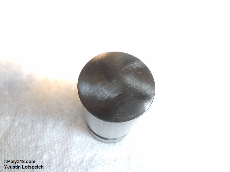
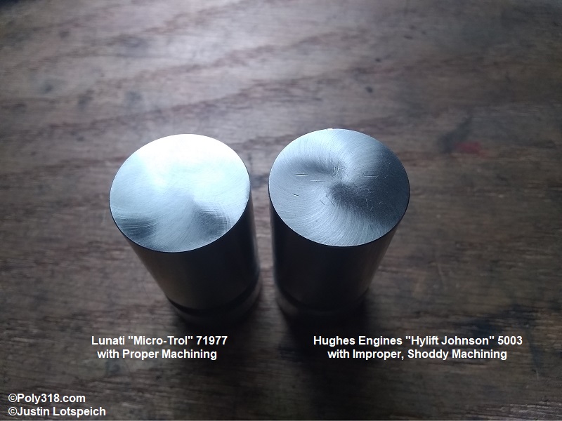
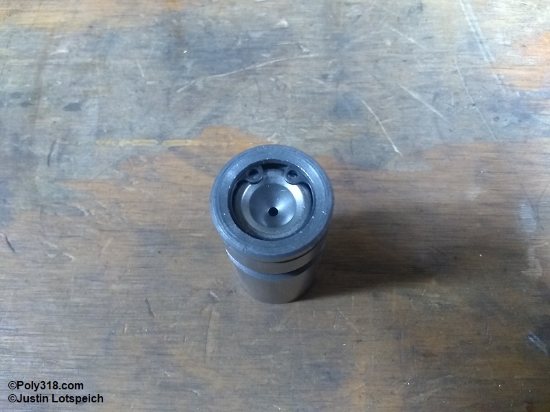
Lifter quality and cleanliness should be a central concern in an engine rebuild. Never trust that lifters are clean from the manufacturer (I have never found a set that are). To begin, look at the foot for a uniform, smooth finish free of gouges and nicks. The machined pattern can vary from a flower, machine-turned, to a swirl, as was the case for the Lunati Micro-Trol 71977 lifters I use (Figures 7a and 7b). Light scuff marks often in ring patterns from sliding along the assembly conveyor equipment are acceptable (Figure 7c), but a mechanic’s pick should not catch when drawn across the foot. There should be a uniform, smooth chamfer on the edge free of nicks and raised material. Any raised material on the edge chamfer may be smoothed with 600-grit emery cloth wet with WD-40, but the sanding should be even around the entire perimeter to not sand in a flat spot. Warning: Do not sand the foot surface since the foot has a delicate crown machined in.
If the lifter foot has nicks, gouges, or other damage like the 16 Hughes Engines “Hylift Johnson 5003” I received shown in Figure 7d, discard the lifter since these blemishes can result in the lifter catching on the camshaft lobe, stopping spinning, and causing the lobe and lifter to flatten. The blemishes are a the hallmark of shoddy craftsmanship and parts handling by the manufacturer and supplier.
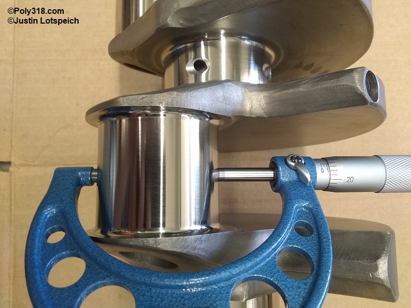
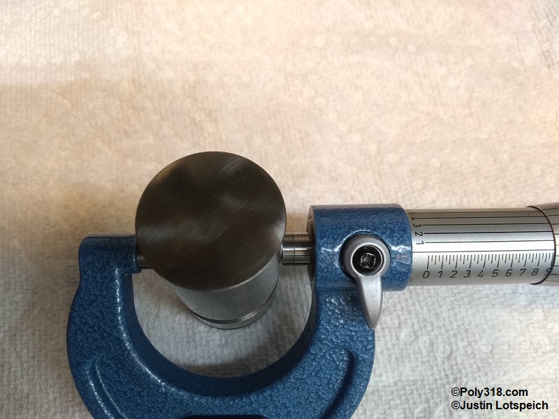
Use a micrometer to measure the diameter at the top, center, and bottom of the body, which should all match to show an evenly round lifter (Figure 7e). Compare the measurement to the engine manual specification to ensure they are within tolerance. All sixteen of my Lunati lifters measured 0.9040″ within tolerance of 0.9040″ – 0.9045″. Lifters that fall outside tolerance should be discarded.
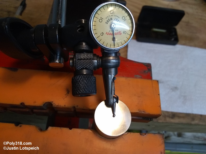
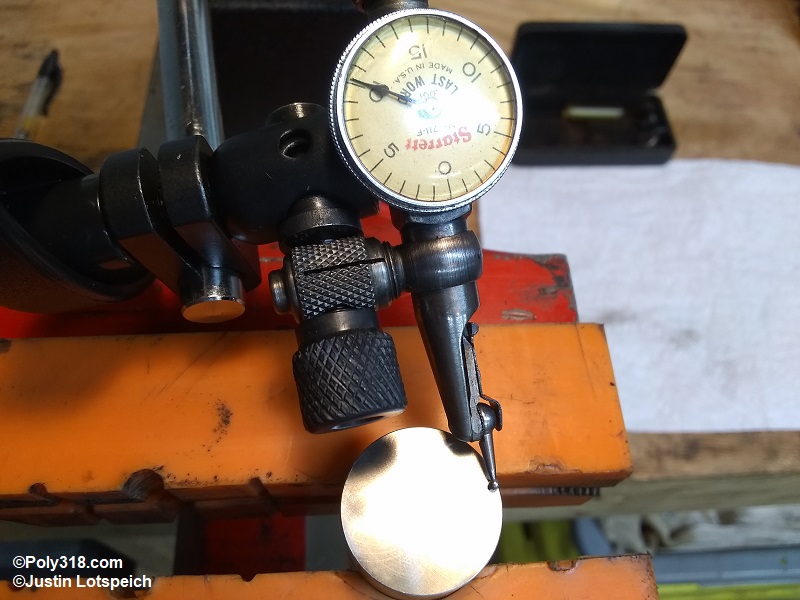
The next step checks the crown of the foot. Most A-block and LA flat-tappet lifters want between 0.002″ – 0.003″ of crown height compared to the perimeter of the foot. Most camshaft lobes have between 0.0007″ – 0.002″ of taper across the face. The lifter crown and cam lobe taper work together to make the connection just off center of the foot and lobe to constantly spin the lifter. Secure the lifter and set up a dial indicator in the middle of the foot touching the surface, which is the highest point, and zero out the gauge (Figure 7f).
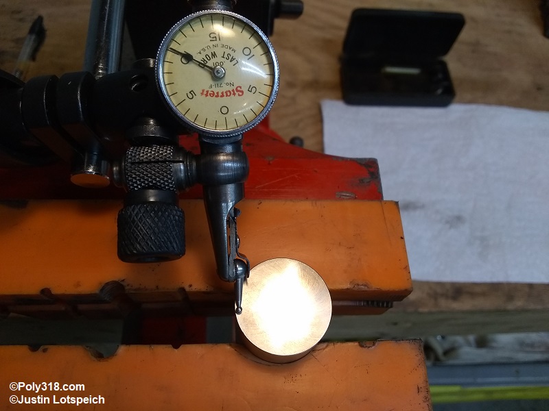
Gently swing the base arm to the side until the indicator rests just before the chamfered edge. Write down the measurement, which is the crown height and in the case of these lifters a hair under 0.0020″ (Figure 7g).
Gently swing the base arm to the opposite side until the indicator rests just before the chamfered edge. Write down the measurement, which in the case of these lifters was a hair under 0.0020″ matching the opposite side (Figure 7h). If the measurements do not match, reset the gauge to zero in the center and recheck the perimeters. If the second measurements don’t match, either have the lifter resurfaced or discard it since the crown is not even and may cause excessive lobe and lifter wear.
When cleaning the lifters, it is crucial to keep all components of the individual lifter together during because the factory uses different sized internal components for each lifter body to maintain specifications to where each lifter’s components are a matched set. Do not simply disassemble all the lifters and throw the parts into the same container.
Secure the lifter in a soft-jaw bench vise. These Lunati lifters use a snap-ring, but other retainers include wire clips and sheet metal inserts. Using snap-ring pliers or a small screwdriver, remove the retainer (Figure 7i).
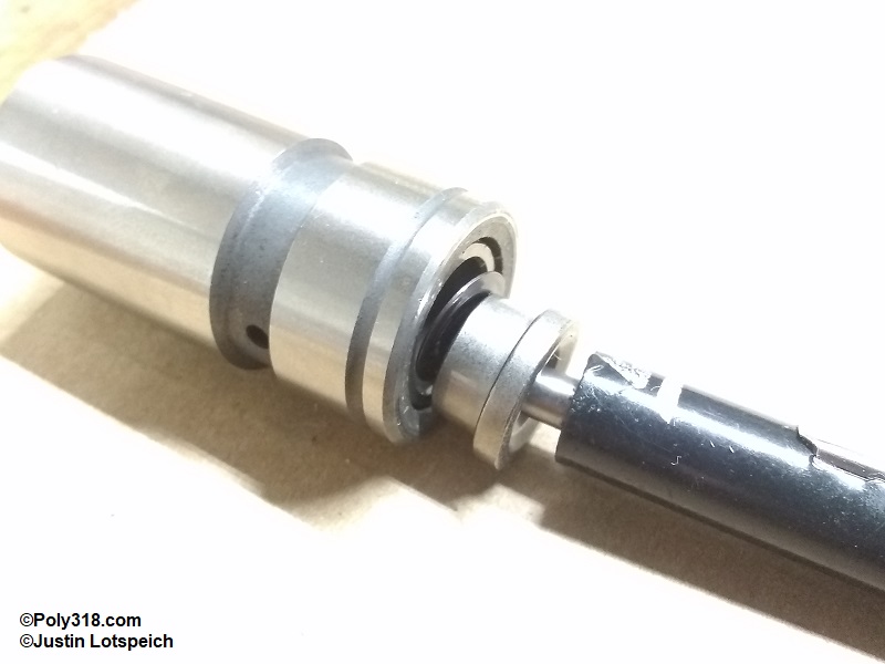
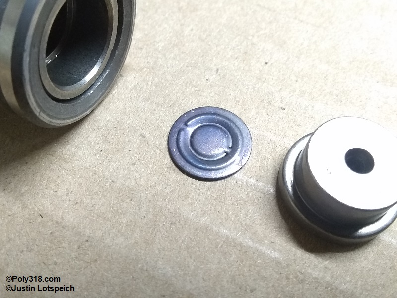
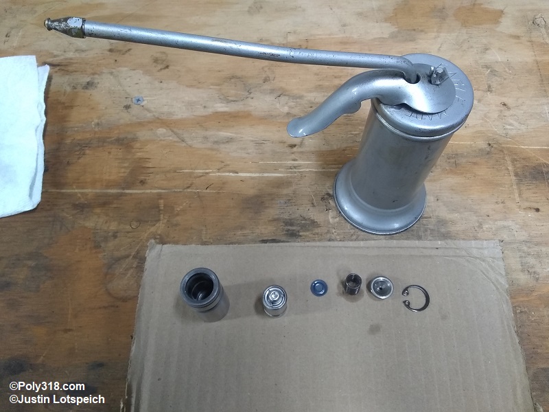
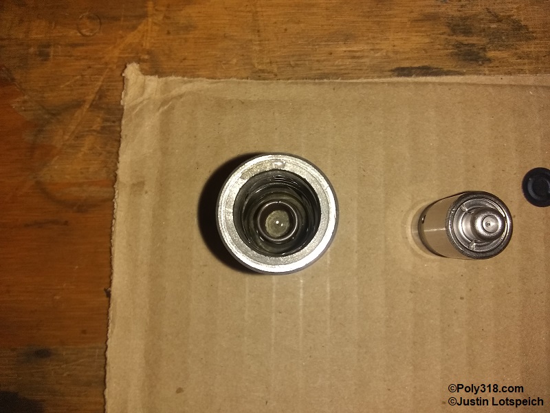
Using a magnet, very slowly lift the plunger cup out of the body until the metering valve is visible (Figure 7j). Before dumping out the contents, stop and inspect the metering valve to see if it has a unique shape that has an “up” side and a “down” side, and take a photo of or draw this part to ensure you assemble it correct-side up (Figure 7k). If the valve flips before the position can be confirmed, plan on carefully checking another lifter during the next disassembly. For these Lunati lifters, the metering valve has a large-diameter bead and a small-diameter bead with ridges on opposite sides of the valve. The ridge of the large-diameter bead faces up, like in the image, toward the plunger cup. While I am not a lifter engineer and do not know if the valve must be placed in this position to function properly, all sixteen valves were in this position and will be reinstalled in the same position.
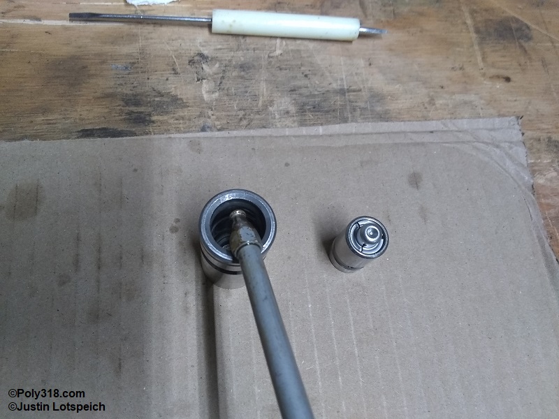
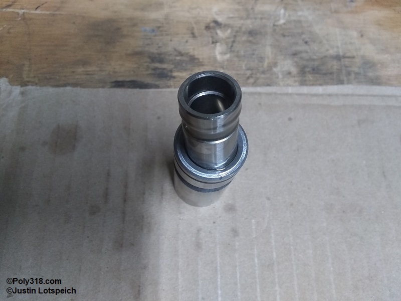
The plunger will often be stuck firmly in the body due to suction and will not drop out when overturned. Sometimes, the plunger will lift out by jambing a finger or rubber-coated plier handle into the plunger and twisting/lifting up. However, I almost always have to use a tool. I slide two short pieces of 1/4″ vacuum hose over snap-ring pliers to protect the plunger’s bore wall, insert the pliers into the bore, tighten the pliers against the wall, and lift out the plunger. Invert the lifter body over a container to pour out the assembly fluid and the plunger spring.
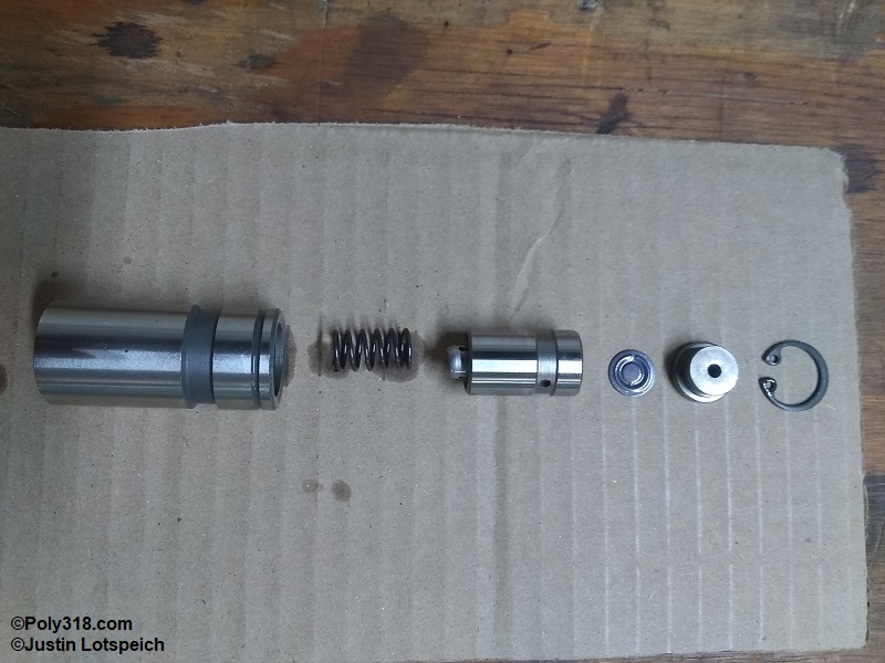
Figure 7l shows the disassembled lifter ready for cleaning including the body, plunger spring, plunger, metering valve, plunger cup, and retainer snap-ring. Warning: These parts must be kept together as a unit for each lifter and should not be mixed up with other lifter components.
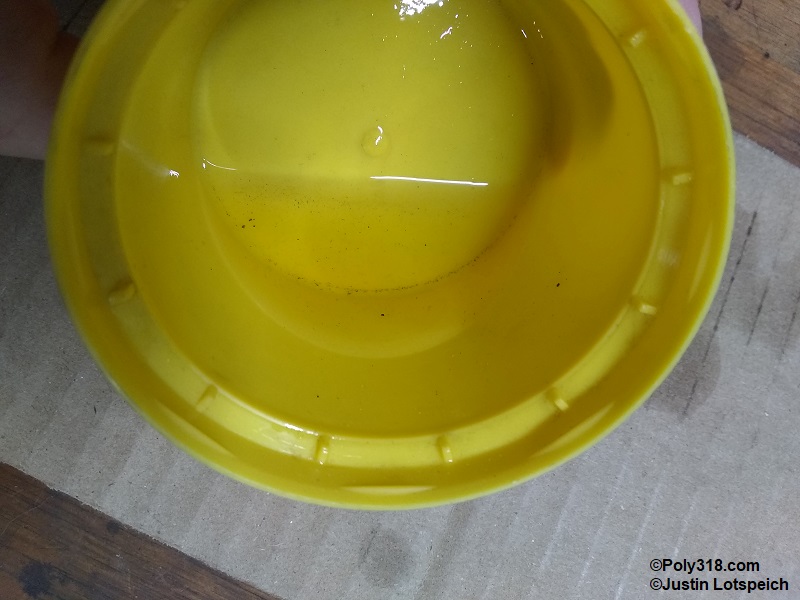
Figure 7m shows a container with all the oil I poured out of the sixteen lifters. Notice all the machining shavings/dust that would have been sent through the engine if I had not taken the time to disassemble and clean the lifters.
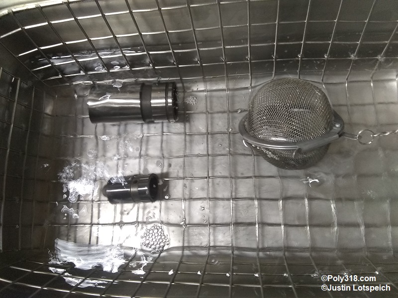
To clean the components, I use a heated ultrasonic cleaner with new mineral spirits at 90°F. This method takes only three minutes per lifter to fully clean the parts. Place one disassembled lifter in the bath at a time (Figure 7n). Place the cleaned parts on a few clean paper towels to drain, and then blow them off well with compressed air, and set the components aside at the clean assembly area.
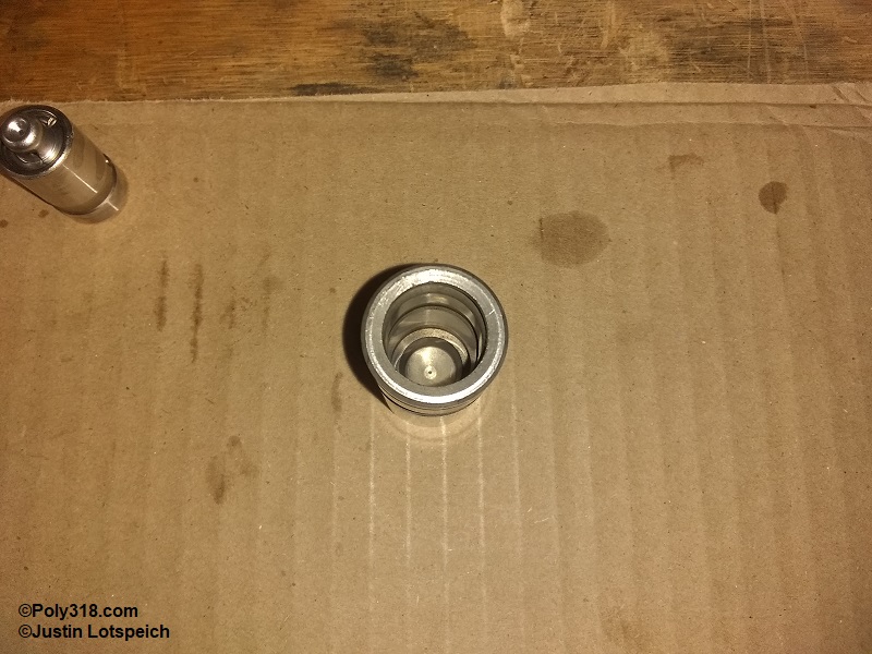
Closely inspect the body bore for any burrs or raised edges that may cause the plunger to hang up. Inspect the plunger exterior for similar (Figure 7o). If any burrs or raised edges exist, knock them down with 600-grit emery cloth wet with WD-40 and clean the part again. These Lunati lifters had no issues.
Lay out the parts in an assembly line, and obtain motor oil or a light oil like 3-in-1 for assembly (Figure 7p).
Place three drops of oil down the side of the body bore. Do not fill the bore full of oil but just enough to lubricate the plunger (Figure 7q).
Drop in the plunger spring and ensure it is centered down in its well and standing straight (Figure 7r).
Place a few drops of assembly oil on the outside of the plunger, gently drop it into the body, and spin it a couple rotations to spread the oil and to ensure the plunger seats on the spring (Figure 7s).
Drop the metering valve into the plunger being careful it is positioned with the correct side up (Figure 7t). Place a single drop of oil on top of the metering valve, and drop the plunger cup atop it.
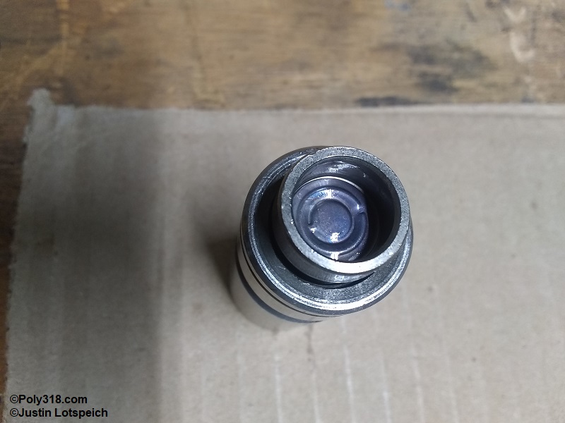
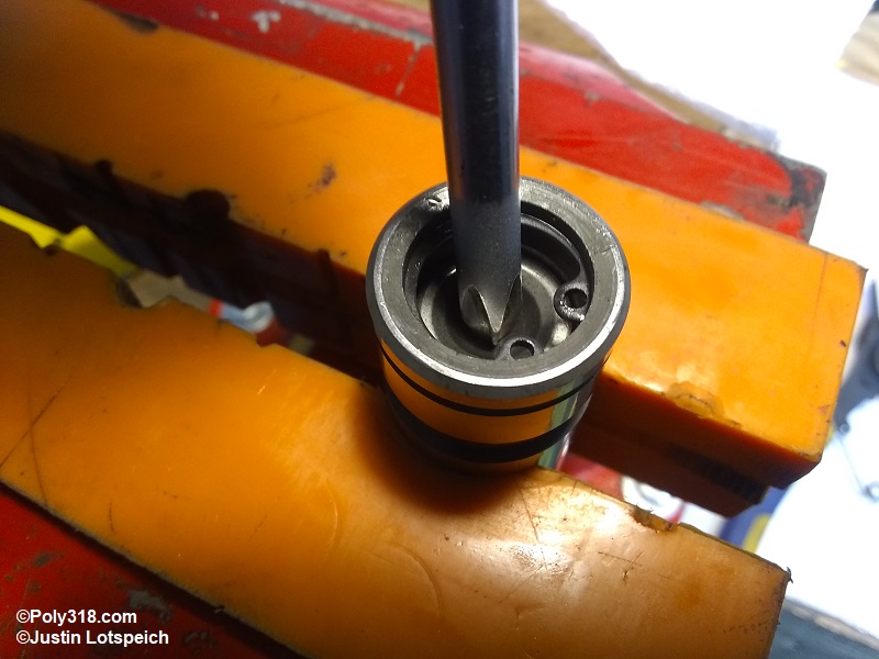
Secure the lifter in a clean soft-jaw bench vise. Slide the retainer over a clean Phillips screwdriver, press down on the plunger cup enough to clear the retainer groove, and install the retainer (Figure 7u). This process may require using a clean, small flathead screwdriver to chase the retainer around into place since the retainer should be an extremely tight fit. Look for any metal shavings from the retainer and blow them off as necessary.
Compress the plunger a couple times with the screwdriver. The plunger should smoothly move up and down with strong resistance from the spring. If the plunger sticks or does not return up against the retainer, there is an issue requiring diagnosis. If the plunger operates properly, remove the lifter, wipe off the body, and box or bag it until installation. Warning: Do not soak the lifters in oil or pump them while in an oil bath to prime them since it is unnecessary and can actual cause problems upon startup due to lifter pump-up. When we prime the engine oiling system, the lifters will receive the appropriate oil.
Camshaft Cleaning and Inspection
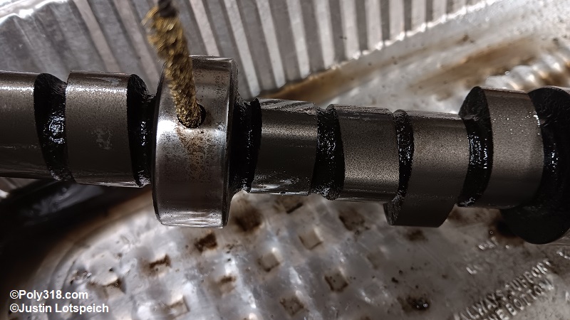
Even if the camshaft is reground or new, don’t trust the oil passages are clean. Use a pick and rifle brush to scrub the oil passages with solvent to remove all debris and oil, especially in the inside intersection where the two oil passages meet to feed the cylinder heads that collects a lot of grime (Figure 8a). This photo is of a reground cam I received supposedly cleaned, wrapped in plastic, and “ready for installation,” which you can see has a lot of grime left in the oil passages.
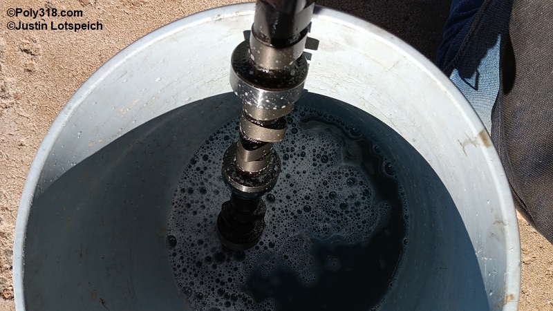
Place the camshaft in a bucket of hot water and Dawn original dish soap, and scrub it including the oil passages and front threaded boss with a nylon brush and rifle brush (Figure 8b). Without letting the camshaft dry, rinse it well with clean water, flush the oil passages, and dry the camshaft and blow out the passages and threaded boss with compressed air.
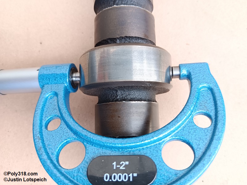
Inspect the journals for any raised edges that catch on a pick or fingernail. If journals have any raised edges, follow the polishing instructions I describe for the crankshaft to remove the edges. Measure the journals with a micrometer at three different clock positions to check for out-of-round and taper, which should fall under 0.001” (Figure 8c). If any are more than 0.001”, the journals should be ground by a machinist but not small enough to fall outside of bearing clearance spec.
Inspect the lobes for raised edges. If any has a raised edge, use a fine single-cut file to lightly ease the edge without touching the face of the lobe and clean the cam again. Bag the cleaned camshaft for later. Warning: A raised edge may cause the lifter to stop spinning and the lifter and cam to flatten.
Piston Cleaning and Inspection
Whether used or new, clean the pistons in a solvent or soapy water similar to the crankshaft and camshaft cleaning. Ensure the wrist pin bosses and any oiling and vent holes are clear. Ensure the ring grooves are free of all debris by using a pick or by breaking an old compression ring in half and using the factory square edge as a scraper. Ensure the tops are free of all carbon, but don’t put deep scraps in the tops that can cause hot spots. When clean, dry the pistons with compressed air, write the cylinder number on the top if the machinist did so and the number faded during cleaning, and bag them for later.
Oil Pump Cleaning and Inspection
While I cover blueprinting, porting, and converting the oil pump to high-pressure in another article, I go over cleaning the 1962 – 1967 M72 pump here. Even if the pump is new, it should be cleaned and inspected. For details about cleaning and inspecting the 1956 – 1961 M51 oil pump, see my other article.
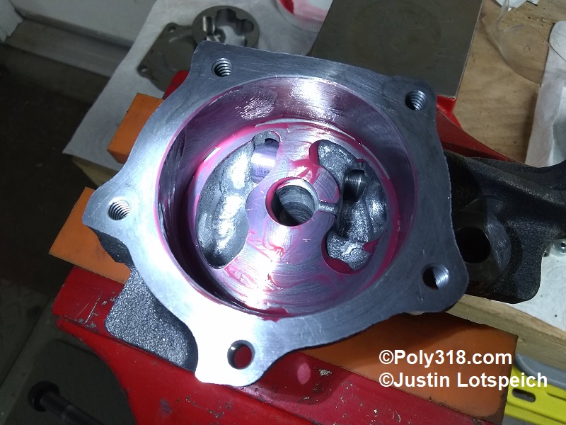
With the pump in a bench vise, remove the screws and top. Use a center punch to lightly mark the top of the outer rotor to ensure it goes back in right-side up. Remove the inner and outer rotors, clean off all oil from rotors and housing, and reinstall the rotors.
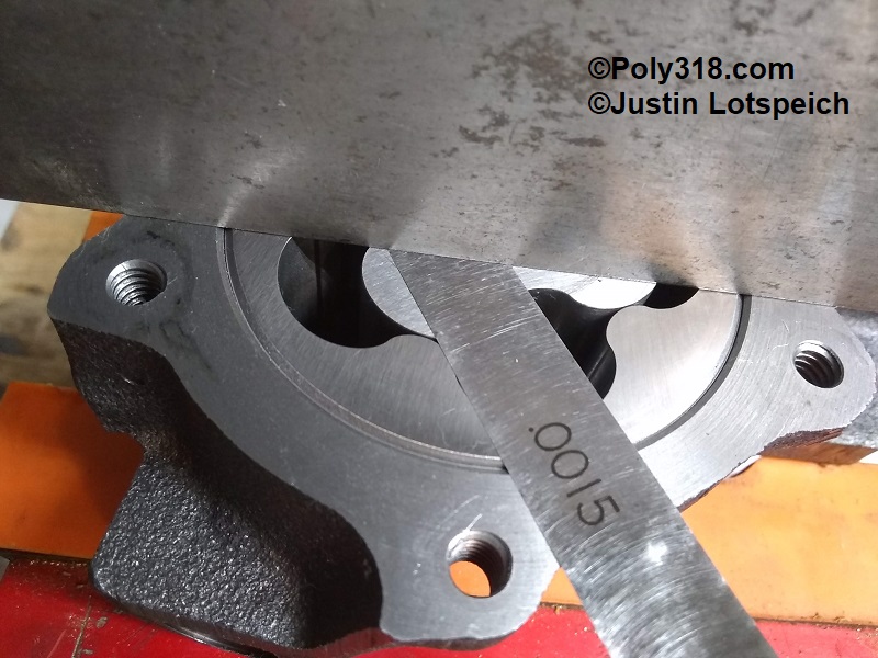
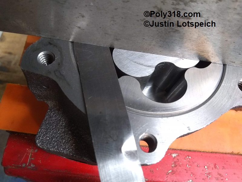
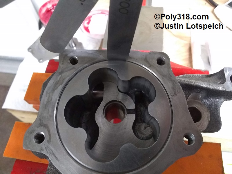
Place machinist’s straightedge across housing. Using feeler gauges, confirm the inner rotor and outer rotor clearance is 0.001″ – 0.004″ (Figures 9a and 9b). If clearance is too tight, sand the top of rotor with wet sandpaper and automatic transmission fluid or cutting oil on a flat surface, such as the straightedge. If clearance is too loose, sand the top of the housing where the cover mates.
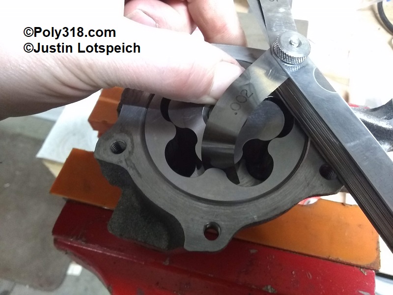
Pinch the inner rotor tightly against the outer rotor and housing. With the other hand, slide a feeler gauge between the teeth and confirm clearance is 0.001″ – 0.006″ (Figure 9c). If clearance is outside this range, discard the pump.
Remove the inner rotor and insert a feeler gauge between the outer rotor and the housing (Figure 9d). Confirm the clearance is 0.002″ – 0.012″. If clearance is outside this range, discard the pump.
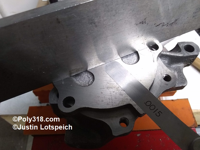
With the cover upside down, set a straightedge across the cover and confirm the clearance is 0.0″ – 0.0015″ (Figure 9e). Check clearance in the center and at four outer points, such as each of the bolt holes. If tolerance is too loose at any point, sand the cover with wet sandpaper and automatic transmission fluid or cutting oil on a flat surface until it is flat within tolerance.
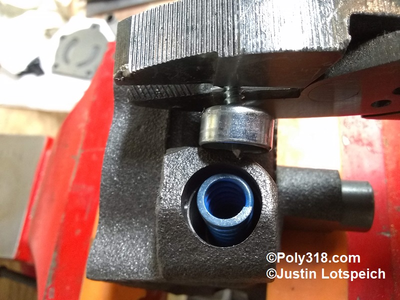
Ideally, especially if reusing a pump, you should pull the cotter pin and expansion plug in order to remove and inspect the pressure relief spring, piston, and bore. To pull the expansion plug, drill a self-tapping screw through it, pry out the screw and plug with wire side-cutters, and remove the pressure-relief components (Figure 9f).
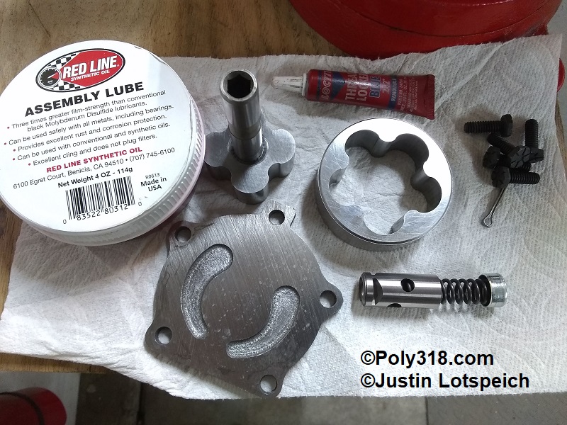
Clean the housing, rotors, cover, pressure piston, and bolts in solvent or cleaning solution (I use an ultrasonic cleaner). Blow off all residual solvent/solution, and set the parts on the cleaned assembly area (Figure 9g).
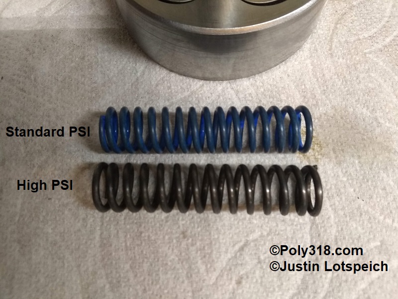
If converting the pump to high pressure, obtain a Mopar Performance high-pressure spring kit P3690944 (Figure 9h). Note: The kit does not contain the expansion plug even if the retail photo shows one.
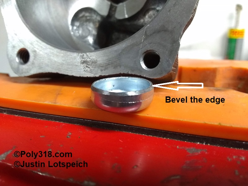
For the new expansion plug, Melling sells the expensive expansion plug, but I found that a 5/8″ Sealed Power 3813052 works and is much cheaper. Using a bench grinder or hand file, bevel the plug’s edge to allow for easier installation (Figure 9i).
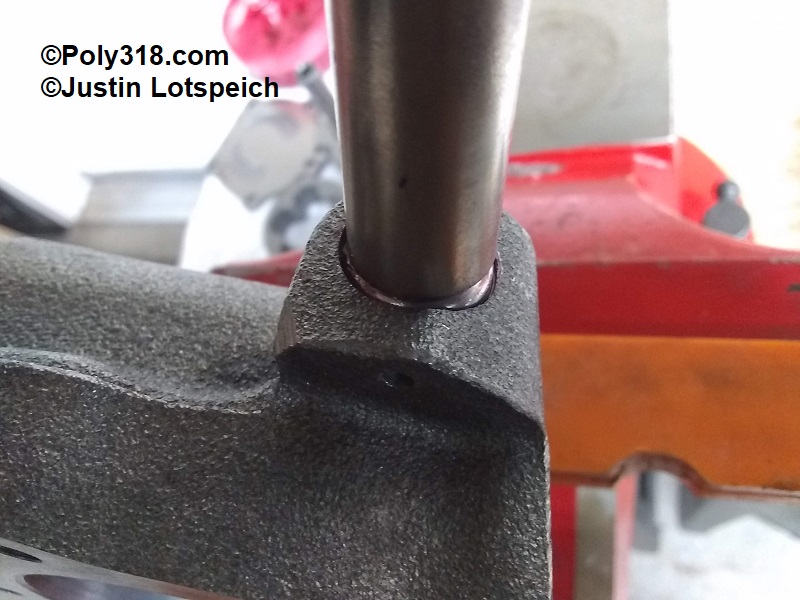
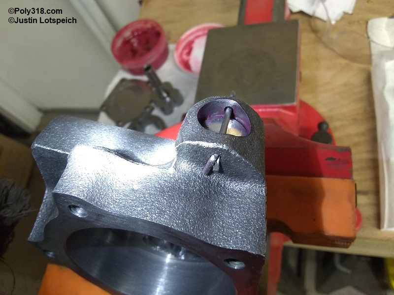
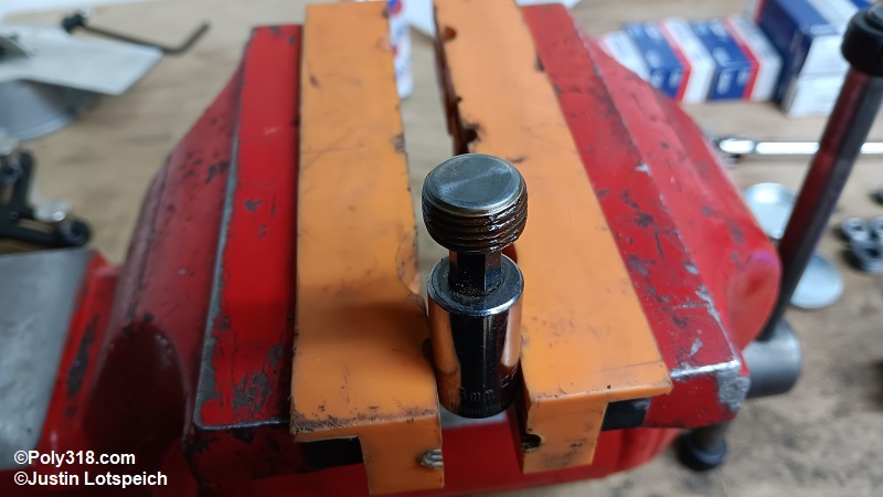
With the housing in a clean soft-jaw vise, lubricate the pressure-relief bore and piston and drop in the piston with the machined grooves end first. Drop in the cleaned high-pressure spring. Place the expansion plug with the cup side facing the spring. Drive in the plug with a socket until it just clears the cotter pin holes, and install a new cotter pin and peen over the end (Figure 9j), and install a new cotter pin (Figure 9k). WARNING: if you place the cup facing the cotter pin, you will compress the spring resulting in excessive oil pressure over 100 psi.
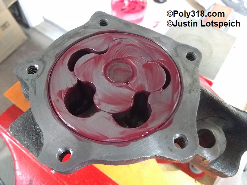
Liberally lubricate the machined floor and wall of the housing (Figure 9l).
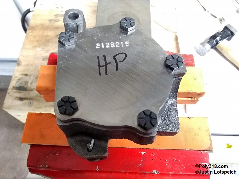
Lubricate the bottom and sides of the inner and outer rotors and the rotor shaft. Drop in the outer rotor followed by the inner rotor, and lubricate the top of the rotors. Wipe off any lubricant from the housing’s machined surface (Figure 9m). Apply Loctite red threadlocker to the cover bolts, and secure the cover torqued to 120 lb.in. in a star pattern (Figure 9n). Insert a screwdriver (1956 – 1961) or hex wrench/socket (1962 – 1967) into the shaft and spin it multiple rotations to check that the rotors spin freely without binding. Bag the pump until engine assembly.
Freeze/Expansion and Pipe Plug Installation
Clean all the block pipe plugs in lacquer thinner and allow to dry to remove all oil. With the cleaned block on a workbench, apply Permatex 80003 on the rear pipe-plug threads (Figure 10a).
Apply Permatex 80003 to, install, and torque the internal plug at the back of the left lifter oil gallery to 30 lb.ft. or until it firmly seats if before that setting before the outer plug is installed (Figures 10b and 10c).
Apply Permatex 80003 to and install all the rear pipe plugs. Torque the 1/2″ plugs to 30 lb.ft. and 3/4″ plugs to 54 lb.ft. or until they firmly seat if before that setting (Figures 10d and 10e).
Apply Permatex 80003, install the pipe plug in the oil-filter well with Permatex 80003 sealant, and torque to 30 lb.ft. or until firmly seated if before that setting (Figure 10f).
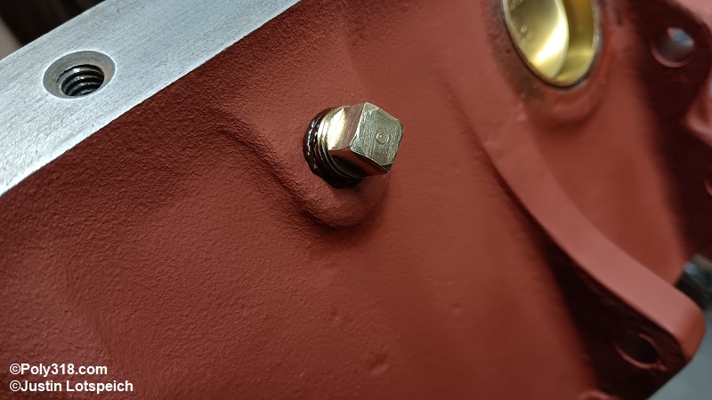
Apply Permatex 80003 to and install the coolant jacket pipe plugs near the oil-pan and torque to 23 lb.ft. or until firmly seated if before that setting (Figure 10g). I prefer to use square-head brass plugs in the coolant jackets to reduce corrosion and make future removal easier.
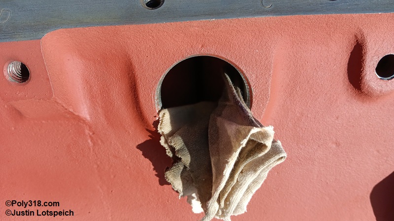
During block preparation, we already sanded the inside of the coolant holes that the expansion plugs block. Now, wipe the inside of all the holes with lacquer thinner (Figure 10h).
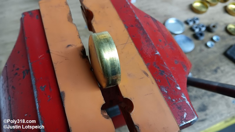
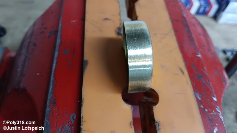
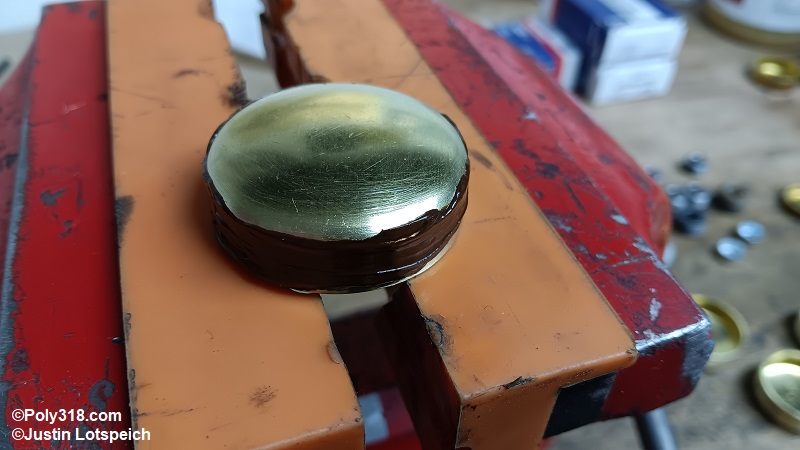
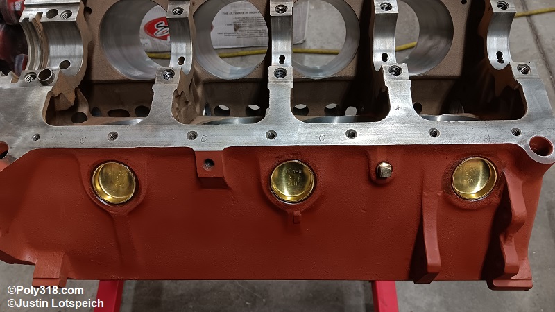
The new brass coolant expansion plugs come from the factory with shiny sides less ideal for gripping sealant (Figure 10i).
Away from the assembly area, use a red abrasive hand pad to scuff the outside of the plugs, blow them off with compressed air, and wipe the outside clean with lacquer thinner/brake cleaner (Figure 10j).
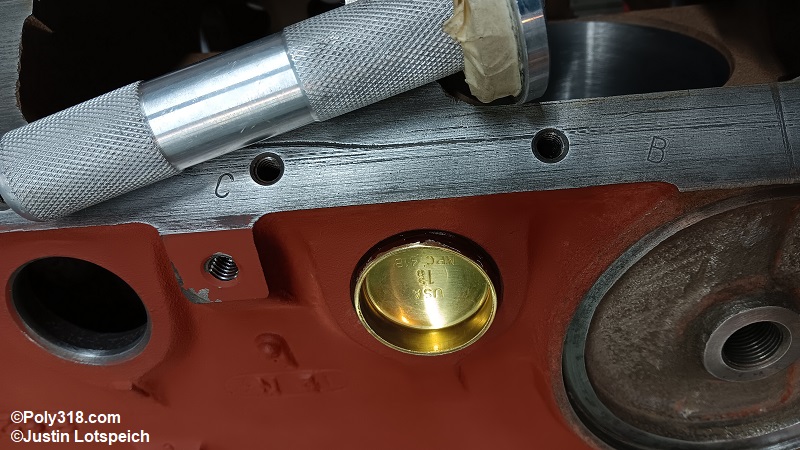
Place the engine on a quality engine stand of at least 1,000 lb. rating using Grade 8 bolts threaded deep into the bellhousing bosses. Coat the expansion plug outside wall with a thin layer of Permatex 80003 (Figure 10k).
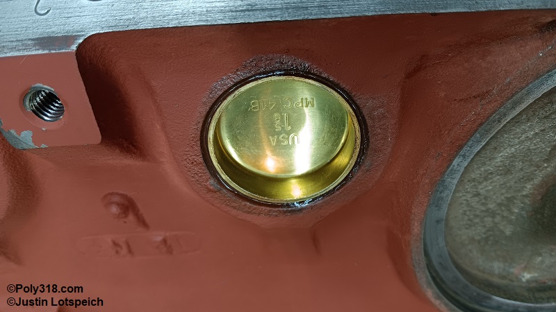
Use a bearing driver or deep-well socket that covers the entire edge of the plug to evenly drive in the plug being careful to start it square (Figure 10l). Smooth the remaining sealant into the beveled groove (Figures 10m and 10n). Warning: Don’t drive the plugs using a socket down inside the plug well since the base can crack.
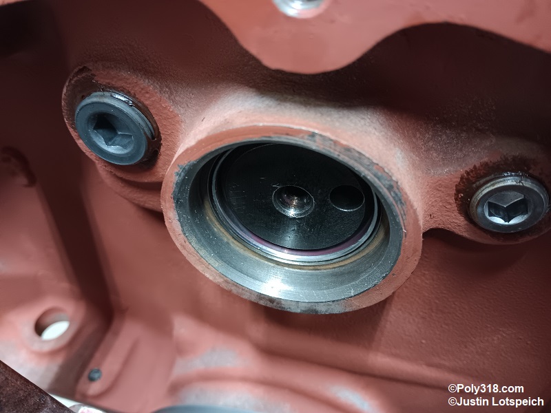
With a rag damp with lacquer thinner/brake cleaner, clean the inside of the rear camshaft bore where the plug seats of all oil (Figure 10o).
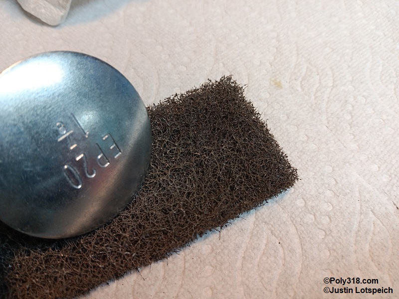
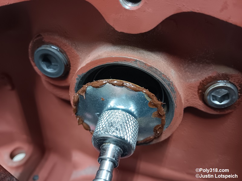
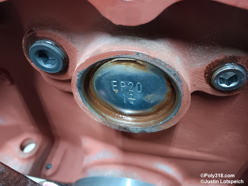
Away from the assembly area, use a red abrasive hand pad to scuff the inside, outside, and edge of the dished camshaft plug and wipe it clean with a rag and lacquer thinner/brake cleaner. (Figure 10p). The dish-style camshaft plug is installed with the convex/bulged side facing out. Place a strong magnet in the center of the plug on the convex side. Wipe a very thin layer of RTV silicone (I use Mopar 4883971) around the inside perimeter of the plug, and carefully insert the plug into the bore until it bottoms out on the block lip (Figure 10q).
Place a large flat drift at 12:00 about 1/4″ in from the outside of the plug, remove the magnet, and gently hammer the drift to crush the plug just a little. Holding the plug in with one hand, move the drift to the 6:00 position and crush that side a little. Move to the 3:00 position, then 9:00, and then work around the entire perimeter until the center portion of the plug has flattened out and you can hear and feel that the plug is firmly expanded (Figure 10r and 10s). Apply and smooth a bead of RTV silicone on the outside perimeter of the plug and block to finish the seal. Warning: Don’t hammer on the very center of the plug, and don’t crush the plug to the point where it concaves toward the cam since it can bind on the camshaft.
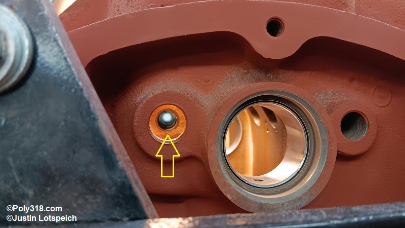
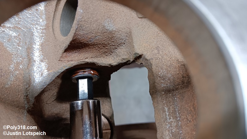
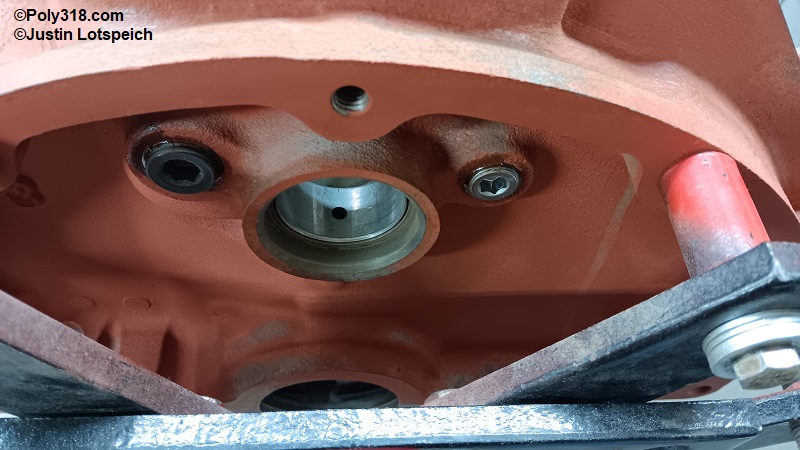
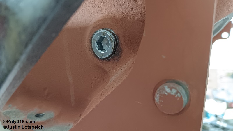
Distributor Intermediate Shaft Bushing Installation
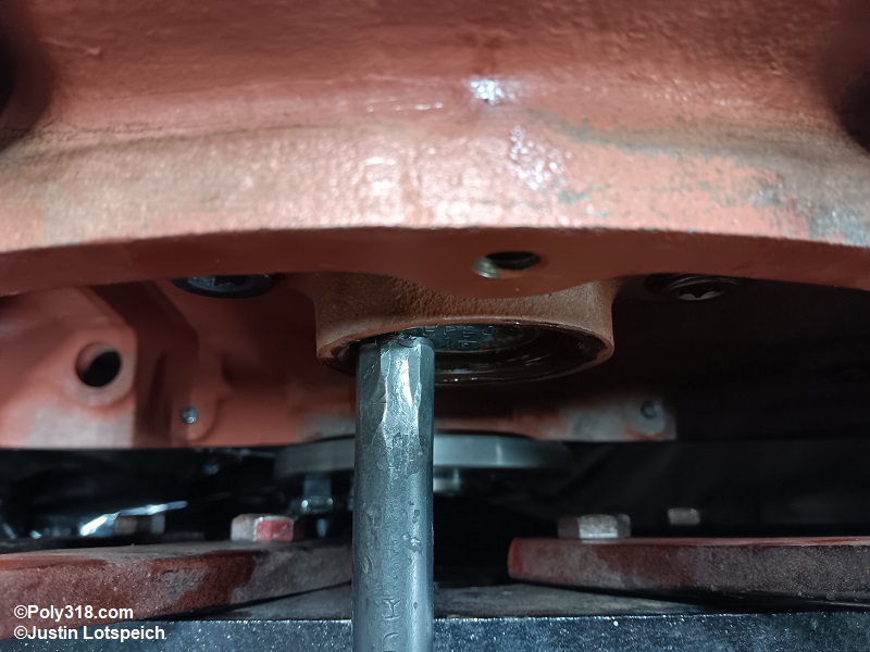
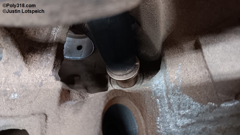
Select a deep-well socket and extension that covers the center of the distributor intermediate shaft bushing. Align the cleaned new bushing square with the bore (Figure 11a).
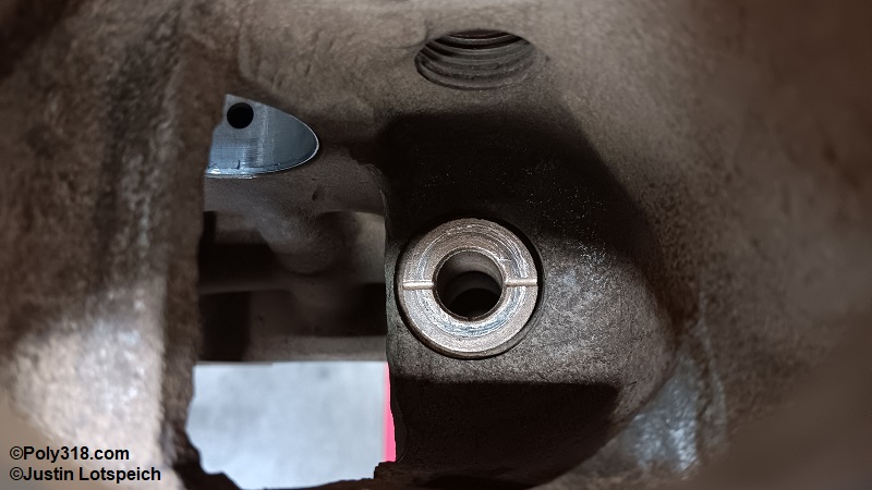
Gently hammer the bushing in from the top until it seats being careful to start and drive it square with the bore (Figure 11b).
Insert an air nozzle through the underside bore and blow out any shavings (Figure 11c).
Oil Filter Adapter Installation
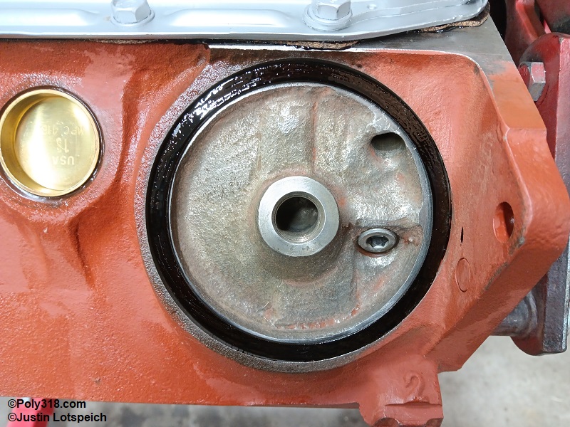
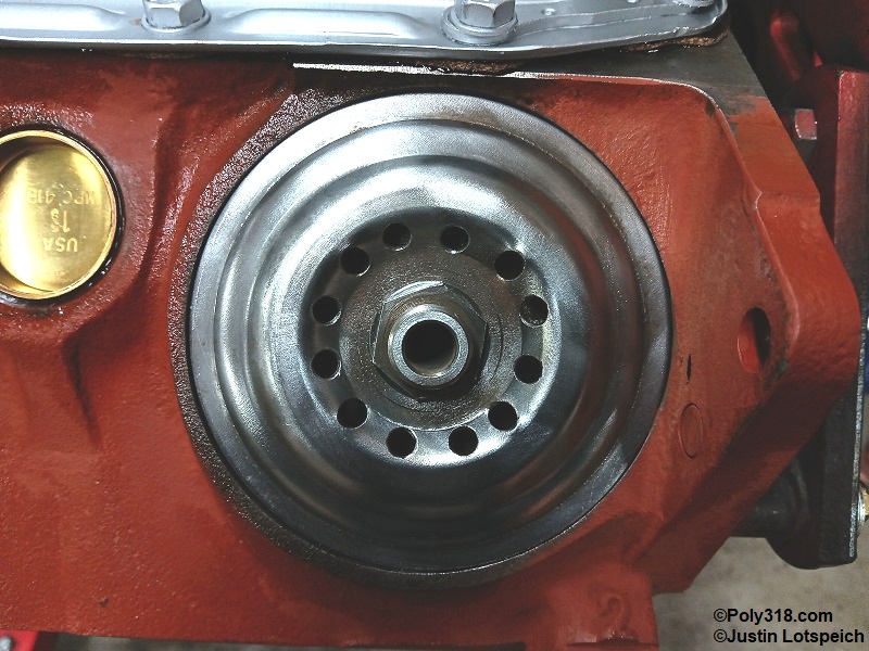
I cover modifying the spin-on filter adapter for higher flow in another article on performance oil system modifications. For spin-on filters, lay the oil filter adapter fiber gasket on a piece of cardboard and brush one side with Permatex 80019 gasket maker. Immediately flip over the gasket and coat the other side. Hang the gasket from something and let it tack up until the liquid doesn’t transfer to a finger. Warning: Do not use a rubber gasket because they commonly squeeze out and leak.
Rotate the engine block where the filter points straight up. Set the fiber gasket into the well, and set the clean adapter plate onto the gasket (Figure 12a). Inspect that there is an approximate 1/8” gap between the plate and the block at the center outlet hole. This gap is necessary to allow the bolt to compress the plate and create a tight seal on the gasket. If the plate is tight against the block, either construct a round jig out of PVC or steel pipe to bend a dome into the plate, or obtain another plate since it will leak.
Place a couple drops of Loctite red thread locker onto the bolt threads that go into the block, and torque the bolt to 30 lb.ft. (Figure 12b).
Cylinder Head Assembly
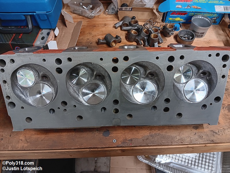
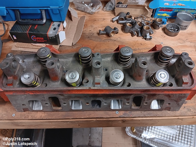
These cylinder head assembly instructions assume you or a machinist have already set valve spring height, confirmed closed and opened seat pressures, and that the heads have been disassembled for final cleaning with the valves, springs, retainers, keepers, and any spring shims kept in sets for the chamber to which they belong. With the clean bare head on a bench, line up the four corresponding cylinder sets of components in order.
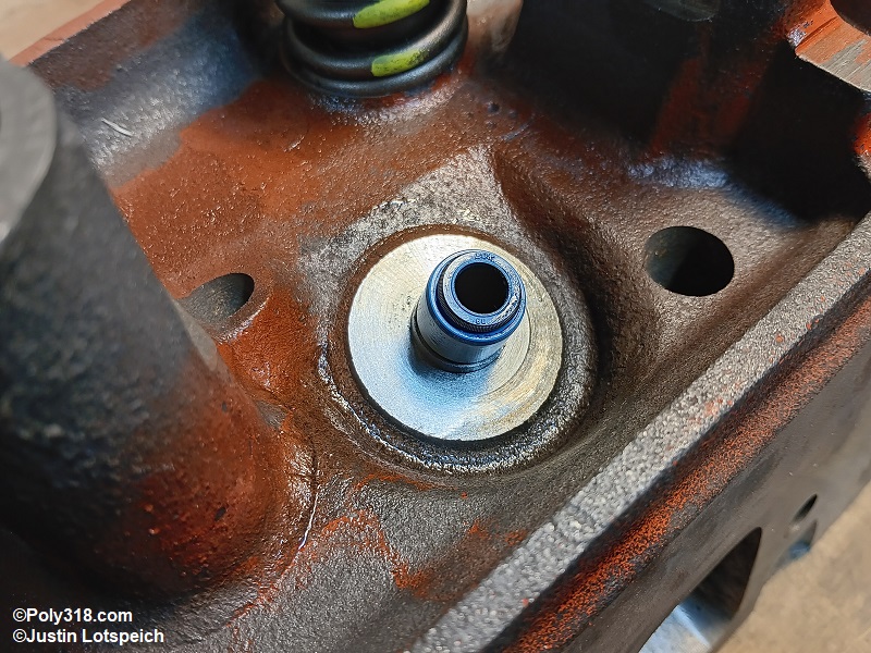
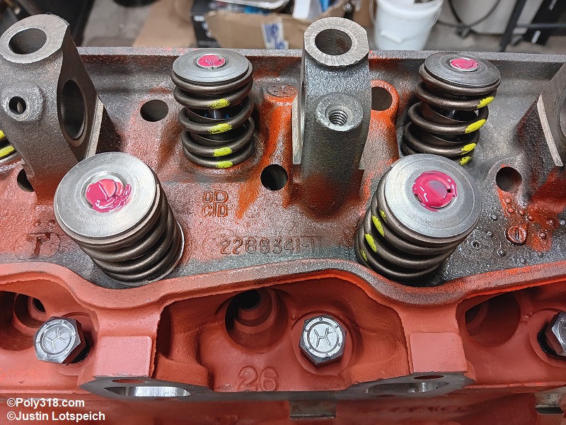
If using positive valve-stem seals, lightly coat the insides with clean motor oil and press them down onto the guides. Use a clean deep-well socket and rubber mallet to gently drive the seals down until they seat (Figure 13a).
Wipe the cleaned valves and seats with a dry lint-free rag and blow them off with compressed air. Inspect the stem tips for clean chamfers and the keeper groove(s) for no raised edges. Ease any burrs with a fine single-cut file away from the assembly bench so they do not cut the seal, and reclean the valve. Apply a skim coat of quality assembly lubricant (I use Red Line 80312) to the valve stems from the tip to about 1.5” above the head (Figure 13b). Warning: Applying too much lubricant will cause the lubricant to run down and burn onto the valve and seat sealing surfaces and can cause a burned valve.
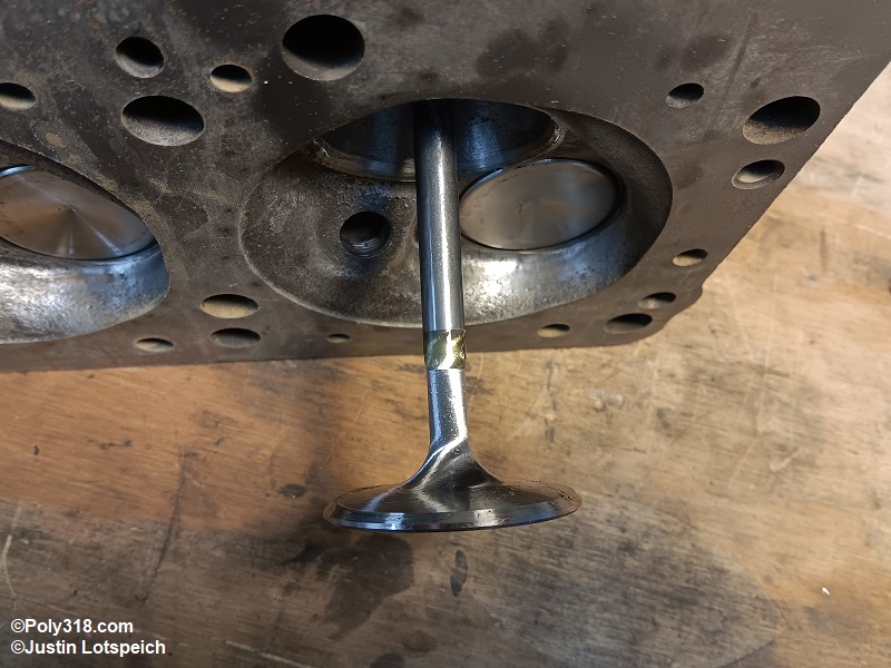
Working on one cylinder at a time, insert the valve stem into the guide and very gently twist the tip and keeper groove(s) through the seal being careful not to cut the seal lip. If using umbrella seals, twist the new seal over the stem down until it hits the guide.
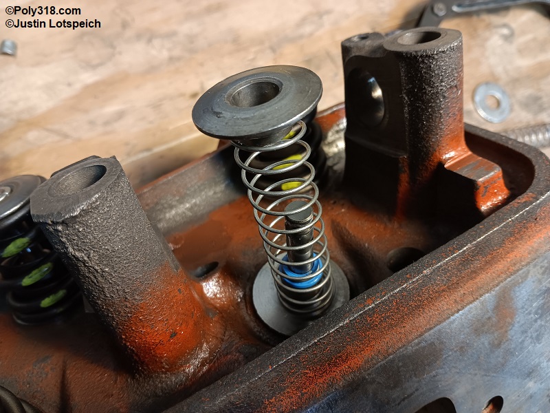
For all chambers except for cylinder #1, slide on the cleaned spring adjusting shim if equipped, cleaned new spring, and cleaned retainer. Warning: If using dual springs and a flat-tappet camshaft/lifters, leave out the inner spring for camshaft break-in to lighten the pressure applied to the lifter; the inner spring will be installed after break-in.
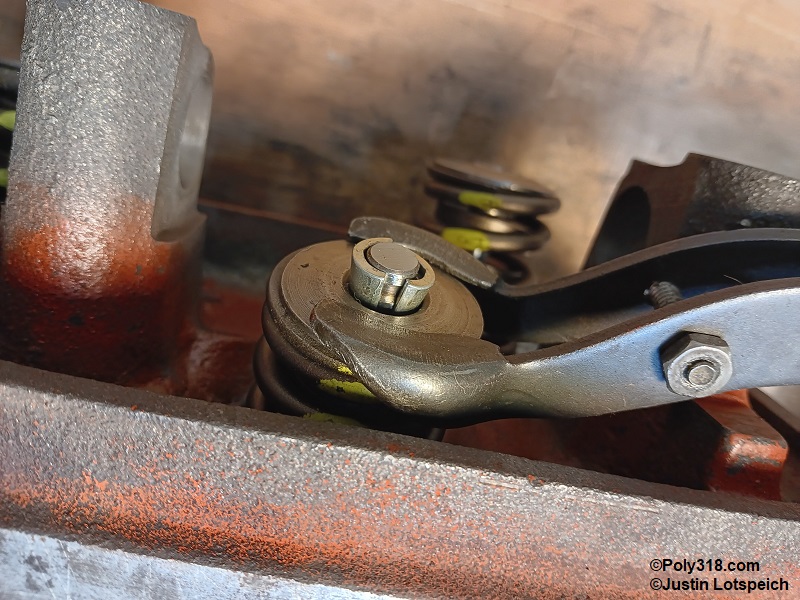
Holding the components in place with one hand, install the spring-compressor tool and compress the spring until the keepers have room to slide in (Figure 13c). Very slowly release the compressor being careful not to pinch fingers between the keepers and retainer. Repeat the process down the head except for cylinder #1 being careful to install the components with the correct valve in the correct chamber.
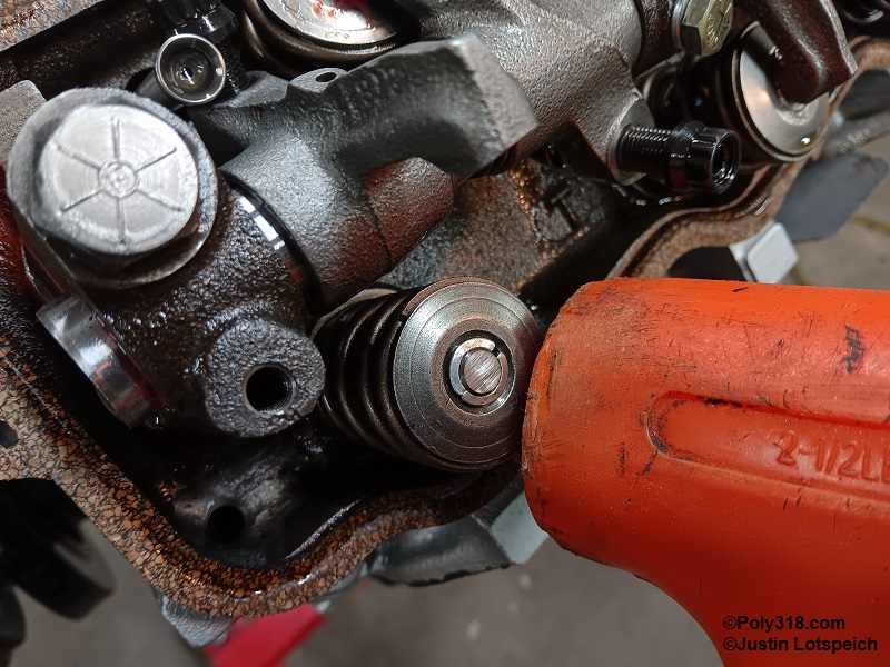
When finished, roll the head upright on the bench, and use a clean rubber mallet to lightly strike the very edge of the retainers once to ensure the keepers are seated. The purpose is to tilt the retainer and not to open the valve (Figure 13d). Repeat the process for the other head (Figures 13e and 13f).
Place a dab of assembly lubricant on each of the valve stem tips (Figure 13g).
Cylinder #1’s valve-spring assembly differs in order to check valve-to-piston clearance and rocker-arm geometry. For cylinder #1, install cleaned light-weight springs over the intake and exhaust valves (I use 3” x 3/4″ x .0625” gauge springs from the hardware store). Hold the valve head with one hand, compress the cleaned retainer down onto the spring, and install the cleaned new keepers. Push the valve tip down a couple times to ensure it moves easily (Figure 13h).
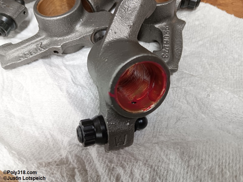
Line up the cleaned rocker arms in a row of intake and a row of exhaust. Apply a skim coat of quality assembly lubricant to the bore of each rocker arm, the two shafts, and the tower sides of the cylinder heads (Figures 13i and 13j).
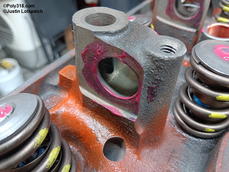
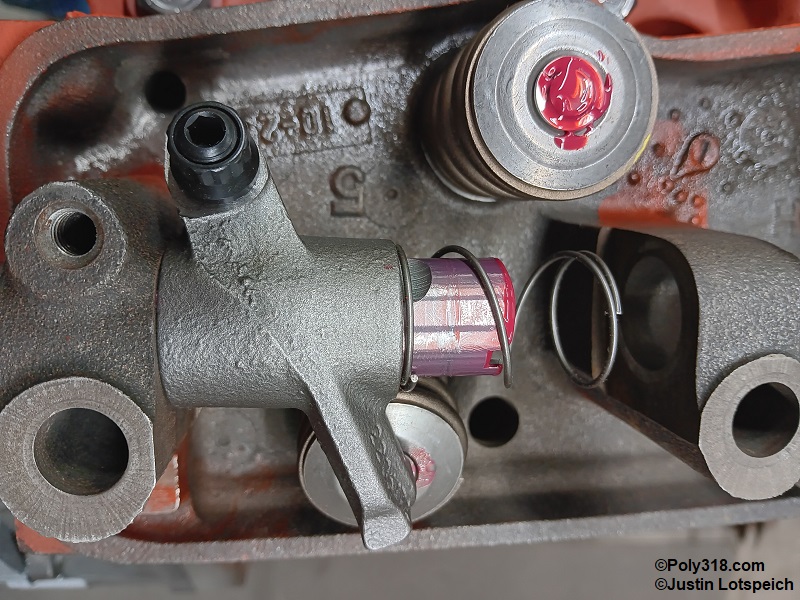
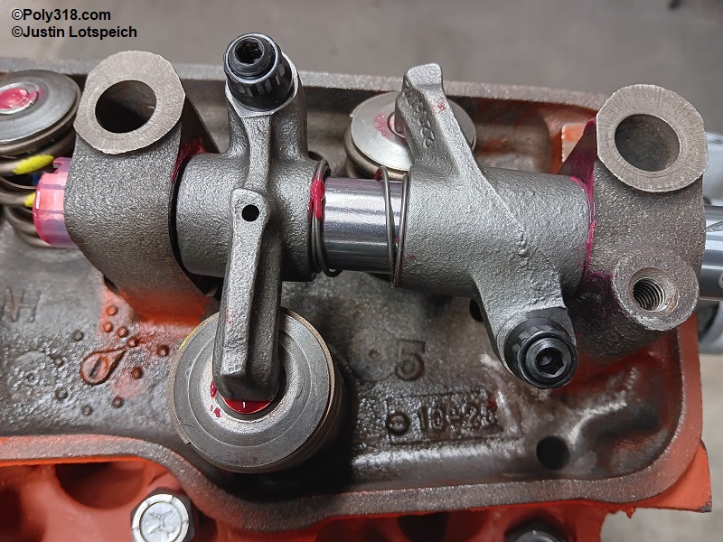
Position the shaft to where the locking-pin hole will align with the tower hole, and start the shaft into the tower. Gently twist the shaft through the first tower enough to slide on the applicable rocker arm, push it more to install a cleaned spring, and push it through the second rocker arm into the next tower (Figures 13k and 13l). Repeat the process down the line. Leave the locking pin out of the shaft at this time in order to install the head bolts since the shaft must align with the head bolts.
Camshaft Installation
Camshaft installation is easiest with the crankshaft out. Before installation, check for bind. Without assembly lube, insert the cleaned camshaft into the front bearing, take hold of the back of the camshaft with the other hand from inside the block, and guide the camshaft through all the bearings being extremely careful not to nick the bearings with the gear and lobes. Note: The design of the A-block and LA camshaft is such that an installation tool or long bolt on the front of the camshaft is not necessary since the front has a snout.
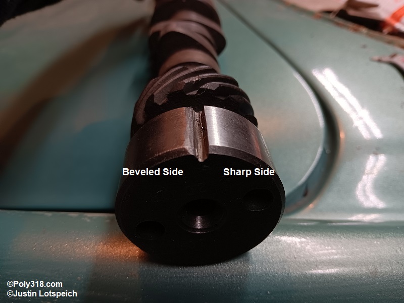
Rotate the cam by hand feeling for binding. Slight dragging without lubricant is not problematic since the soft bearings will wear into the cam journals. If the cam spins without binding, carefully remove it and continue with installation. If it binds, the bearings must be shaved. If you don’t have the dedicated tool, take an old A or LA camshaft, and use a cut-off wheel to carve an 1/8” wide x 1/4” deep groove parallel with the shaft across all the journals. Use a grinder or file to bevel the right side of the groove when looking at the front of the camshaft to remove the edge. Run a flat file across the face of the journals to remove any burrs sticking up that would damage the bearings, but keep the one edge sharp (Figure 14a). Insert a bolt into the cam snout, insert the camshaft into the front bearing, and when the cutting groove contacts the bearing, begin turning the camshaft with a wrench clockwise while gently and slowly pressing the cam in to shave the bearings. Continue this process until the camshaft is fully installed, and spin the camshaft until it no longer binds. After carefully removing the camshaft, blow out all shavings from the bearings, oil galleries, and block, wipe the bearings clean with a lint-free rag and lacquer thinner, and blow out everything again.
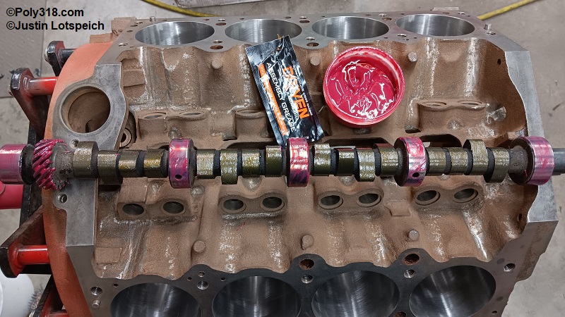
Liberally coat the cleaned camshaft bearings, journals, and gear with quality assembly lube. Liberal coat all the lobes except for cylinder #1 (you will lube after degreeing the camshaft) with a quality moly based assembly lube (I use Driven 00732, Figure 14b).
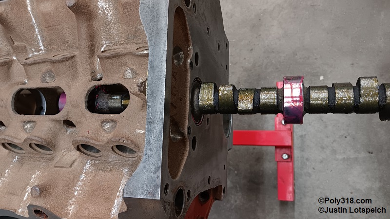
Install the camshaft holding the snout and guiding it back with the other hand being extremely careful not to nick the bearings with the gear and lobes (Figure 14c).
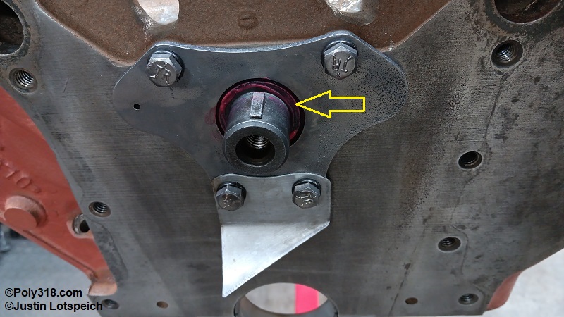
Closely inspect the camshaft at the large hole in the thrust plate. When the thrust plate is placed over the camshaft snout, the plate’s hole should largely be filled with metal, as shown in Figure 14d. Some A-block camshafts, like the one in this engine, have a machined standoff incorporated into the cam snout that fills the thrust plate hole and holds the sprocket away from the plate for clearance. This type of camshaft does not use a separate spacer.
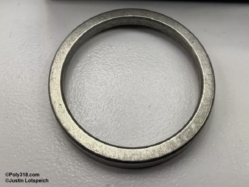
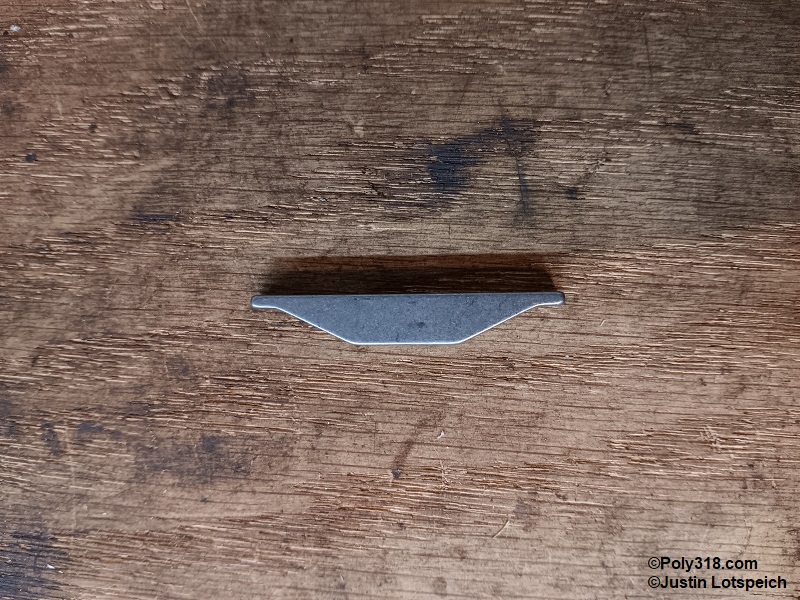
Other A-block cams have a flat face on the camshaft and use a separate spacer ring that slides over the snout and is locked in place by the woodruff key (Figure 14e). This spacer must be used for this type of camshaft or the timing gear will bind on the thrust plate. If the spacer is missing, pry out the woodruff key using a pair of side-cutter wire cutters, slide on the cleaned, lubricated spacer ring, and gently tap the woodruff key back into place with a clean hammer.
Apply assembly lube to the inside of the thrust plate and install it over the snout. If applicable, install the oil director tab over the thrust plate. Place a drop of Loctite red threadlocker onto the bolt threads, and torque them in an “X” pattern to 180 lb.in. (Figure 14f). Spin the cam a few times to ensure it doesn’t bind. Endplay will be checked later after the timing sprocket is installed since doing so now will give an inaccurate measurement.
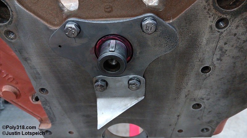
Crankshaft Installation and Measuring/Adjusting Endplay – 15
Before the final crankshaft installation, endplay and bearing main journal clearance must be checked and adjusted if necessary. With the block upside down, install dry, cleaned main bearings in the block and caps being careful to follow the manufacturer markings for “upper/block” and “lower/cap” halves. Blow off the bearings with compressed air to remove any shavings on the ends.
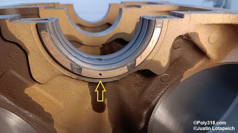
If you completed the thrust-bearing oiling modification I recommend and cover in another oil-modification article, ensure the correct drilled half is placed in the block (Figure 15a).
Holding the dry, cleaned crankshaft at the front snout and rear flange, gently set it straight down into the bearings. Align the main caps with the numbers on the left (driver) side and any arrows forward so the nubs in the bearing halves are not aligned, and install the #1, #3, and #5 main caps with one end tight against the block, and tap down the other end snug with a rubber mallet (Figure 15b). Tighten the dry bolts with a hand ratchet just until the caps snug down on block (approximately 10 lb.ft.).
With a heavy rubber mallet or block of wood and hand sledge, firmly knock the rear crankshaft flange forward three times to align the #3 thrust bearing halves against the block web (Figure 15c). Warning: Ignoring this alignment step can create an issue where the bearing halves aren’t on the same plane and the crankshaft runs on only one half of the thrust bearing wall creating overheating and premature wear.
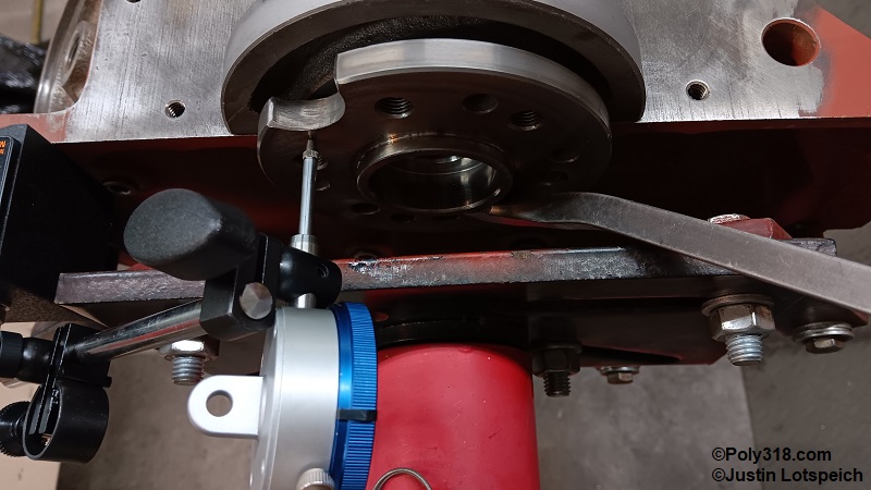
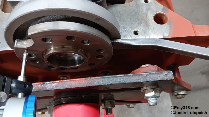
Starting on cap #3 working back and forth on the bolts, torque the bolts to 30 lb.ft., and then torque the two other caps. Set a dial indicator on the rear of the crankshaft flange and zero the gauge.
Using a pry bar between the engine stand plate and crank flange, gently but firmly pry the crank forward and zero out the gauge (Figure 15d).
Use a pry bar between the block and rear crankshaft flange and gently but firmly pry the flange back (Figure 15e). Record the gauge reading. Repeat prying the crankshaft forward, zero out the gauge if necessary, and pry back again, and record the gauge reading. Repeat this process until two measurements in a row are identical. This is the crankshaft endplay which should fall between 0.002” – 0.007” with 0.010” as the absolute maximum. My engine had 0.0055” endplay.
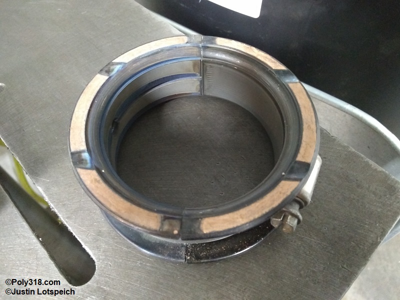
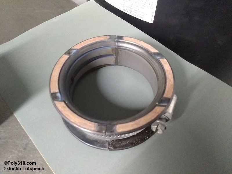
If endplay is too tight, the front side wall of the #3 thrust bearing must be sanded. Remove the crankshaft and #3 bearings, and use a permanent marker to place an X mark on the back thrust side of each half. Place the halves with the back/X-side down on a dead flat surface such as a drill-press table, machinist’s straightedge, or thick metal or glass plate. Firmly tighten a hose clamp around the bearings (Figure 15f). Use a micrometer to measure and record the width of the bearing from front to rear thrust face for a baseline of how much material you must remove.
Place a sheet of 400 or 600-grit wet/dry sandpaper on the flat surface, and wet the paper with WD-40. Flip over the bearing with the front face down (X-side up), and use a figure 8 pattern without applying pressure to gently sand the front face (Figure 15g). Occasionally stop, wipe off the thrust face with a paper towel, and measure the overall width until enough material is removed to place endplay within tolerance. When finished, thoroughly clean the bearing halves with soapy solution and blow them dry. Install the bearings and crankshaft, and repeat checking the endplay as described above to confirm it is within tolerance.
With endplay set, move onto measuring the bearing clearance. Remove the caps and crankshaft by wrapping on the cap ends (at the side of the block) to pop them up, install all main caps with dry bearings, and tap the caps down with a clean rubber mallet. Apply a coat of ARP Ultra-torque onto the caps around the bolt holes and a bead on the bolt threads, and torque all bolts following the pictured sequence to 30, then all to 60, and finally all to 85 lb.ft. (Figure 15h).
Use a dial bore gauge to measure each bearing at three different clock rotations of 10:00, 12:00, and 2:00 writing down the results (Figure 15i). The measurement can be taken with a telescoping gauge and outside micrometer carefully, but the process is more difficult and usually slightly less accurate.
Go back to your measurement log, and subtract the crankshaft main journal diameters taken earlier from the bearing diameters to get the clearance, which should fall between 0.0005” – 0.0025”. Performance engines often shoot for the looser side of 0.002” – 0.0025”. My engine had between 0.0018” and 0.0020” on the journals. If the clearance is outside of tolerance, obtain different sized bearings and recheck clearance. Note: An alternate but slightly less accurate method to measure clearance is Plastigauge, whose instructions are available through their website.
Now that clearance is confirmed, remove all the caps and wipe all bearing surfaces including the thrust sides a lint-free rag and blow them off with compressed air to remove all debris. Liberally coat all bearings and thrust faces with quality assembly lube.
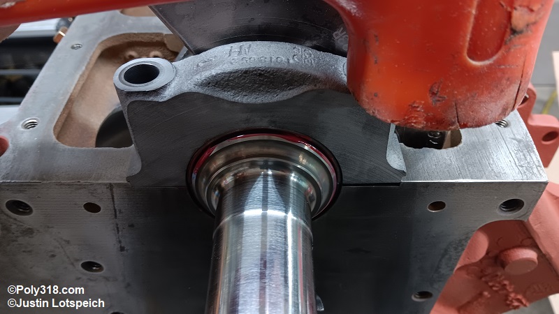
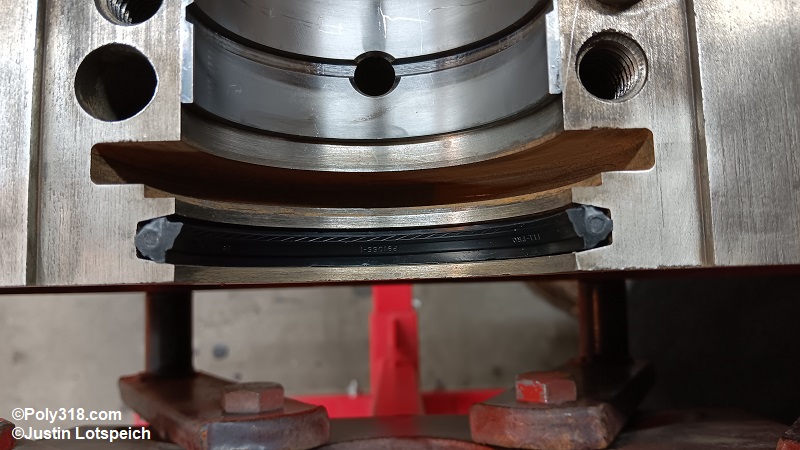
Install the dry seal half into the block with both ends sticking out of the pan rail approximately evenly with the sealing lip toward the inside of the block (Figure 15j). Install the dry new rear main seal half with wings into the #5 cap with the sealing lip facing in. Note: Some engines, like small-block Chevrolet, require the rear mail seal halves be installed rotated to where the joint doesn’t align with the block/cap joint, but the A/LA does not allow this method due to the seal wings.
Without getting assembly lube on the rubber seal joints or on the cap and block metal, wipe a very thin layer on the sealing lips and a liberal coat on the #5 main bearing. Warning: Excessive lube on the sealing lips can squeeze out and interfere with the upcoming silicone seal.
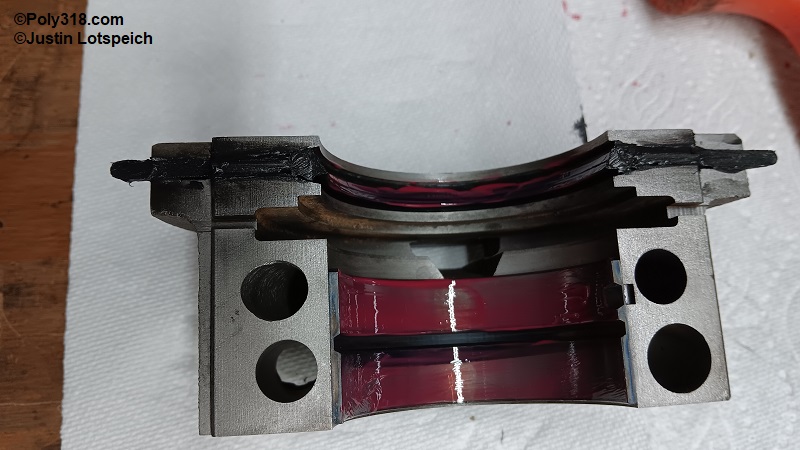
With a rag and lacquer thinner, clean the block oil pan rail on each side of the rear main cap, the bottom of the main cap and seal wings, and the four joining ends of the rubber seals to remove all oil. Place a thin skim coat of quality RTV silicone (I use Mopar 4883971) on the four ends of the seals, the two ears of the cap seal, and on the block rail. Be sure to fill the gaps between the wings and the cap (Figures 15k, 15l). The goal is to apply just enough silicone to fill any hairline gaps between the seal halves when they are mashed together. Warning: Using excessive silicone will result in silicone oozing out onto the sealing lip and crank journal and can cause a leak by holding the seal off the journal. Don’t allow the silicone to skin over by letting it set too long before installing the cap.
Wipe off all the cleaned crankshaft journals and thrust fillets with a lint-free rage and blow them off with compressed air. Liberally coat the main journals and thrust fillets with quality assembly lube. Holding the clean crankshaft at the front snout and rear flange, gently set it straight down into the bearings (Figures 15m and 15n).
Gently set the main caps onto the block and tap them into place with a clean mallet (Figure 15o).
Place a thin coat of ARP Ultra-torque compound or motor oil onto the caps around the bolt holes, and run a coat of compound/oil down the bolt threads before starting the bolts by hand (Figure 15p).
Working quickly so the seal silicone doesn’t skin over, snug the bolts with a hand ratchet just until the caps seat starting at cap #3 and moving in the sequence pictured (Figure 15q). After all bolts are snug, torque them all to 30, then all to 60, and finally all to 85 lb.ft. in the pictured sequence.
Use a razor blade to cut off the protruding rear main seal ears flush with the cap ends (Figures 15r and 15s). Warning: The crankshaft should not be rotated at all for at least 12 hours to allow the silicone to cure and block out assembly lube and for any silicone that squeezed onto the journal time to cure enough to not deform when the crank is rotated. Turning the crank can cause the silicon to smear resulting in a leak.
Piston Ring Gap Measuring and Adjustment
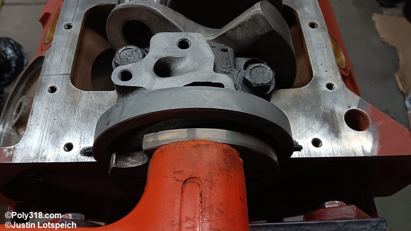
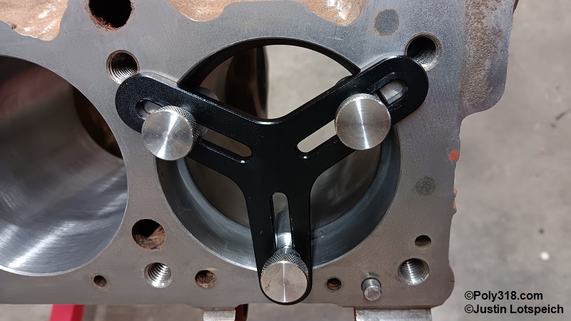
To begin measuring piston ring gap, set a piece of butcher’s paper or cardboard on a bench away from the assembly area, and write number 1 through 8 where you will set the rings. Unpackage the new compression (top groove) rings and inspect them for damage. Very gently compress a ring to close the gap and insert the ring into bore #1 about 3/4” down. With a clean ring squaring tool with one of the feet straddling the ring gap, push the ring evenly into the bore until the tool stops, and then remove the tool (Figure 16a).
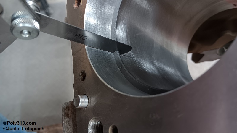
Use a set of feeler gauges to measure the ring gap (Figure 16b).
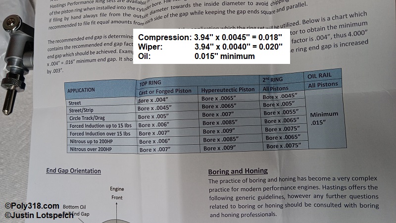
Remove the ring being careful to hold it compressed since it will try and spring out. Refer to the ring manufacturer’s recommended gap specifications for the type of induction system and type of intended driving (Figure 16c). For this engine that will see about 50% street and 50% drag-strip track time, I split the different between Hastings’ “street” and “high-performance racing” specifications to make enough expansion room for the rings on those days I am at the track many hours beating the engine at wide-open throttle. I set the compression ring to 0.019” (0.00475” x 3.94” = 0.0187”) and the wiper to 0.020” (0.00515” x 3.94” = 0.0203”).
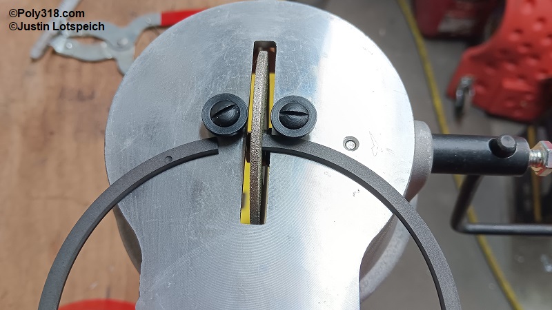
If the gap is tighter than the specification, use a hand ring filing wheel far away from the assembly area to widen the gap within tolerance (Figure 16d). When finished grinding, use a fine hand file to deburr the edges of the ring that was filed down so they don’t scrape the cylinder. Speed Tip: If the #1 ring requires filing, count the rotations of the ring filer needed to bring it to specification to make filing other rings of similar gap quicker, but do not simply grind all the rings the same without measuring assuming all rings will be the same. Each ring should be measured for its cylinder and kept organized for their specific cylinder. Repeat the process for the wiper/scraper ring (middle groove).
When finished gapping all the rings, blow off all the rings away from the assembly area, clean them by dipping them in solvent, and blow them dry. Warning: Keep them in pairs with their correct cylinder. Move the cleaned rings to a new piece of numbered paper/cardboard at the assembly bench since the old one will have grinding debris.
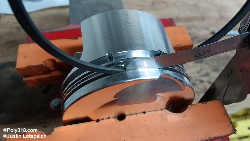
Insert the #1 compression ring into the #1 piston groove, and use a feeler gauge to check the clearance to ensure it is within the piston and ring manufacturers’ specifications (Figure 16e). If no specification exists, 0.001” – 0.003” is a typical tolerance. My engine was within the piston manufacturer’s spec at 0.003”. Repeat the process with the wiper/scraper ring and then with all eight pistons.
Piston Ring Installation
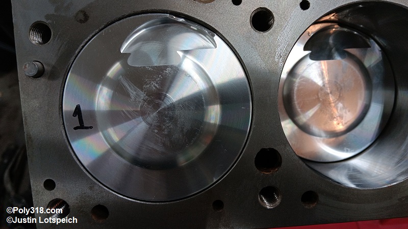
If not already done, mark a cylinder number on the top of each cleaned piston with a permanent marker. Install one pin lock into the piston. Apply a thin coat of quality assembly lubricant to the piston’s pin bores (Figure 17a).
Apply a thin coat of assembly lubricant to the cleaned pin and the pin bore of the connecting rod (Figure 17b).
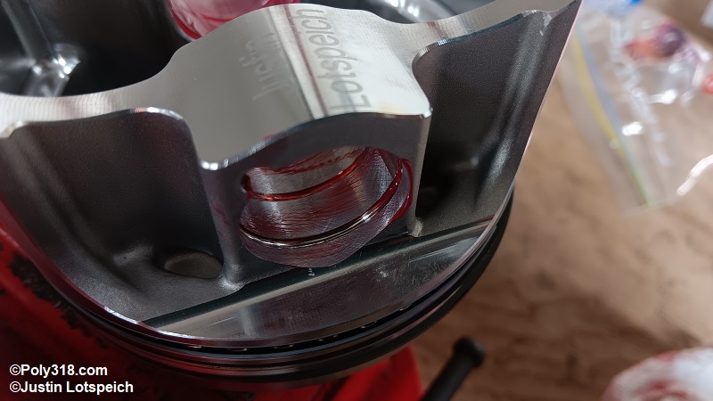
Align the piston over the rod, slide in the pin, and install the second lock (Figure 17c). Warning: For pistons with one large intake valve relief, the piston should be aligned on the rod where the valve relief faces up toward the intake manifold. The stamped numbers in the rod and cap should be on the opposite side of this valve relief to where they face down toward the oil pan when installed. Incorrectly aligning the piston may cause the intake valve to contact the piston.Proceed to assemble all eight pistons and rods.
Clamp the #1 rod in a clean soft-jaw vise so the piston skirt rests on the jaws and does not flop around. Install the new piston rings starting with the bottom oil-ring scraper. Start one end of the ring while coiling the ring up like a spring, and gently chase the ring around the piston into place being carefully not to put gouges/scrapes in the piston or kink the ring.
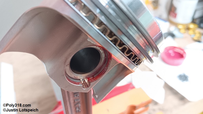
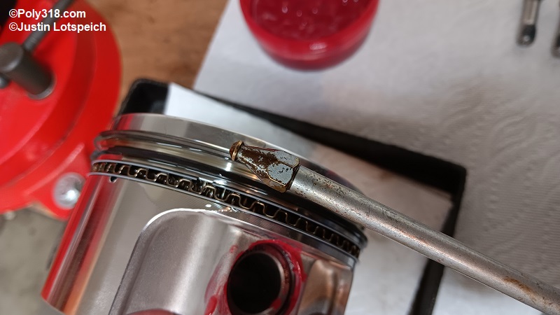
Gently spread the oil expansion ring into the groove (Figure 17d), and install the top oil scraper ring in the same fashion as the bottom ring (Figure 17e). Inspect the oil ring assembly to ensure the rings are properly seated and uniform and that the expander ring ends butt and don’t overlap. If the expander ring overlaps or if there is a gap, the ring is not the correct size for the piston.
Refer to the manufacturer instructions to properly orient the wiper ring correct-side up. Using ring-expander pliers, very gently spread the ring just enough to slide it over the piston and into place, followed by the compression ring in the same fashion (Figure 17f). Warning: Spreading the rings too much can distort or break them.
Once the rings are installed, remove the assembly from the vise, turn it sideways over a drip pan, apply a liberal amount of clean conventional motor oil into the grooves using an oil can, and spin the rings by hand a couple rotations to spread the oil (Figure 17g).
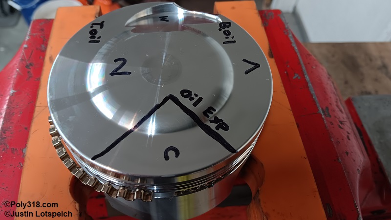
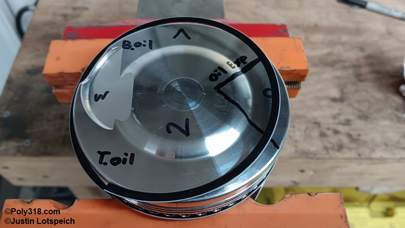
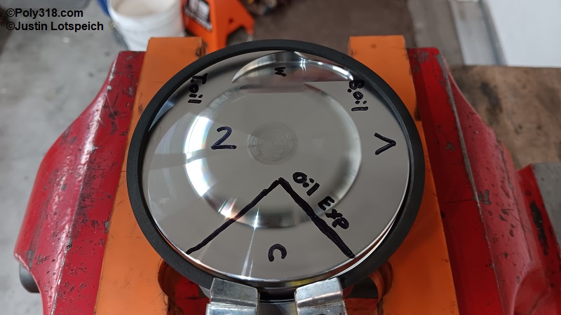
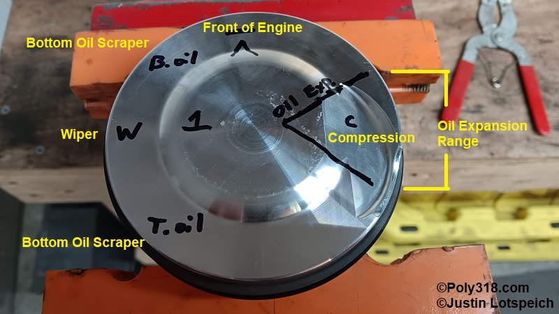
Place the rod back in the bench vise to clock the rings. I drew out the clocking positions as a demonstration. Looking at the piston top with the front of the engine at 12:00 (the crow’s foot mark in my photos), rotate each ring until it is clocked per the image: compression (top) ring gap at 3:00 (“C” in my photos), wiper (second) at 9:00 (“W” in my photos), top oil scraper at 7:00 (“T Oil” in my photos), oil expansion between 2:00 and 4:00 (the pie shape in my photos), and the bottom oil scraper at 11:00 (“B Oil” in my photos) (Figure 17h). Note that you will need to hold the oil expansion ring with a clean screwdriver so it doesn’t turn while setting the oil scrapers.
Warning: Neglecting to properly clock the rings will result in a loss of compression and increase in blow-by becoming worse the more the gaps align. When finished, set the piston assemblies in a line from #1 through #8 in a clean tray since they will pool oil.
Connecting Rod/Piston Assembly Installation
Blow out all the block cylinders with compressed air. Soak a clean lint-free cotton rag with conventional motor oil and wipe all the cylinder walls and the inside of the ring compressor tool to coat the surfaces. Warning: Do not use synthetic or synthetic-blend motor oil since it will negatively impact piston ring seating.
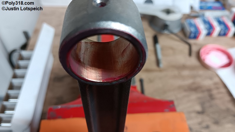
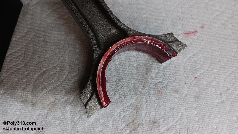
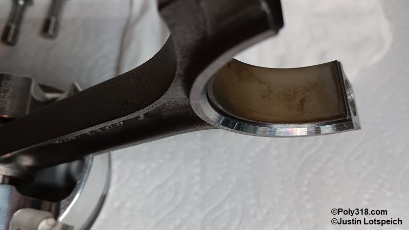
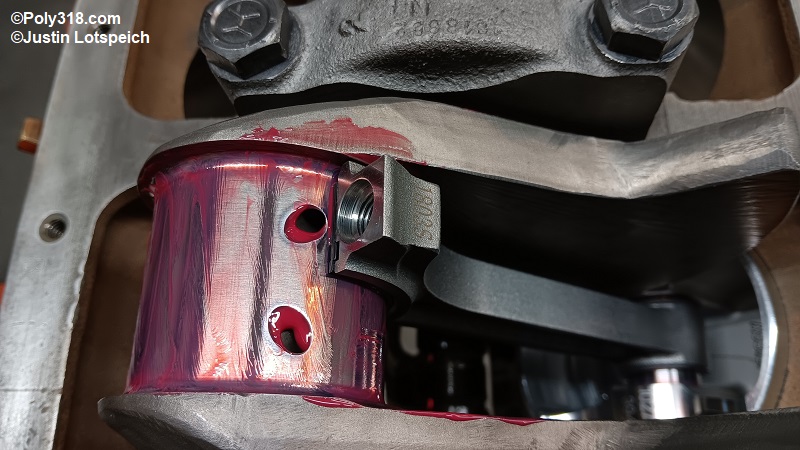
Starting with cylinder #1, remove the connecting rod cap, and liberally coat both halves of the bearing and the sides of the rods with quality assembly lubricant (Figure 18a). If the rod uses pressed-in bolts like the factory, install boots/guides to protect the crank journal. Warning: If the crankshaft has large-radius journals like on many strokers, ensure you are using the proper narrow bearings to clear the larger radius (Figure 18b).
Rotate the crankshaft throw away from cylinder #1 as if the piston were down in the hole (Figure 18c). You should have already coated the crankshaft journals with assembly lubricant, but do so if you haven’t.
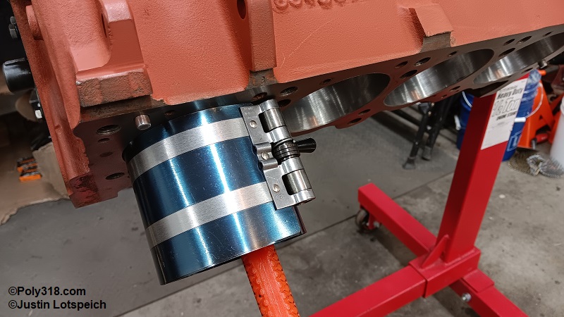
Confirm that the piston rings are still properly clocked as discussed previously, and tighten a ring compressor around the piston (Figure 18d).
Guide the connecting rod into the cylinder with the piston correctly oriented with the intake valve relief at the top (Figure 18e). Tip: Place the cotton rag used to oil the cylinders between the rod and wall to protect the wall from being scraped. Hold the ring compressor with one hand tight against the block deck, and firmly strike the piston in the center with a clean rubber mallet handle or piston mallet until all rings enter the cylinder. Be ready to catch the ring compressor. Warning: If at any point a ring pops out of the compressor during striking, stop and reinstall the compressor since hitting the ring against the block and between the compressor can break it.
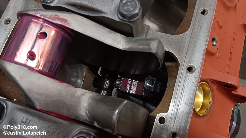
While striking the piston, be careful to guide the rod end onto the crankshaft journal so it does not mar the journal, rotating the crankshaft if necessary. Strike the piston until the bearing seats tightly onto the journal (Figure 18f).
Install the rod cap over the journal and tap it into place with a rubber mallet being careful that the cap is installed in the correct alignment with the stamped/etched numbers meeting those on the rod (Figure 18g). Install the bolts or nuts. Working back and forth in three-step sequence, tighten the bolts/nuts. For these 7/16” ARP bolts, I torqued both bolts to 20, then 40, and finally 65 lb.ft. For factory nuts, torque to 15, 30, and then 45 lb.ft.
Gently rotate the crankshaft and install the cylinder #2 piston assembly, and work back from there. Tip: As the crankshaft becomes difficult to spin by the counterweights, place a large deep-well socket over the crankshaft snout and use a breaker bar to rotate the crankshaft (the socket will catch on the harmonic damper woodruff key (Figure 18h).
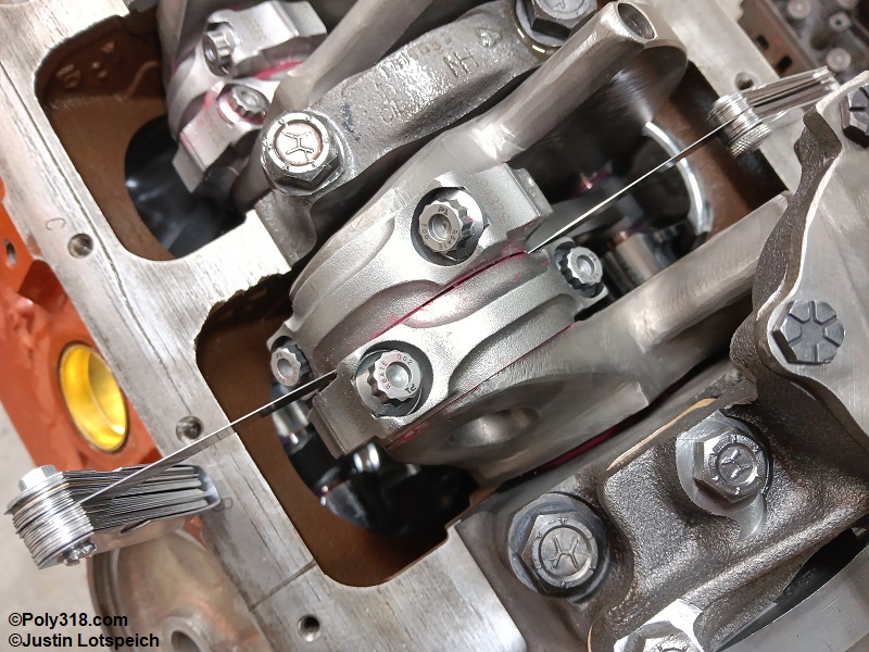
As you move along installing the pairs of rods, check the side play. Using two sets of feeler gauges, insert the same sized gauges across from each other between the rods until the thickest gauge will slide in (Figure 18i). Refer to the crankshaft manufacturer’s spec for aftermarket cranks and the factory spec of 0.006” – 0.014”. My engine had 0.024” side clearance, which fell within the crank manufacturer’s spec. Too tight a clearance can cause binding and requires the rods be machined. Contrary to what you may read online, looser clearance will not harm anything and does not cause excessive oiling and oil pressure drop. The connecting rod bearing clearance dictates how much oil seeps out through the side of the rods, not the side play.
Timing Set Installation
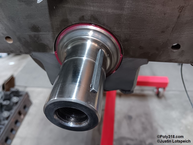
If not already done, install the crankshaft woodruff key (Figure 19a).
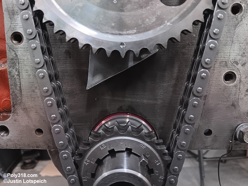
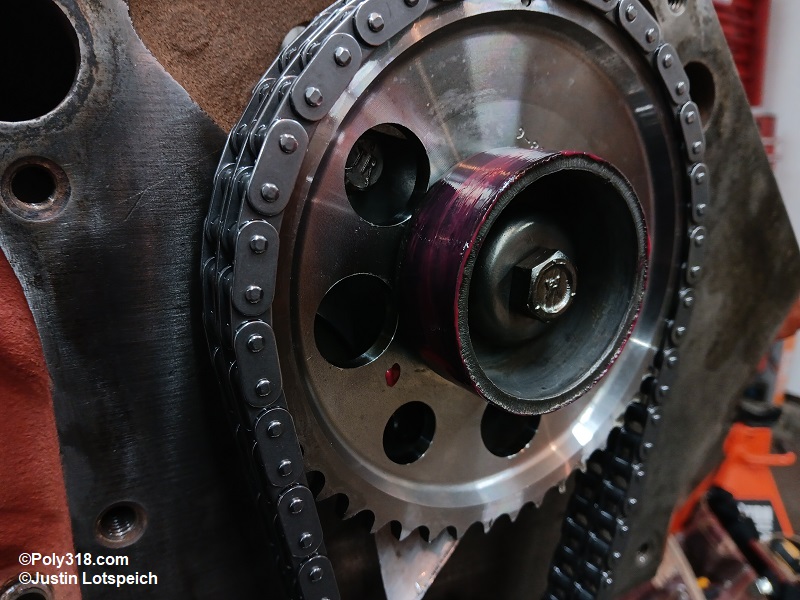
With the block upright on the stand and with the crankshaft at the #1 cylinder at the top of its stroke, barely start the cam sprocket onto the cam snout by about 1/4″ and drape the chain over it. Lower the crankshaft sprocket into the chain, and barely start it 1/4″ on the crank snout (Figure 19b). Following the timing set instructions, exactly align the marks stamped into the sprockets, which is typically the cam sprocket mark at 6:00 and the crank sprocket mark at 12:00 for 0° of cam advance. Even if the timing set has timing adjustment and your timing card or you want the cam advanced or retarded, start with the cam at 0° to properly degree the cam before adjusting timing. Pull off the cam sprocket to rotate the cam as needed to align the marks. Don’t rotate the crank to align the marks. Warning: Installing the sprockets even one tooth off makes drastic changes to cam timing, so take your time and be certain.
Once the marks are aligned, use a deep-well socket and mallet on the crank sprocket center to gently tap the sprocket on about 1/8”, push the camshaft sprocket onto the snout until it binds, tap the crank sprocket more, and continue back and forth until both sprockets are fully seated. Warning: Forcing one sprocket too much will bind the other sprocket, and excessive force should not be needed.
Install the fuel-pump eccentric over the cam snout where its center notch indexes on the woodruff key. Install the thick cup washer and bolt dry, and tighten to about 10 lb.ft. Threadlocker will be applied and the bolt torqued later after the cam has been degreed in case the timing set must be removed for adjustment.
With one hand on each side of the cam sprocket, pull and jiggle the sprocket back and forth to move endplay forward. Slide a feeler gauge between the cam sprocket and thrust plate until you find the thickest feeler gauge to slide in (Figure 19c). The camshaft endplay should fall between 0.002” and 0.006” with 0.010” being the maximum allowable. My engine had 0.003” endplay. If endplay is too tight, a thrust washer must be used between the standoff and sprocket. If the endplay is too loose, the camshaft standoff must be lathed down or the standoff spacer ring sanded as described in the section regarding the crankshaft thrust bearing.
Setting Cylinder #1 True Top-Dead Center
To properly align the harmonic damper line with the pointer mark and to degree the camshaft, which are both necessary for a quality rebuild, you must locate true top-dead center (TDC).
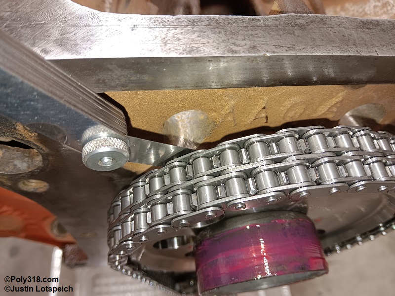
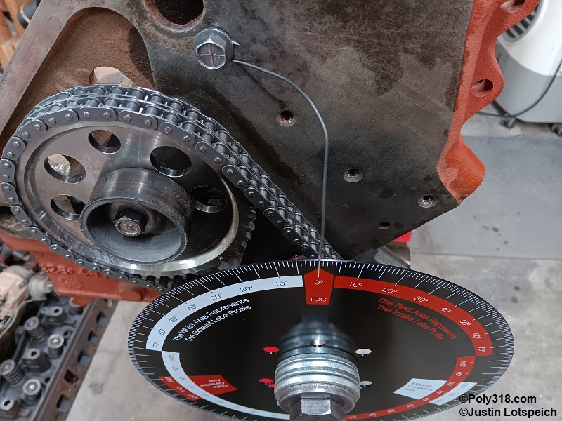
Rotate the crankshaft until piston #1 is about 1/4” down from the block deck and both the intake and exhaust cam lobe heels are visible through the lifter bores, as in both valves are closed with the cylinder ready to fire. Cut a length of rebar tie wire or solid copper wire, and twist an eye in one end with needle-nose pliers. Bolt the pointer to the block using a water pump or accessories bolt boss (Figure 20a).
Install the degree wheel onto the crankshaft snout with the correct bolt and washers hand tight. The degree wheel hole should be tight with the bolt and not be able to walk around or the degree measurements will be inaccurate.
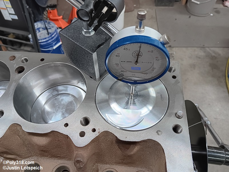
Secure a dial indicator magnetic base on the deck with the dial indicator centered on, parallel with, and touching the piston. Warning: Placing the indicator anywhere but the center parallel with the piston travel will give an inaccurate reading depending on how much the piston rocks.
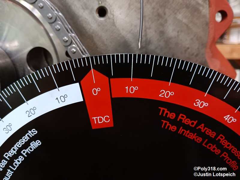
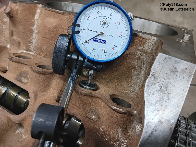
Use a breaker bar on the crankshaft bolt to slowly rotate the crankshaft clockwise while watching the gauge, and stop as soon as the needle stops moving. Zero out the dial indicator (Figure 20b). Position the wire pointer and the degree wheel where the pointer and 0°/TDC mark align. Hold the crank with a pry bar across two bolts in the rear flange and tighten the crank bolt until snug where the degree wheel does not spin. Note that the wheel may try to turn with the bolt; if it does slightly, reposition the pointer to align with the wheel’s 0°/TDC.
With the dial indicator set at 0.00”, use a prybar cross the rear flange bolts to rotate the crank counterclockwise until the gauge reads 0.100”. Using the socket on the front crank bolt, slowly turn the crankshaft clockwise to remove slack in the timing chain until the gauge reads 0.050”. Write down the degree on the wheel. In my case, it was 12° before top-dead center (BTDC).
Using the front crank bolt, slowly rotate the crank clockwise past 0.00” on the gauge until the gauge reads 0.050”, and write down the degree on the wheel. In my case, it was 11° after top-dead center (ATDC). The goal is to get these two measurements on either side of TDC to match. If they do not, subtract the smaller number from the larger and divide by 2, which gives you the amount the degree wheel needs to spin on the crankshaft. For my situation, I subtracted 11° from 12° leaving 1°, divided by 2 equals 1/2 a degree. Holding the rear crank bolts, I loosened the front crank bolt slightly and rotated the wheel to 11.5° ATDC and tightened the front crank bolt to secure the degree wheel. Repeat the entire process above to confirm the wheel degrees match at BTDC and ATDC at 0.050” on the gauge, which in my case did at 11.5° (Figure 20c). Once the two numbers match, rotate the crank until the wheel’s 0°/TDC mark aligns with the wire pointer. This is “true top-dead center.” From here on, be extremely careful not to move the pointer or spin the degree wheel on the crankshaft since doing so will require resetting true TDC.
Degreeing the Camshaft
Now that true TDC is established, we move to degreeing the cam. An often ignored measurement, degreeing the cam is crucial to confirming the cam is both properly machined and properly set to the cam manufacturer’s specification. Cylinder #1 intake cam lobe (the second from the front) should be free of assembly lube. Install a cleaned new lifter (or cleaned used lifter with a good foot) with a dab of motor oil on the foot. Either a mechanical or hydraulic lifter works fine since the dial indicator spring is not strong enough to collapse the lifter. Using the front crank bolt, rotate the crank clockwise until the intake cam lobe is approaching full lift but not there yet.
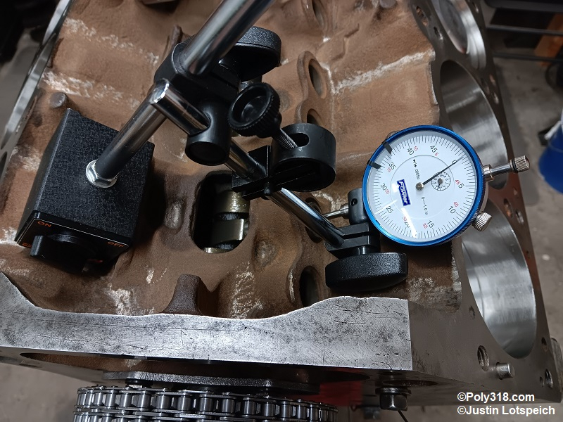
Install the dial indicator magnetic base in the lifter valley and the dial indicator positioned as if it were the push rod and parallel with the lifter (Figure 21a). Note that if the indicator is angled and not parallel with the lifter, the measurement will be inaccurate. Adjust the setup so that the dial indicator has plenty of room to travel down. Slowly rotate the crankshaft clockwise until the gauge stops moving at full lift, and zero the gauge (Figure 21b).
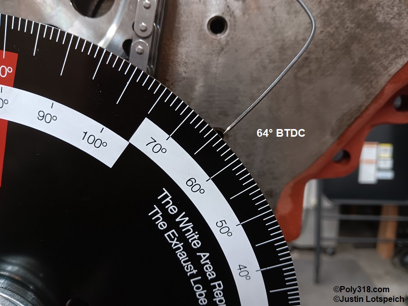
Using the prybar on the rear flange bolts, rotate the crank counterclockwise until the gauge reads 0.100”. Using the socket on the crankshaft, rotate the crankshaft clockwise to take out any slack in the timing chain until the gauge reads 0.050” BTDC. Write down the degree wheel number, which for my engine was 64° (Figure 21c).
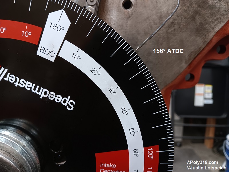
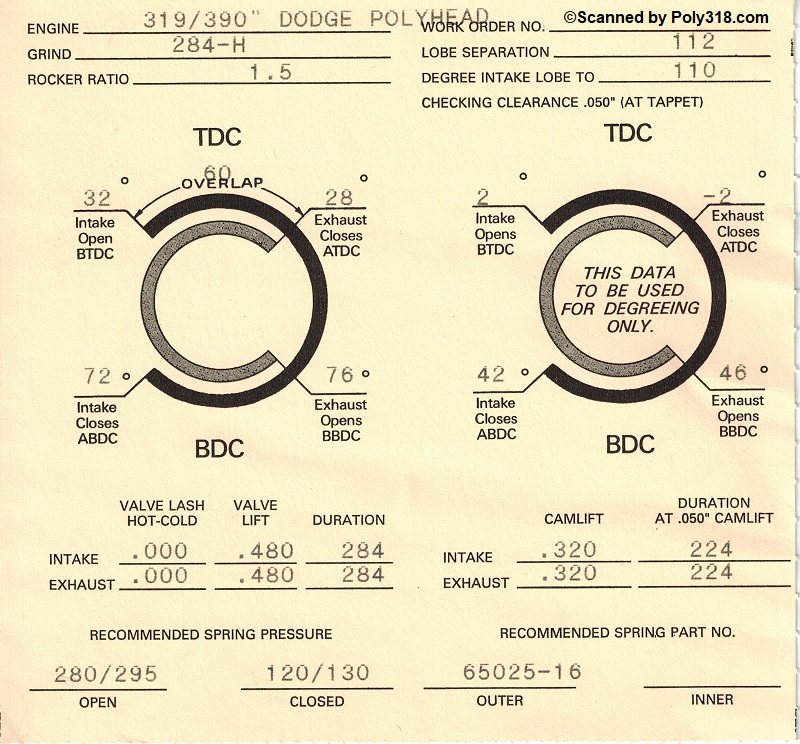
Rotate the crankshaft clockwise past 0.00” on the gauge to 0.050” ATDC, and write down the degree wheel number, which for my engine was 156° (Figure 21d). Add the two numbers and divide the sum by 2 to get the intake centerline, and compare it to the cam card supplied by the grinder/manufacturer, like Figure 21e for my camshaft. For my engine 64° BTDC + 156° ATDC = 220° / 2 = 110° centerline. The cam card specified degreeing the cam intake centerline to 110°, so I lucked out and didn’t need to make any adjustment and now knew my cam was properly degreed.
If the camshaft requires timing adjustment, use the front bolt to rotate the crank clockwise until piston #1 is firing on TDC with the cam lobes on their heels, remove the degreeing wheel, and remove the timing set by prying it off the cam and crank evenly. Rotate the crank sprocket as needed following the manufacturer instructions. Be extremely careful not to move the wire pointer at all or true TDC will need to be reset. I use a Cloyes 9-3503X9 billet roller timing set that allows for 4° of cam retard and advance, which makes cam timing very easy. After changing the camshaft timing accordingly, degree the cam again rather than trusting the sprocket stampings and machining are accurate. If the cam degree lands between the desired number, such as the cam card specifies 110° but you can only adjust to either 109° or 111°, adjust to the more advanced number (numerically lower) if you desire more horsepower at higher RPM or the more retarded number (numerically higher) if you desire more low-end torque, although one degree difference in cam advance likely won’t be felt in the seat on most builds. If the intake centerline is off by more than 4°, consult the camshaft and timing set manufacturers since there may be a manufacturing problem with one or both of the parts
For nonadjustable timing sets, you must use an offset woodruff key. Mopar used to make offset cam keys but discontinued them many years ago. Small-block Chevrolet crank keys made by Mr. Gasket fit the A/LA crank, and the 988G with 4° offset will provide about 4.5° offset, and the 987G 2° offset will provide about 2.25°., although other variables like the crankshaft keyway machining come into play.
With the camshaft degreed, remove the camshaft sprocket bolt, apply red thread locker to the threads, and torque the bolt to 35 lb.ft. Liberally lubricate the fuel-pump eccentric with assembly lubricant (Figure 21f).
Measuring Push Rod Length
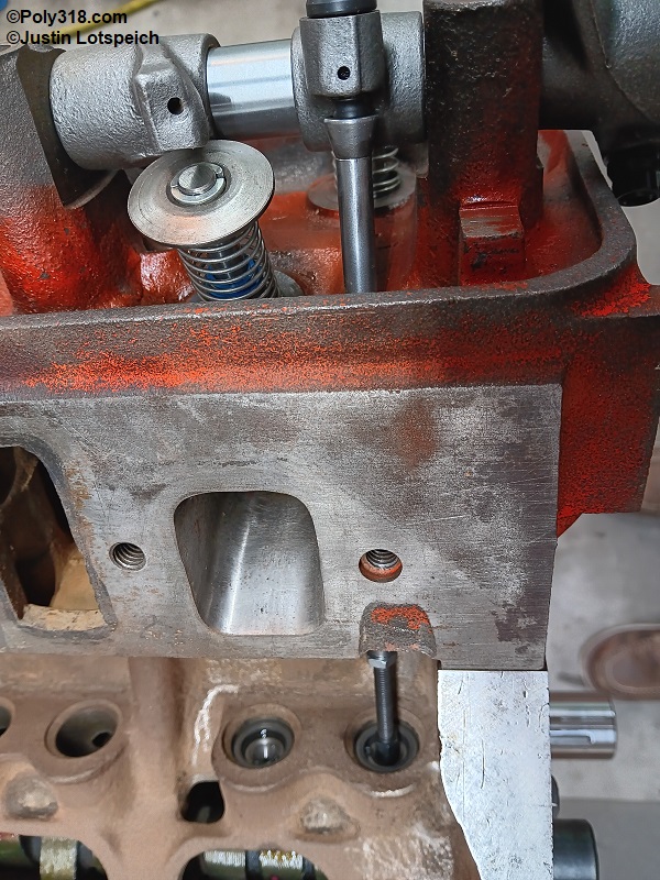
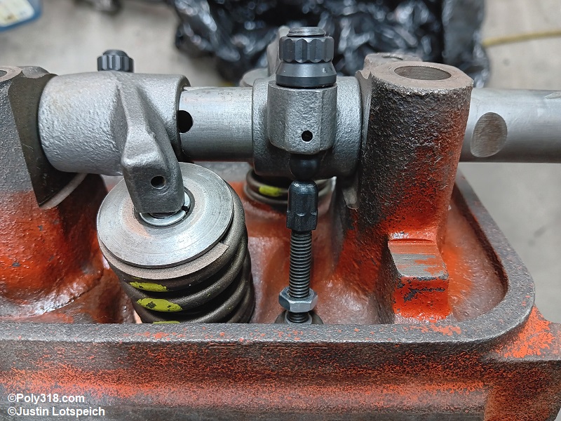
While the degree wheel is attached, it is time to measure needed push rod length, check valve-to-piston clearance, and inspect rocker-arm geometry. If not already done during cylinder-head assembly, remove the valve springs from cylinder #1 and replace them with soft test springs that are easily compressed by hand but strong enough to hold the valves firmly closed. Rotate the rocker arm adjuster screw to where it will be set at 0 lash with enough room to be turned in up to 1 turn to set preload (hydraulic lifters) or turned out up to 1 turn to set lash (solid lifters). Ensure that the adjuster screw is also positioned high enough into the arm to allow for proper oiling through the rocker arm to the push-rod cup.
Set the head on the engine block without the head gasket, and screw down the center bolt hand tight to hold the head in place. Using the crank front bolt, rotate the crankshaft clockwise until the intake lifter is on the lobe’s heel, all the way down in the bore.
Pull the rocker arm sideways out of the way, drop in an adjustable ball-cup push-rod checker, and lengthen it until it is tight against the lifter and rocker arm adjuster ball without slack but not compressing the lifter or valve (Figure 22a). Note that a ball-ball checker can be used, but care must be taken to keep the ball centered on the adjuster ball, which gets fussy when checking valve clearance and geometry compared to a ball-cup checker (Figure 22b). Slide the rocker arm out of the way, remove the push-rod checker, measure it with a caliper, and add the crushed head gasket thickness (you may need to contact the gasket manufacturer if the crushed spec is not available online). This sum is the required intake push-rod length for ordering. Pull the lifter and drop it into the exhaust bore, and repeat the process to measure the exhaust push rod length. For this engine, I ended up needing an 8.25” intake and 8.160” exhaust, so I ordered 8.20” push rods to have a matched set and used the adjusters to make up the difference.
Checking Valve Clearance and Rocker Arm Geometry
Reinstall the intake lifter and push-rod checker and adjust the push rod until the rocker arm is set at 0 lash without collapsing the lifter or valve. Position the dial indicator base on top of the head and the dial indicator on top of the valve retainer, parallel with the valve, far enough from the rocker arm to allow the arm to swing freely, and with plenty of gauge plunger movement down (Figure 23a). With the degree wheel at 0°/TDC, 0 out the gauge.
Slowly begin rotating the crank on the front bolt clockwise from 0°/TDC on the degree wheel to about 15° ATDC stopping every couple degrees to with the other hand push down on the rocker arm tip until the valve hits the piston. The goal is to rotate the crank and depress the rocker arm every couple degrees until you find the shortest length the valve travels down before hitting the piston. Warning: Generic instructions will tell you to check the intake valve at 10° ATDC, but that is not always an accurate position depending on the cam grind. For example, this engine had the tightest intake point at 5° ATDC. Once finding this tightest point, depress the rocker arm tip while reading the gauge, add the crushed head gasket thickness, and you have calculated the intake valve-to-piston clearance. My engine had plenty of intake clearance at 0.243” at 5° ATDC.
Before moving on to checking the exhaust valve, rotate the crank clockwise while watching the rocker arm and push rod move through their entire sweep. You are looking to confirm the rocker-arm foot is positioned securely on the valve stem tip and that the push rod maintains at least 0.050” clearance around the cylinder head throughout the sweep (Figure 23b). There is an ideal position and amount of rocker foot sweep that I don’t go into here because the A-block does not allow for adjusting this geometry like you can do on an LA with offset shims. The A-block rocker-shaft towers encircle the shaft and must be cut in half, machined into caps, and line bored to allow for such shimming adjustment. The adjustment will benefit extremely high-performance builds, but most builds will work with what they have. In general, the A-block rocker-arm foot will rest off center toward the intake manifold side with the valve closed (Figure 23c) and closer to the center when the valve is fully open (Figure 23d). However, this sweep will differ depending on the camshaft lift, valve height, and how much wear or machining has been done to the rocker-arm bore, rocker-arm foot, and rocker shaft. If the rocker foot at any point tries to slide off the valve stem or bind, there is a major geometry issue that needs to be addressed.
Swap the parts and dial indicator onto the exhaust valve, and repeat these steps for the exhaust valve clearance. Warning: again, most generic instructions say to measure the exhaust-valve clearance at 10° BTDC, but my engine had the tightest spot of 0.532” right on TDC. Refer to the valve, cam card, connecting rod, and piston manufacturers’ literature for the minimum clearance needed. A generally accepted rule for iron connecting rods is 0.080” minimum intake and 0.100” minimum exhaust, although my tightest spec literature called for 0.060” minimum intake, 0.120” minimum exhaust.
Rotate the crankshaft clockwise until the degree wheel and wire pointer are at TDC with cylinder #1 on the compression stroke. Remove the dial indicator setup, the push rod(s), the two lifters, and the degreeing wheel being careful not to turn the crankshaft at all since TDC will need to be reset if moved.
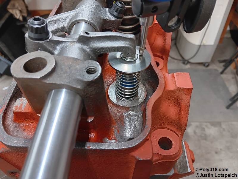
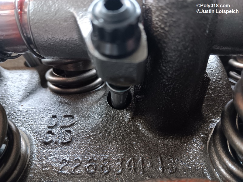
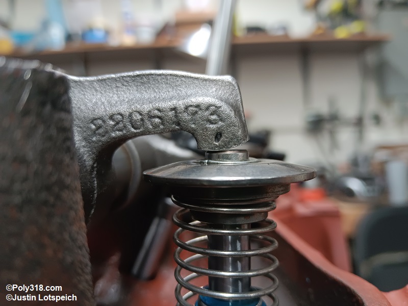
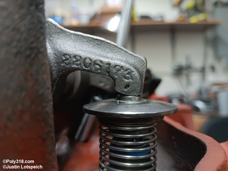
Lifter Installation
Apply a liberal coat of moly based assembly lube (I use Driven 00732) to the foot of each new lifter we already cleaned being careful not to get lube on the sides of the body (Figure 24a). Using a clean acid brush, apply assembly lube to the cylinder #1 camshaft lobes that we kept clean during blueprinting. One at a time, dip the lifters in a container of new conventional motor oil to coat the body, and gently set them into the block bore against the camshaft lobe (Figures 24b and 24c). Warning: Do not soak the lifter in oil over a long period of time or bench prime it. Do not use any type of assembly lube on the sides of the lifter body other than motor oil. The motor oil creates the least amount of resistance for the lifter to begin spinning immediately upon startup, which is crucial for proper flat-tappet camshaft and lifter break-in. Using thick assembly lube on the body makes the spinning action harder, which may lead to a flattened lifter and lobe within the first 30 seconds of running.
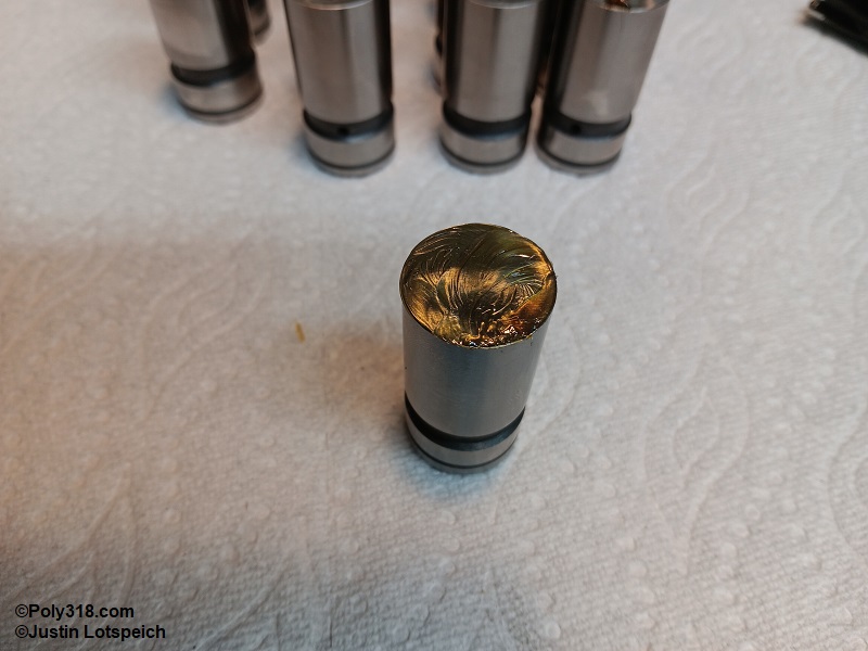
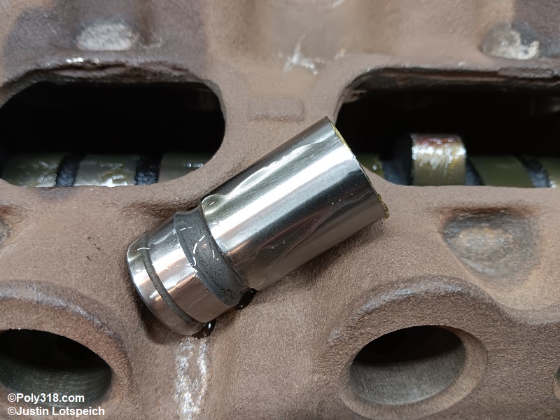
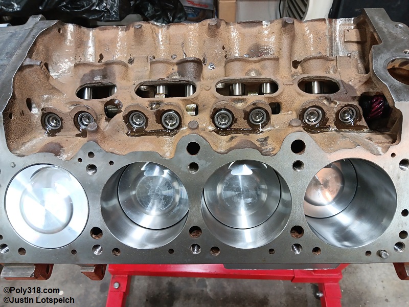
Cylinder Head Installation
Remove the cylinder head used for blueprinting, remove the two tester valve springs, and replace them with the proper springs (and spacers if equipped). Wipe off any oil on the block and cylinder head surfaces with lacquer thinner on a lint-free rag, and blow them off with compressed air. Blow off the new head gaskets with compressed air. Place the new head gaskets on the block paying close attention to any factory markings that distinguish an “up” side (Figure 25a). The A-block FelPro 7734PT I use should be installed dry with absolutely no sealant. If using a different type of gasket, follow the manufacturer’s instructions. For steel gaskets, I prefer using Permatex 80697 spray sealant.
Warning: Do not enlarge any coolant holes in the head gasket. I often come across online posts of people telling others to drill out the coolant holes with the mistaken reasoning that the block holes are much larger and the gasket holes should match but are incorrectly made (Figure 25b). The gasket holes are in fact correct and purposefully sized to meter the coolant flow from the block into the heads. Enlarging these holes increases the rate of flow through the block to where the heat transfer dynamics don’t have enough time, which results in higher cylinder temperatures and overall coolant temperatures. Using a high-flow water pump with enlarged gasket holes makes the overheating situation even worse.
Apply a 1/4″ diameter dab of ARP Ultra-torque to the threads of the cleaned head bolts, spreading it into the threads. Note: A-blocks have blind head bolt bosses that do not require sealing since they do not go into coolant; however, verify the bosses are blind in case of a casting error, and use RectorSeal T Plus 2 pipe sealant on any bolts that go through to coolant. Warning: Using too much Ultra-torque or sealant on the threads can result in it oozing out between the gasket, block, and head and may cause a leak, so keep the compound/sealant light.
Inspect each cylinder to ensure no debris is present. Hold the head square with the block deck, and carefully set it straight down over the alignment dowels. Install all the bolts finger tight, rotating the rocker-arm shaft as necessary to drop in the bolts. Using the sequence in the image, torque all the bolts to 30 lb.ft. and then to 60 lb.ft. (Figure 25c). Install the other head, and allow both heads to rest at 60 lb.ft. for at least twenty minutes to allow the gasket to settle before torquing them to the final 85 lb.ft. (refer to the gasket specifications if it requires a different torque amount).
If using the factory rocker arm shaft locking pin, apply a liberal amount of Loctite red threadlocker to the stamped wings, insert the pin into the tower, and drive it home with a clean ball-peen or brass hammer. If using a bolt after following my recommended method of drilling and tapping the hole for a 1/4″-20 Grade 8 bolt, apply red threadlocker to the bolt threads and torque to 108 in.lbs. (Figure 25d).
Coat both tips of the cleaned push rods with assembly lube, pull the rocker arms out of the way, and drop in the push rods. With the rocker feet pulled away, apply a liberal dab of assembly lube to the valve tips (Figure 25e). Position the rocker arms and push rods as they will rest. We will adjust the valves after painting the engine.
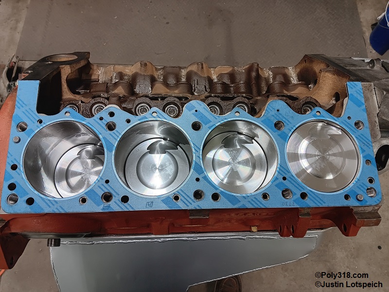
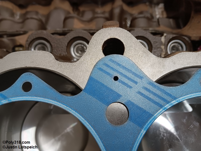
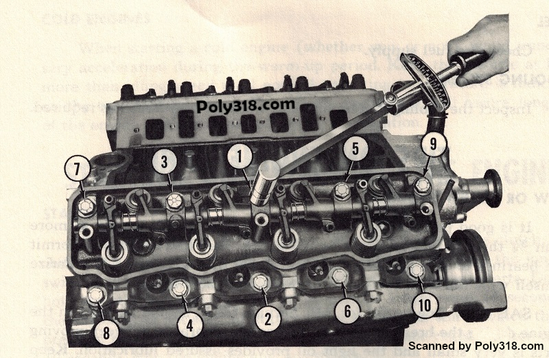
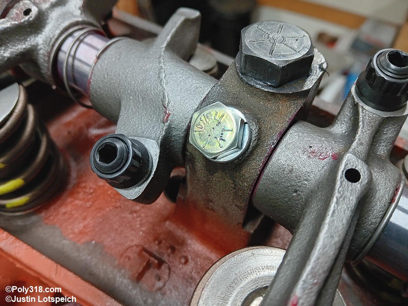
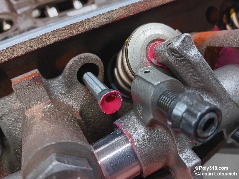
Timing Cover and Water Pump Installation
To prepare the timing cover, I use a die grinder and burr bit to remove the rough casting flash in the coolant passages to discourage blockage and oil drain-back locations to encourage quicker oil return (Figures 26a, 26b, 26c).
After cleaning the cover and and blowing it off with compressed air, wipe the damper seal well clean with a lint-free rag and lacquer thinner. Using a gloved finger, wipe a skim coat of quality RTV silicone around the insider wall of the well (Figure 26d). Using a bearing/seal driver, gently drive in the new seal with the open end facing the block, being very careful to start and drive the seal square and evenly until it bottoms out (Figure 26e). Coat the sealing lip with assembly lube (Figure 26f).
Using a lint-free rag and lacquer thinner, wipe off any oil from the block where the timing cover gasket rests. If equipped, install the oil slinger on the crank sprocket with the concave side facing forward toward the damper (Figure 26g). Apply a thin coat of motor oil or assembly lube to the crankshaft snout and woodruff key.
Warning: The A-block cast iron timing cover has two alignment holes drilled all the way through the cover that index on dowels pressed into the block. The aluminum timing covers do not have the alignment holes drilled all the way through. If using a cast iron timing cover, ensure that the block has dowels installed or there will be a direct hole through to the crankcase that will cause an oil leak and allow debris into the engine (Figure 26h).
Place the timing cover and pump paper gaskets on a piece of cardboard, brush Permatex 80019 gasket maker onto one side of the gaskets, and let them tack up until the liquid doesn’t transfer to a finger. Press the sealed side of the gaskets onto the cover and pump, brush the sealant onto the dry side of the gaskets, and let them tack up.
Only if using an LA 273/318/340 iron or aluminum cover on an A-block, an additional preparation step is required. The LA covers lack one of the A-block mounting holes that goes through to coolant that needs to be plugged in the block. An extra-long 3/8″-16 Allen setscrew (not a tapered pipe plug) can be used, or cut off a bolt’s threads 1/2″ long and use a cut-off wheel or hacksaw to cut a screwdriver slot into the head. Thread in the plug until it bottoms out, mark any portion that protrudes, remove the plug, and grind/file down any material. Wash the plug in lacquer thinner or brake clean and blow it dry. Coat the plug liberally with Permatex 80003 sealant or RTV silicone, tighten it until it seats snugly on the bottom of the boss, and smooth over the entire plug with sealant.
Install washers on the cover and pump bolts, and wrap the threads in Teflon tape and apply a liberal coat of RectorSeal T Plus 2 pipe sealant onto the yellow bolts in the image since they go through to coolant (Figure 26i). The red bolts can be blind bosses or can go through to oil, and apply RectorSeal T Plus 2 pipe sealant to them if they go through to oil to stop any future oil seeping.
After the gasket maker has tacked up, install the cover onto the block, over the alignment dowels, and carefully guiding the seal over the crankshaft snout so the sealing lip does not become damaged on the woodruff key. Use a bolt finger tight to hold the cover in place.
Install the water pump onto the cover remembering to include the accessories brackets and ignition timing pointer tab, if equipped, and tighten all the bolts finger tight.
Using a ratchet, torque the bolts in an “X” pattern to 15 lb.ft. and then again until the gaskets seat, which is around 35 lb.ft. for iron covers and 30 lb.ft. for aluminum covers but should be felt. After about 10 minutes, I check the bolts again since the pump gaskets usually crush and require tightening.
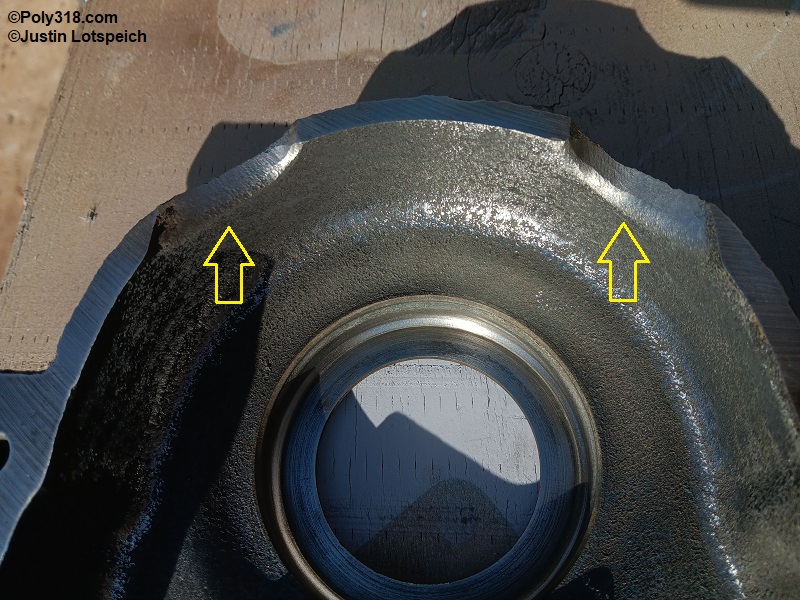
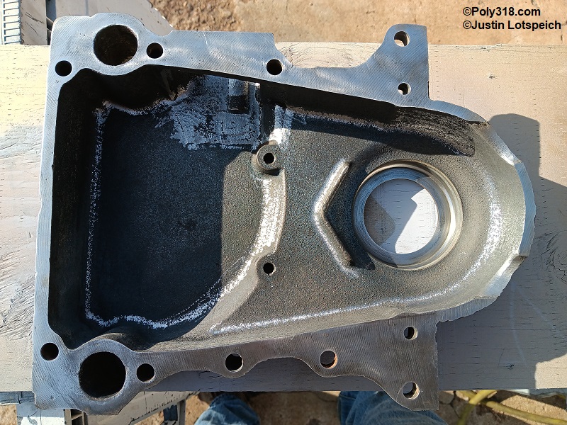
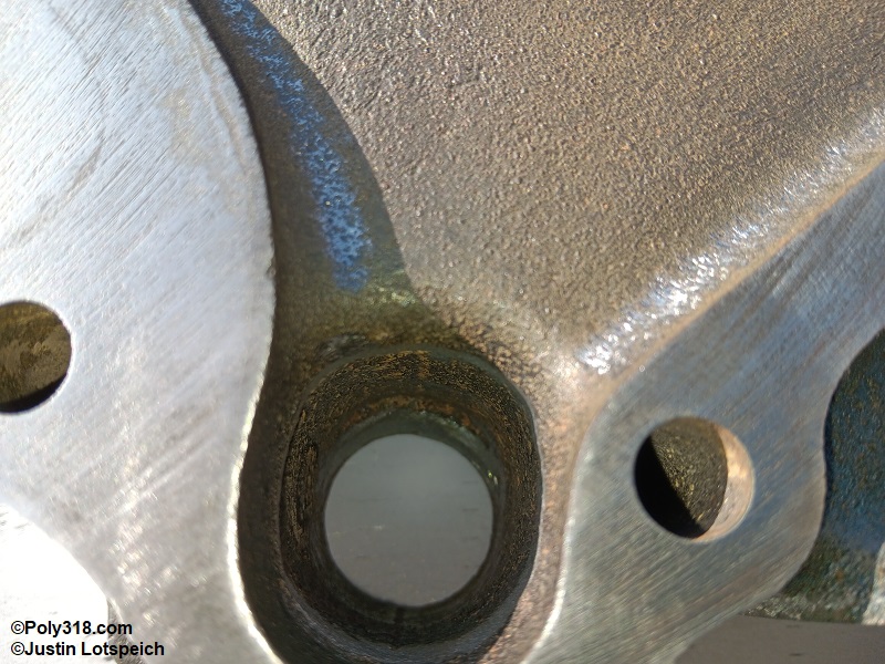
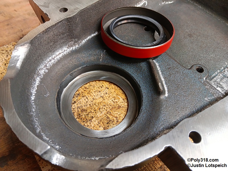
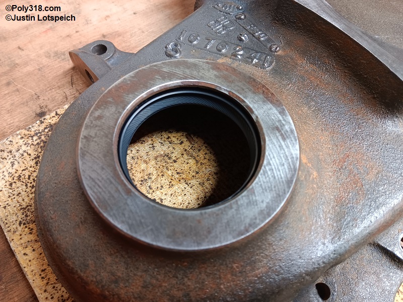
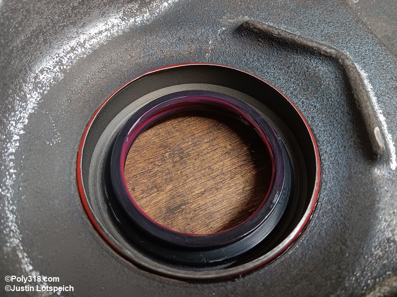
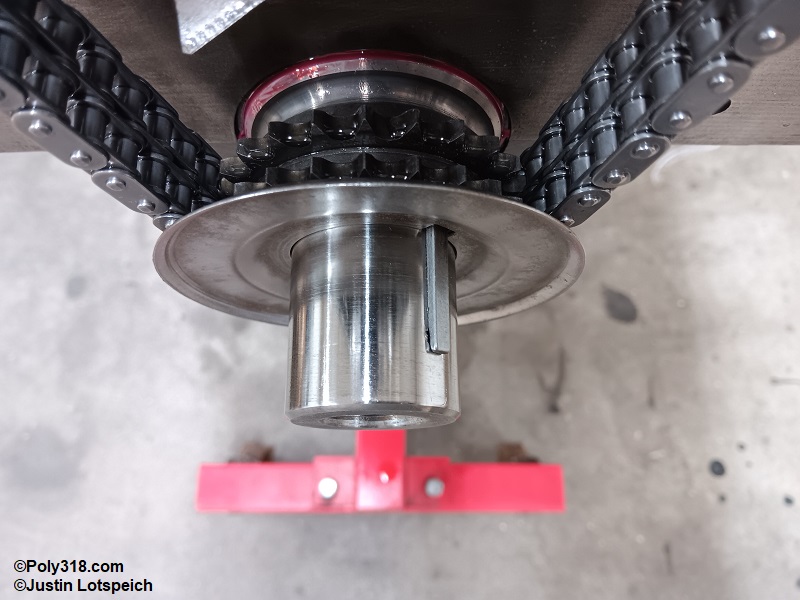
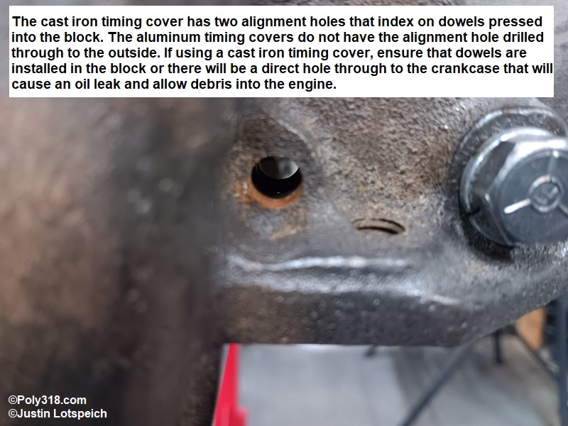
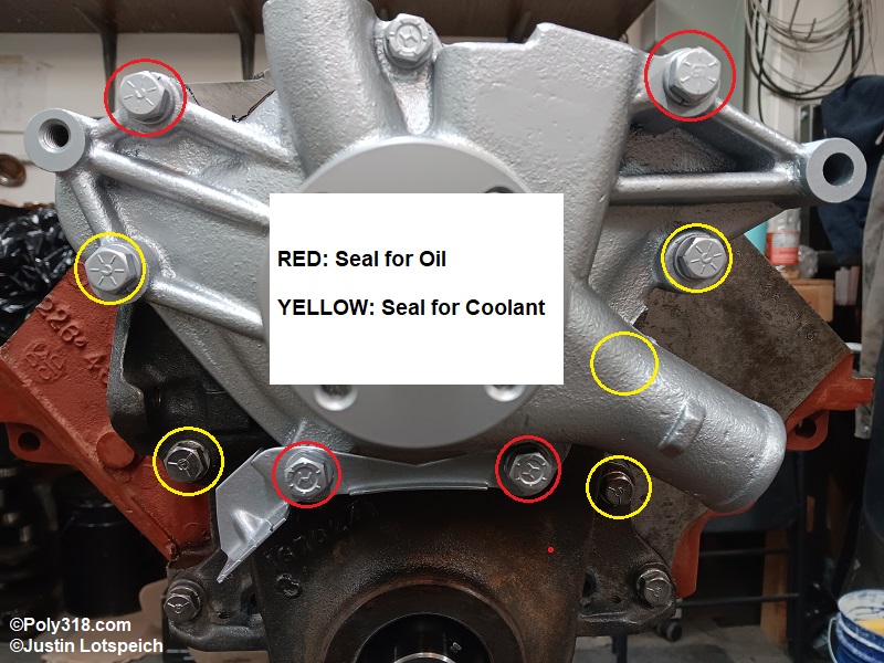
Exhaust Manifold Stud Installation
The bottom row of the A-block exhaust threaded bosses go through to coolant and must be sealed with a high-temperature compound. The studs should be cleaned of all oil with lacquer thinner for an optimal seal. Thread a nut down the exhaust manifold/header side of the threads until it hits the bulge, slide on a washer, and thread another nut down against the first nut. Apply RectorSeal T Plus 2 pipe sealant to the cylinder-head side threads, and thread the stud into the head (Figure 27a). Place a socket on the outside nut, and torque to 25 lb.ft. Use two wrenches to loosen and remove the nuts and washer without turning the stud, and wipe off any sealant that squeezed out (Figure 27b). If studs cannot be used on the bottom row like on some headers, I recommend sealing the bolt threads with RectorSeal T Plus 2 pipe sealant since it is made for high-temp steam and remains pliable for retightening the bolts.
The top row are blind holes. For studs, apply anti-seize to the threads that go into the heads, and install them in the same method as the bottom row. If using bolts, apply anti-seize.
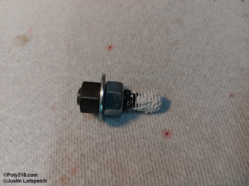
Oil Pump Installation and Pickup Clearance Adjustment
Before installing the oil pump pickup, place a straightedge down the oil pan rail along with bolt holes looking for any dimpled holes. If any dimples are present, place a socket extension and a 9/16” deep-well socket in the bench vise, position the pan bolt hole centered over the socket, and use a flat body hammer to carefully flatten the dimple. When finished, blow off the pan inside and out with compressed air.
Place the previously disassembled and cleaned oil pump in a bench vise. Apply Loctite red threadlocker to the threads of the cleaned oil-pump pickup, thread it into the pump, and use a pipe wrench about 1” away from the threads to tighten the pickup snug (approximately 30 lb.ft.) with the screen positioned to face the oil pan floor. Note: Setting clearance should be done quickly before the threadlocker sets up.
With the engine upside down, place a new oil-pump gasket and then the pump on the main cap (Figure 28a). Apply ARP Ultra-torque to the bolt threads and torque to 35 lb.ft. Place the new oil pan rail gasket dry on the block rails (do not install the rubber end seals on the pan).
Place a straightedge across the oil pan side to side, measure from that straight edge down to the inside pan floor, add the pan rail gasket thickness, and subtract 1/16” to account for gasket crush. This number will be where the factory pickup foot needs to be set off of the block pan rail. For example, if the pan depth from straight edge to floor is 10” and the gasket 1/8” for a sum of 10-1/8”, subtract 1/16” for gasket crush for a pickup height of 10-1/16” from the block rail to the bottom of the pickup screen. For aftermarket pickups with no built-in screen standoff, subtract 1/4″ – 3/8” from this pan and gasket sum to provide proper screen clearance. In our example, 10-1/16” minus 3/8” equals 9-11/16”.
You may have read somewhere to set the pickup 1/4″ – 3/8” off the floor of the pan, which is correct when talking about how far the screen should be off the floor. However, the factory A-block pickup has either a sheet-metal foot or a stamped cover that when tight against the pan floor places the screen 1/4″ off the floor. People who claim you must place the factory pickup 1/4″ – 3/8” off the floor are incorrect and are actually running clearances too wide at 1/2″ – 5/8”.
To adjust the pickup screen height, pull a measurement from the pan rail surface (use a straightedge across the block if necessary), and use a pipe wrench about 1” away from the pickup threads to rotate the pickup until the bottom of the pickup is at the appropriate height from the previous measurement. The pickup will not always be perfectly flat, so set it where no part is farther off the pan rail than the necessary measurement.
To confirm proper clearance, roll a 3/4″ diameter ball of soft plasteline clay or Play Do. Drape a piece of plastic wrap over the pickup at the point farthest from the pan rail, place the ball of clay on the plastic wrap, and fold the plastic wrap over the clay (Figure 28b).
Place the dry pan rail gaskets on the block rails (do not install the rubber end seals), and gently set the pan straight down onto the gaskets. Place pressure on the rails to force the pan down, but don’t press on the pan floor since it can oil-can and distort the clay measurement.
Lift off the pan and gently remove the clay (Figure 28c). Cut it in have with a sharp razor blade, and measure the thickness, which should be the intended clearance plus 1/16” since the gasket is not crushed (Figure 28d). For example, I set this engine’s custom pickup clearance at 3/8”, so the clay measured 7/16”, which will become a 3/8” gap once the gasket crushes.
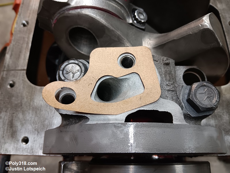
Oil Pan Installation
If the engine uses an aftermarket windage tray, ensure it is properly installed. For this engine, I built a windage tray into the pan when I built the pan (Figure 29a).
Inspect the pan rail where the timing cover mates, and use a razor blade to shave off any timing-cover gasket that protrudes being careful not to let any debris fall into the crankcase (Figure 29b).
Wipe all oil from the block pan rail, timing cover, and rear main cap sealing surfaces with a lint-free rag and lacquer thinner.
If the end seals secure to the pan, pull the rubber nubs through the pan holes with pliers to snap them into place. Apply a skim coat of RTV silicone (I use Mopar 4883971) into the gap between the end of the seals and the pan (Figure 29c).
Place the rail gaskets on a piece of cardboard, brush Permatex 80019 gasket maker onto one side of the gaskets, and let them tack up until the liquid doesn’t transfer to a finger (Figure 29d).
Push a 1/4” diameter bead of quality RTV silicone (I use Mopar 4883971) into the four corners where the pan rail meets the timing cover and rear main cap (Figure 29e and 29f). If the end seals don’t snap into the pan, gently push them into place onto the block and down into the silicone.
Carefully set the pan rail gaskets down with the sealed side against the block, and push them into the silicone beads (Figure 29g).
Wipe the corner silicone across the gaskets to fill any void where they meet the end seals (Figure 29h), and apply another 1/4″ bead of silicone over the gasket and seal joint at the four corners. Brush Permatex 80019 gasket maker onto the undressed side of the rail gaskets, and let them tack up for a couple minutes. Warning: Don’t use silicone or gasket-maker sealant on the rubber end seals aside from in the four corners since it will cause the seals to squeeze out of place and create leaks.
Carefully set the oil pan straight down aligning the bolt holes before allowing it to touch the gaskets/seals. Note: It is normal for the end seals to hold the pan high off the block. Install the larger corner bolts that have reinforcement in the pan rail, pressing down on the pan rails as necessary to start the bolts.
I use a 1/4″ ratchet with a long extension to better feel the gasket seating. Working from the front corner bolts and then to the rear corner bolts in multiple small turns, slowly and gently tighten the corner bolts to compress the end seals until you are able to start all 18 pan bolts. Warning: Do not use a heavy hand or you can warp the pan rail.
Working from the outside reinforced bolts in using the sequence shown in Figure 29i, slowly tighten the bolts in four stages relying more heavily on the reinforced corner bolts to crush the end seals since trying to pull down the pan from the center bolts will warp the rail. The first step should lightly tighten the bolts to even out the pan and begin seating the gaskets. Continue working the bolts until the final sequence and you feel the gasket seat when you feel slight solid resistance. Warning: Do not overtighten the bolts because the pan will dimple, squeeze out or even split the gasket, and may cause leaks. The factory torque spec is 180 lb.in., but this amount is usually too much especially for aftermarket pans with thinner gauge metal. I recommend torquing by feel until the gasket seats.
When finished torquing the bolts, inspect the end seals for uniform crush. Smooth any protruding silicone from the corners to fill any gasp between the end seals, rail gasket, and block (Figures 29j and 29k).
Install the clean drain plug/gasket and tighten until the gasket seats but no more than 25 lb.ft.
Install the cleaned dipstick tube into the block. If the fit is not snug, apply a skim coat of Loctite blue threadlocker to the tip. I use a cheap open-end wrench around the tube atop the seating bulge and strike the flat side of the wrench with a hammer near the tube to drive it down (Figure 29l). Note: A-block dipstick tubes are not reproduced, but an LA tube can be modified to work. The press-in portion of the LA tube is too wide, so use a belt sander or bench grinder to evenly sand/grind down the tube until it will start in the block hole but requires driving in, which is usually around 23/64” diameter. Clean and blow out the tube of all shavings before installing it.
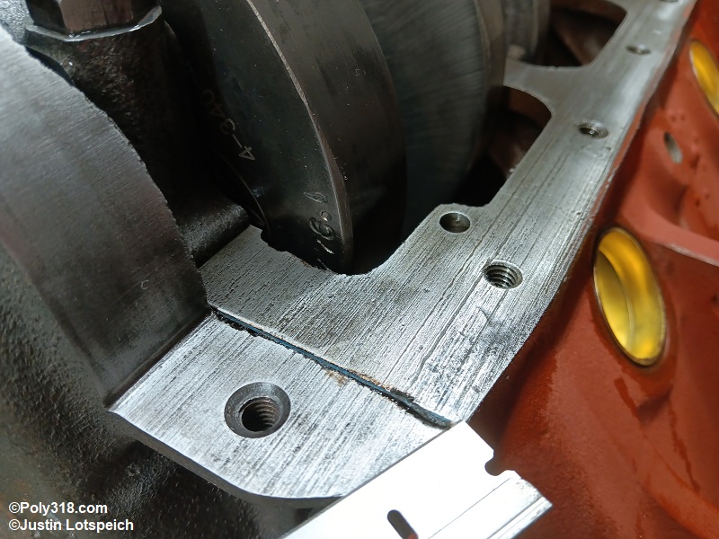
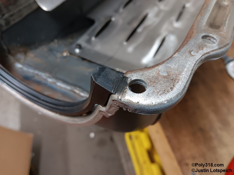
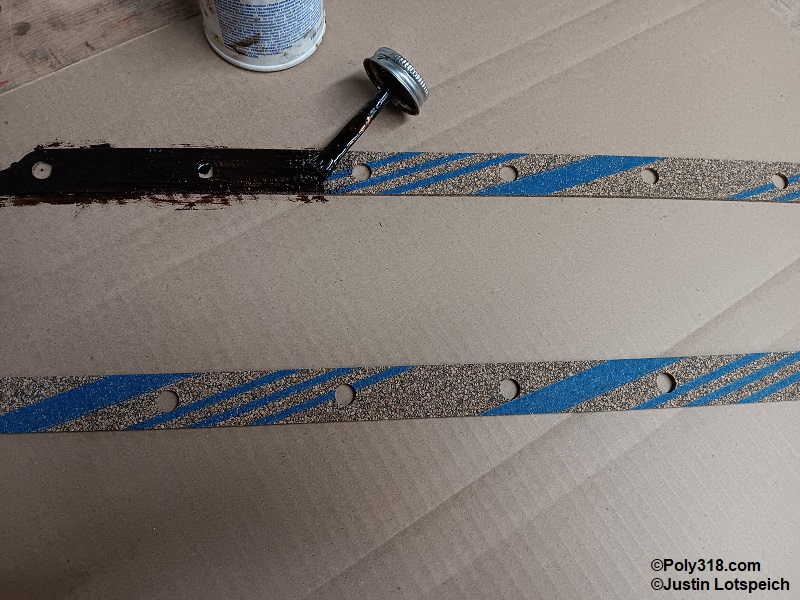
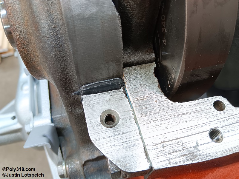
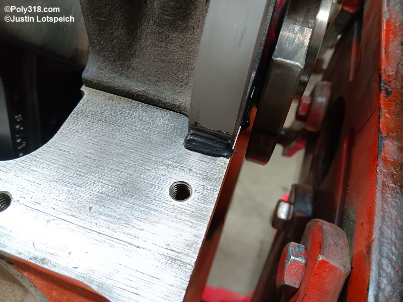
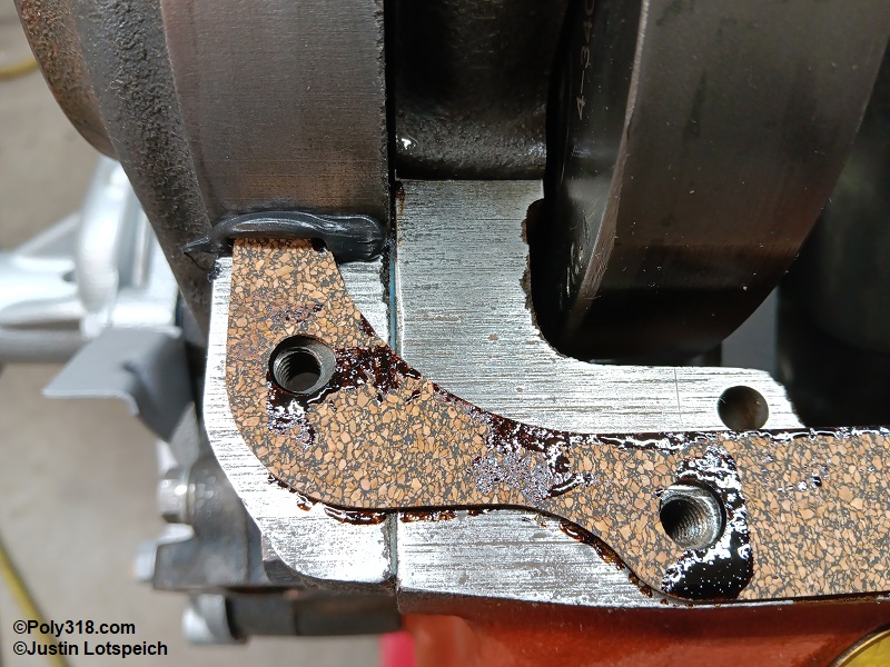
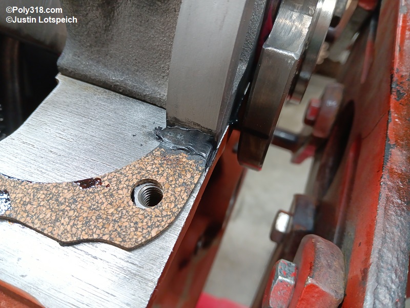
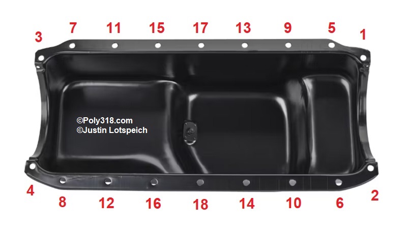
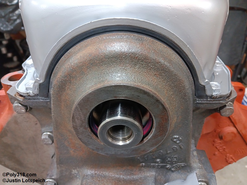
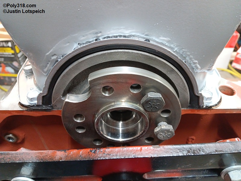
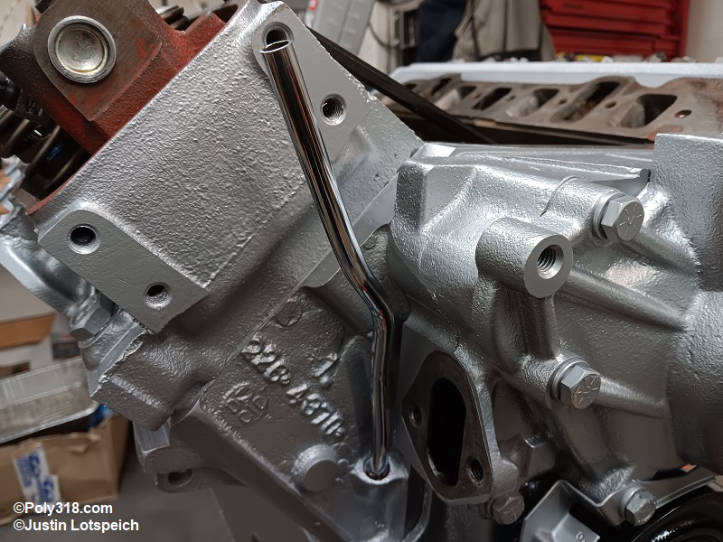
Painting
After all the sealants have been allowed to cure for at least 48 hours, prep for paint. All bolt-on components, such as the intake manifold, should be scrubbed with hot water and Dawn dish soap to remove all grease/oil and blown dry (Figure 30a). I paint the intake manifold off of the block to stop overspray from entering the lifter valley, so mask off the intake manifold (Figure 30b).
Working in a ventilated area wearing proper personal-protective equipment, use a small can filled with lacquer thinner and a clean solvent brush to wash any exterior parts that have come in contact with oil or assembly lubricant. Use the solvent brush in one hand and pat off the lacquer thinner with a clean cotton rag with the other hand before the solvent has time to run all over the place or into the distributor hole, lifter valley, intake ports, or exhaust ports. Warning: Don’t wipe the rough cast surfaces dry since it will leave lint, so pat those areas.
After the solvent evaporates, apply masking tape on the intake sealing surfaces, set down the cleaned intake manifold, and use a sharp razor blade to trace the intake manifold and trim the masking tape (Figure 30c).
Use masking tape and paper to mask off the lifter valley, cylinder heads, distributor hole, exhaust ports, oil-pressure port, and front crankshaft snout/seal (Figures 30d and 30e). Use a wire wheel to clean an old set of spark plugs, blow off all debris, and install them finger tight to seal the holes.
The last prep I do after masking is spray on a light coat of wax and grease remover and pat it dry with a clean cotton rag. Use a clean chip paint brush and light compressed air to blow the metal dry and to remove any lint being careful not to blow off any masking material.
Working in a well-ventilated area where overspray won’t harm anything, make a light fogging pass on the metal with high-temp engine enamel primer on the engine assembly and any bolt-on parts like the intake manifold hanging or on a table (I use Dupli-Color DE1612 primer). Let this light coat tack off, and shoot another slightly heavier but still light coat in a different direction pattern. After the second coat tacks off, shoot a heavier still fogging coat in yet another pattern being careful not to run the paint. Continue this process using different direction patterns until the metal is completely covered and you cannot see through the primer (Figures 30f, 30g, 30h). Spin the engine on the stand as necessary to prime the underside.
Allow the primer ample time to cure where a finger doesn’t stick to the primer on an area of masking tape before moving to the topcoat of high-temp engine enamel. For my engine going in my tutone jade metallic green amd seafoam green 1956 Dodge coupe, I chose the 1957 – 1958 Plymouth “Dual Fury V800” color combination of a silver engine and gold valve covers. I used Dupli-Color DE1650 “Cast Coat Aluminum,” which is very close to the original silver. Apply the topcoat in the procedure as the primer being careful not to run or pool the paint. Apply at least four thorough coats until obtaining full coverage (Figures 30i, 30j, 30k). Tip: Be very careful when applying metallic paint to not pool or run the paint since the metallics condense and show the blemishes much easier than solid colors. Using multiple lighter coats will stop running and help prevent fish-eye that may occur when applying coats too heavy.
Paint the valve covers, harmonic damper, pulleys, brackets, and any other components using the same prep and painting process as the engine assembly (Figure 30l).
Allow the paint to cure for at least 24 hours (longer in higher humidity and lower temperature) before removing the masking tape and spark plugs to stop flaking paint from the masking material from embedding in the topcoat paint. Carefully blow off the engine with compressed air to remove any flakes so they do not enter the engine.
A note on clear coat: In the past, I have experimented with shooting clear coat over the topcoat once it tacks off, which creates great depth. However, I have found that every manufacturer’s clear I have used turns amber after a few months of heat cycles and distorts the hue of the topcoat to where I don’t use clear. Blues will look greener, reds and yellows more orange, silver more gold, etc.
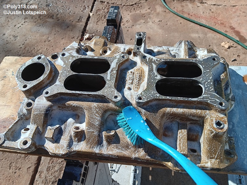
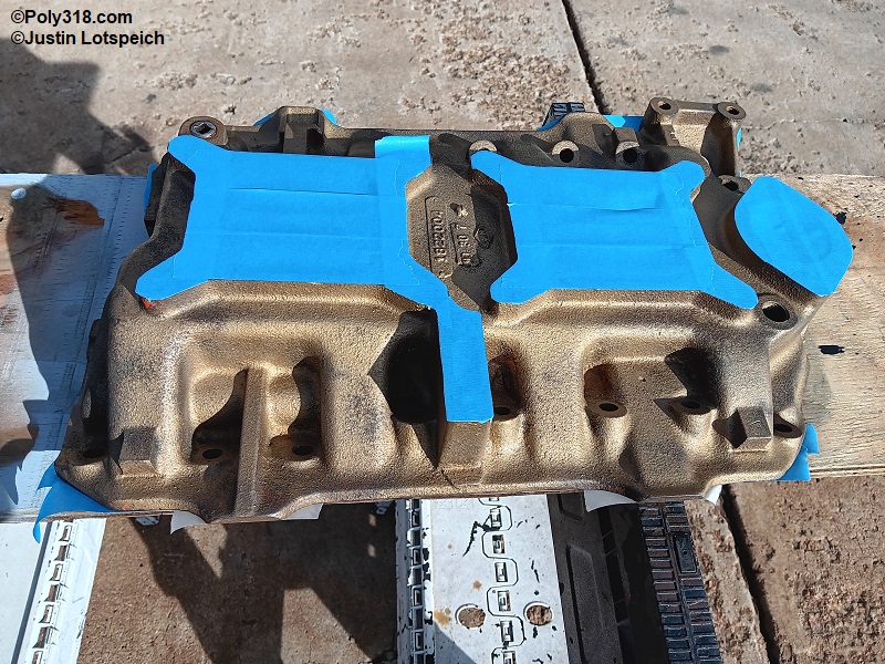
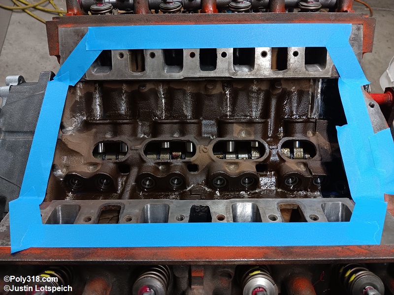
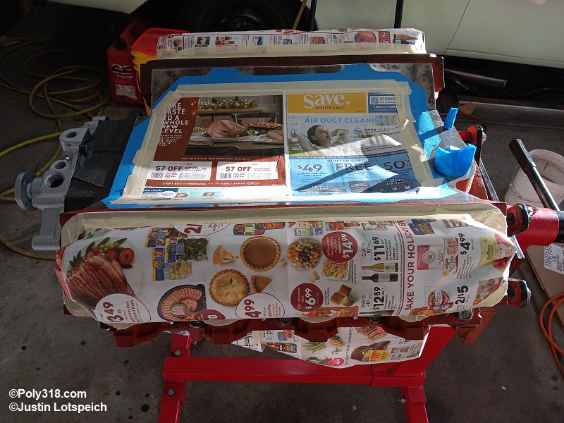
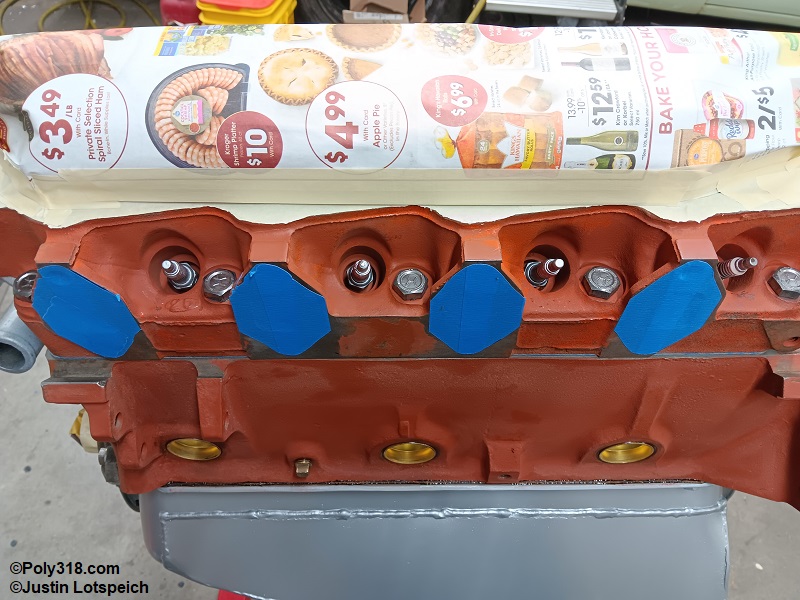
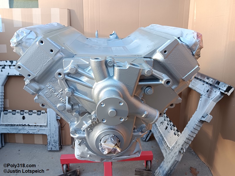
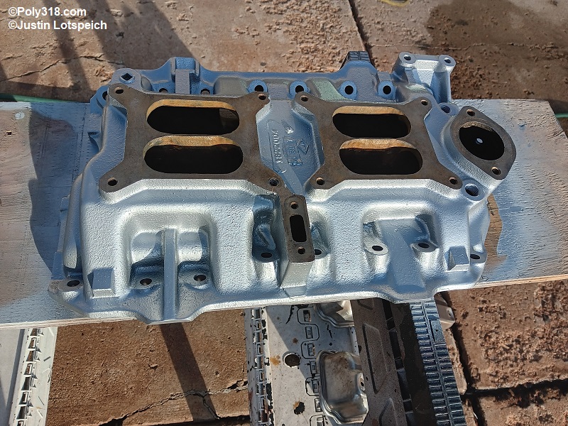
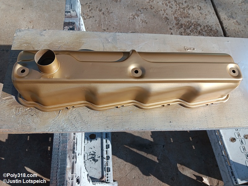
Harmonic Damper Installation and Timing Marker Alignment
If the gasket kit includes a large felt ring, install it over the damper hub into the sheet-metal well. This felt pad is not necessary but helps keep debris away from the seal. Coat the outside of the harmonic damper hub (or pulley hub for A-blocks without a damper) with assembly lube (Figure 31a). Coat the inside of the hub with assembly lube to assist with corrosion prevention. Start the damper onto the crankshaft snout and key, and gently start it with a rubber mallet hit in the center. Thread in a damper installation tool and press on the damper until it seats (Figure 31b). I sell an inexpensive installation tool on the website if you need one. Warning: Do not beat the damper onto the snout and then use the damper bolt to press it on since doing so can damage the damper rubber, the bolt threads, and the crank threads.
Warning: Some A/LA water pumps have the casting incorrectly too low to where the damper hits it. Before pressing on the damper, inspect the damper-to-pump clearance, and grind the pump as needed, as I had to do for this engine (Figure 31c).
Before installing the damper bolt, align the timing marker and damper mark at true top-dead center where you left the crankshaft after degreeing the cam. If the damper groove does not align at 0° on the marker tab, enlarge the tab holes to move the marker or use a file to carve a new groove in the damper (Figures 31d and 31e). Use a toothpick to brush white or another bright enamel into the groove for better visibility during timing.
Apply Loctite blue threadlocker to the damper bolt, slide on the washer, and torque the bolt to 135 lb.ft. while holding the rear crank flange bolts with a pry bar (Figure 31f). The crankshaft can now be rotated when needed since true TDC has been marked.
Note: If using a neutral-balanced LA damper with an A-block timing cover and marker, the groove will be on the left (driver) side. Use a file to create a new groove in the damper that aligns with the A-block marker at 0°.
Place a drop of Loctite blue thread locker onto the 5/16” crankshaft pulley bolts. Install the painted crank pulley onto the harmonic damper, tightening the bolts in a start pattern to 200 lb.in. (Figure 31g).
Install any brackets and the water pump pulley not already installed (Figure 31h) 3/8” bolts are torqued to 30 lb.ft. and 5/16” bolts to 25 lb.ft.
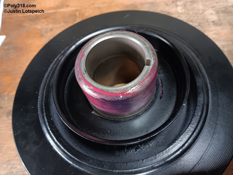
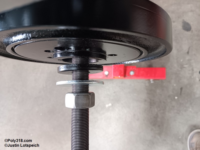
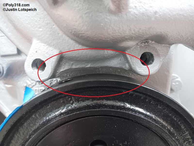
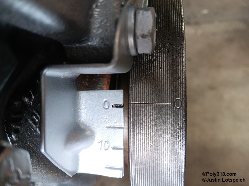
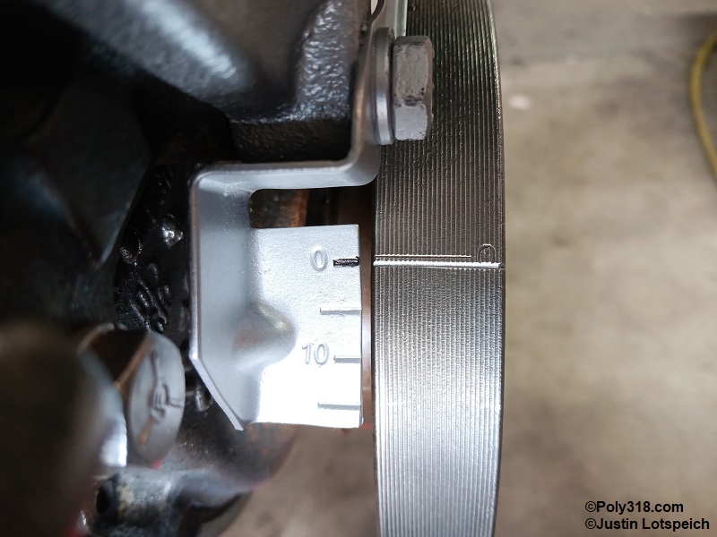
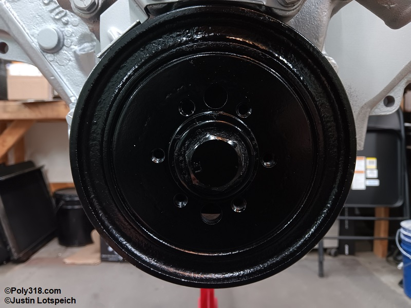
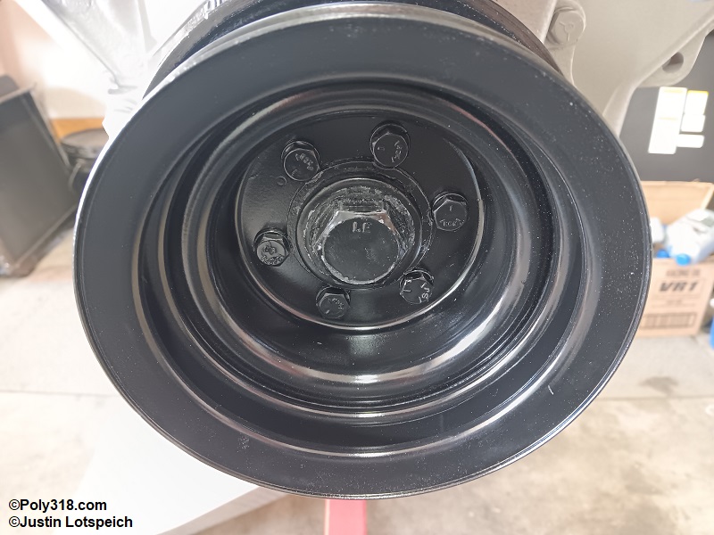
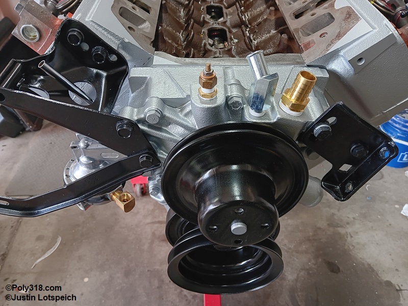
Valve Adjustment
We are ready for valve adjustment. Since the engine is on cylinder #1 compression TDC, we start there. For valve preload or lash, refer first to the camshaft grinder/manufacturer’s specification. If none exists, use the manual’s spec, which I provide next. Cold specs should be used during rebuilding and then the valves readjusted with the engine hot after camshaft break-in.
For most engines with hydraulic lifters, cold preload is 1/2 turn in and hot is 3/4 turn in. However, some variable-duration performance hydraulic lifters should be set using a feeler gauge like a mechanical lifter. For mechanical lifters, cold lash is typically 0.015” intake and 0.023” exhaust and hot lash is 0.013” intake and 0.021” exhaust.
Rotate the crankshaft clockwise until the #1 exhaust valve just starts to open, which guarantees the #1 intake valve is completely closed. Back off the adjuster screw to where you can jostle the push rod. Hold the push rod between two fingers and spin it back and forth while slowly turning in the adjuster until you feel the slightest drag on the push rod but without collapsing the lifter (hydraulic lifters) or collapsing the valve (solid lifters). This point is called zero lash (Figure 32a).
For hydraulic lifters that use preload, turn the adjuster in another 1/2 turn to set cold preload. If using a jam nut, hold the adjuster with the Allen wrench and snug down the jam nut with a closed-end wrench to approximately 25 lb.ft. ensuring the adjuster doesn’t turn (Figure 32b).
For solid lifters, use a “go-no-go” method with an exact feeler gauge and a feeler gauge the next size up, such as a 0.015” exact gauge and a 0.016” too-large gauge. After setting zero lash as described above, slowly back off the adjuster until you can slide the exact size gauge in and out feeling drag between the rocker arm and valve tips (for roller rocker arms, move the gauge side to side across the roller tip). Switch to the larger gauge and try to insert it. If you cannot fit the larger gauge, the lash is properly set. If you can fit the larger gauge, turn in the adjuster until the exact gauge goes in but the larger gauge does not. If using a jam nut, hold the adjuster screw and snug the jam nut to approximately 25 lb.ft.
Move on down the firing order of 18436572 with cylinder #8 next. Rotate the crank clockwise until the #8 exhaust valve just starts to open, and adjust the #8 intake valve. Continue down the firing order until all intake valves are adjusted.
Once all the intake valves are adjusted, turn to the exhaust valves. For adjusting exhaust. Start at cylinder #1, and rotate the crank clockwise until the intake valve fully opens and just starts to close. This position guarantees the #1 exhaust valve is fully closed. Adjust the exhaust valve using the same preload or lash method described previously using the proper amount of preload or lash. Move down the firing order adjusting the remaining exhaust valves (Figure 32c).
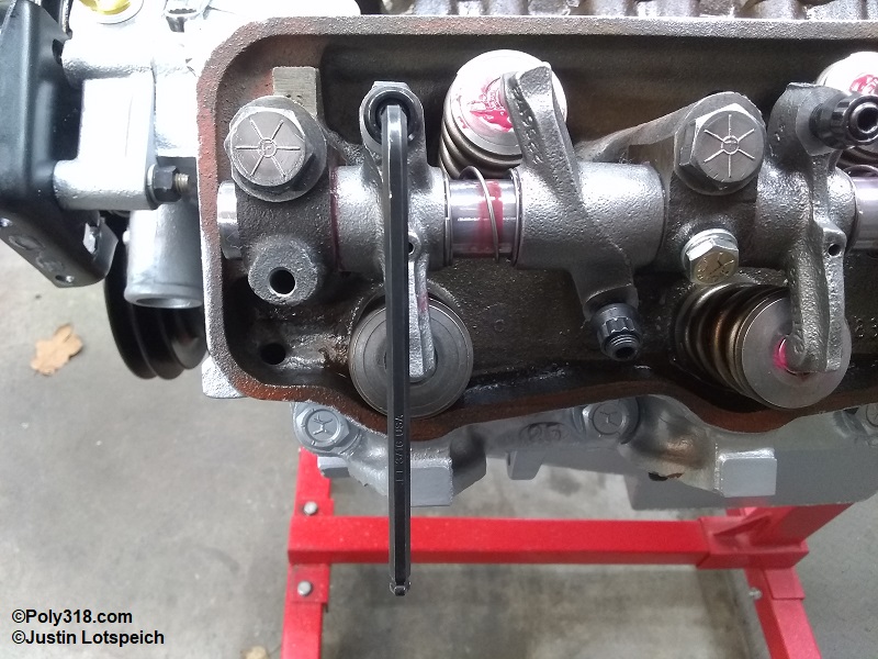
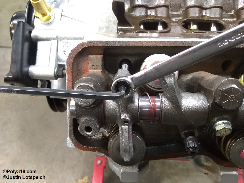
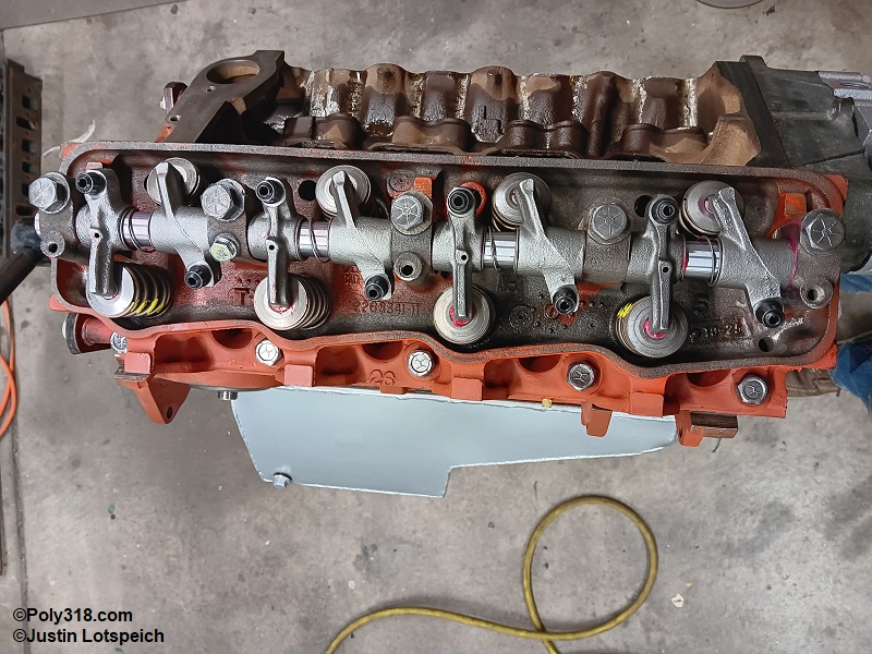
Oil Priming
The purpose of priming the oiling system of a rebuilt engine or one that has sat for a long time is to fill the pump, filter, galleries, lifters, and rocker-arm shafts with oil to both confirm the system is functioning properly and to supply immediate lubrication to the components upon starting the engine.
The cleanest method of oil priming is to cut the flat tops off a pair of valve covers, clean them thoroughly, and temporarily bolt them onto the heads with cork gaskets to keep the priming oil from overflowing down the engine block. If not using modified valve covers, keep a pan under the engine during priming since oil will overflow from the cylinder heads. For the purpose of taking photos for this article, I leave the valve covers off.
Using new motor oil, lubricate with the seal of a new quality oil filter that will be used for break-in (I use a WIX 51515 unless the headers require a shorter filter), and tighten the filter per the instructions (typically 3/4 turns past contact with the block).
Pour the appropriate volume of quality conventional high-ZDDP formulated oil down the distributor hole until the dipstick reads full, and then pour in the filter’s volume (Figure 33a). I use Valvoline VR1 10W30 formulated for flat-tappet lifters. Do not pour oil into the lifter valley or over the camshaft since it will wash away assembly lube. Warning: Never use synthetic or synthetic blend oil for piston ring break-in because it negatively impacts the seating. Also, never use an oil formulated with low ZDDP, including diesel oil, with flat-tappet lifters since it lacks sufficient ZDDP to protect the cam lobes and lifter feet.
Hook up a mechanical oil-pressure gauge with a range up to at least 65 psi to the rear oil gallery port adjacent to the distributor hole, and secure the gauge where it is easily viewable. Insert an oil-pump priming rod down the distributor hole into the oil pump rotor. 1956 – 1961 M51 pumps use a slotted tool, whereas 1962 onward M72 pumps use a hex tool.
Away from the assembly area, blow off/out a variable-speed, high-torque 1/2″ drive corded drill with a side handle to remove all dust/debris. Attached the drill to the priming tool, and begin spinning clockwise while watching the gauge for pressure, which can take a few seconds (Figure 33b). At full drill rpm, the gauge should read between 55 – 70 psi for cold oil depending on the drill rpm and type of spring used in the pump (Figure 33c). Inspect the top of the lifters, which should all have oil seeping up into the valley.
Note that the cylinder heads oil intermittently once per camshaft rotation when the camshaft galleries align with the block galleries. While spinning the drill, rotate the crank with the front bolt to approximately 22° ATDC with intake opening on #1 to send oil to the right (passenger) head, which is 1-1/8” to the left of the damper’s 0°/TDC mark when facing it. Spin the drill while inspecting the rocker shaft towers and rocker arms where oil should begin pouring out (Figure 33d). Note that rocker-arm oiling is accomplished with help of the arms rotating on the shaft as the valves open and close, so it is normal to not see oil pouring out of every rocker-arm hole. However, there should be some form of oil exiting orifices the length of the rocker shaft.
After you observe oil to the right head, rotate the crank to approximately 136° ATDC with exhaust opening on #1 to send oil to the left head, which is 9-1/4” to the left of the damper 0°/TDC mark when looking at it. Once you observe oil in the left head, remove the drill, priming tool, and gauge. Wipe off any oil from the outside of the engine with paper towels.
In preparation for firing the engine for camshaft break-in, rotate the crank until the damper timing line is at 30° BTDC (Figure 33e). Yes, while 30° of initial advance sounds insanely high, the engine will fire easier, and vacuum advance will not be used during cam break-in to where even with 22° of mechanical advance the engine will run between 2,000 and 3,000 RPM at a safe 52° total advance for an engine with no load on it. Since the factory timing tab does not have a mark for 30°, I’ve done the math for you. On a 7.25” diameter damper, every 5/16” of circumference equals 5°. Using a thin, flexible tire tape measure or tailor’s measuring tape, pull 1-7/8” clockwise from the damper timing line and mark the damper with a pencil or grease pen. Rotate the crank counterclockwise from 0° TDC firing on cylinder #1 where the pencil mark and timing marker align, confirming that the #1 intake valve has just closed. The engine is now set at 30° advance.
Inspect the oil pump/distributor intermediate drive shaft and gear for abnormal wear. File smooth any burs on the gear, and replace the part if the gear is worn excessively. Liberally apply assembly lubricant to the cleaned intermediate shaft and gear including there the gear rides on the block bushing (Figure 33f). Gently lower the shaft through the distributor hole and bushing. Use a long screwdriver to rotate the shaft clockwise where the gear teeth rise and fall to align the distributor slot as desired (Figure 33g). Position the slot parallel with the crankshaft for the distributor clocking in the factory location for the vacuum-advance canister and the #1 sparkplug on the cap. If a different distributor clocking is desired for canister clearance or plug wire routing, the slot may be positioned at any degree. Tip: If the drive shaft will not go down into the cam gear fully, the oil pump rotor is likely not aligned. Remove the drive shaft, insert the priming tool, and rotate the pump 1/8-turn and try to insert the drive shaft again, repeating as necessary until it seats.
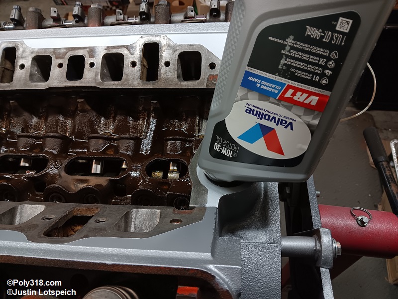
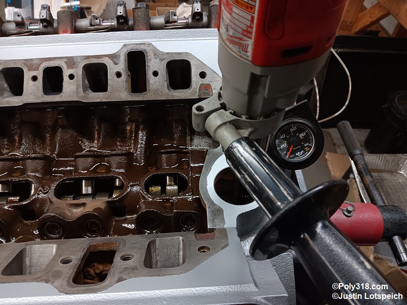
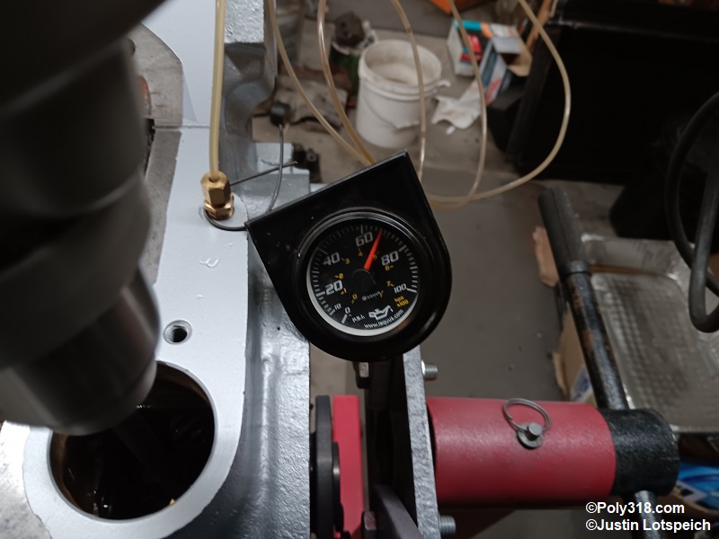
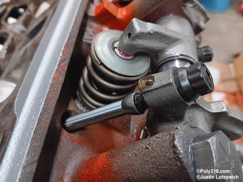
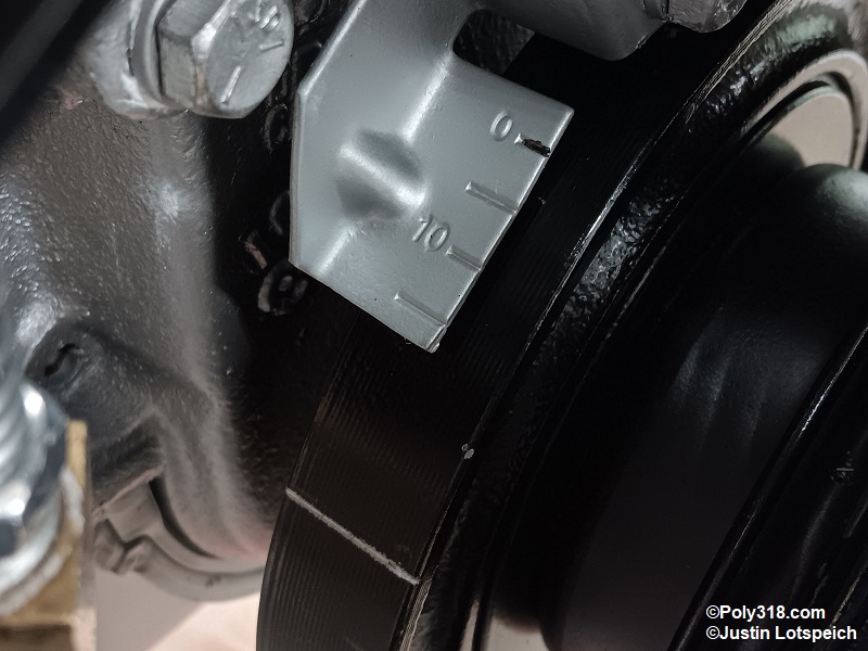
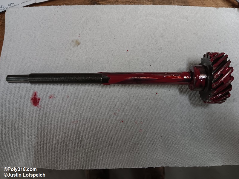
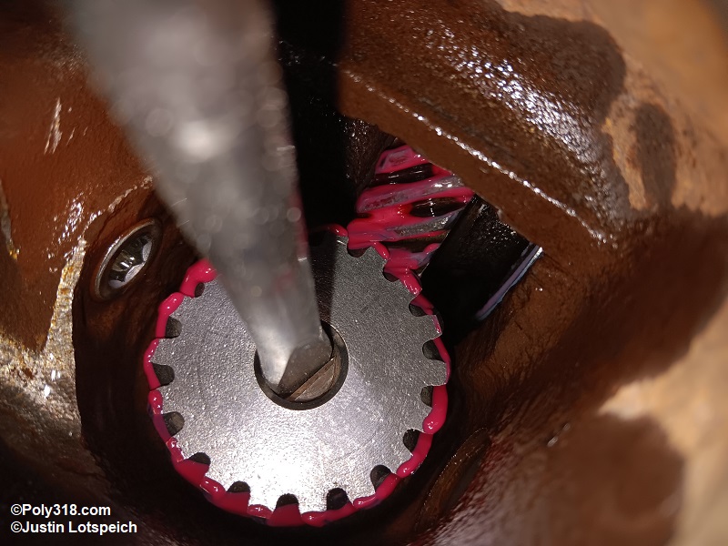
Intake Manifold Installation
To begin, check the end-rail gap by first setting the intake manifold down without a gasket. Lift one side of the intake, slip in a Best Gasket fiber gasket (the steel gaskets often leak), and do the same for the other side. Measure the gap between the block and the intake at the front and rear rails (Figure 34a). If the gap is more than 1/4” with the intake not torqued down, cut end-rail gaskets out of a 3/16” thick sheet of fiber or cork gasket using the intake manifold as a template. If the gap is 1/4” or less, like on this engine, RTV silicone will be used. Lift off the intake manifold and gaskets. Warning: Do not use the foam end gaskets that come with most kits because they easily squeeze and blow out causing leaks.
Using a clean lint-free rag and lacquer thinner, clean the head, block end rails, and intake surfaces to remove all oil from priming. Pay careful attention to clean out the crevice where the heads and block meet, and blow out these areas with air to remove any oil since they are the primary culprit locations for oil leaks.
Focusing on one head at a time working quickly to not allow the silicone to skin over, squeeze and thin 1/32” thick x 1/4″ wide line of quality RTV silicone (I use Mopar 4883971) around the head water jacket, head intake ports, and head exhaust crossover port. Use a gloved finger to spread the silicone evenly, and keep the silicone back about 1/8” from the openings when possible to allow room for the sealant to squeeze out without entering the runners (Figures 34b).
Squeeze a 1/4” bead of silicone into the two corners where the head and block meet pushing it into the crevice and leaving a 1/4″ protruding (Figures 34c).
Align the fiber gasket at the two bottom corners, push it into the beads of silicone. While swinging the gasket up, align the it with the runners, and gently press the gasket into the silicone on the head. Repeat the process for the other head (Figure 34d).
Smear silicone into all four corners where the gaskets meet the block end rails ensuring all gaps are filled. If not using fiber/cork end-rail gaskets, lay down a 1/4″ diameter bead of silicone on the block end rails making sure to press the silicone well into each of the corners overlapping the intake gaskets (Figures 34e and 34f).
If using fiber end-rail gasket, coat the block rails with a skim coat of silicone making sure to squeeze into the corners overlapping the side gaskets, and gently press the gaskets onto the rails. Then run a 1/4″ bead of silicone across the top of the fiber/cork end-rail gaskets making sure to overlap onto the intake gaskets.
Working quickly with the intake manifold upside down on the workbench with the sealing surface clean of all oil, place a 1/32” thick x 14” wide bead of silicone around the water jacket, exhaust crossover port, intake ports, and on the end rails in the same way as the heads. (Figures 34g and 34h). If used, install the exhaust crossover block-off plates into the silicone, and apply another bead of silicone over their perimeter to lock them in (Figure 34i).
Holding the intake manifold by the plenum, position it directly over the lifter valley and slowly lower it straight down into place aligning the bolt holes as best as possible before making contact with the gaskets. For a heavy cast-iron A-block intake, two people is helpful here.
No intake bolts go through to coolant on an A-block or LA. Some are blind holes, and others go through to the lifter valley where there is potential of oil seeping up the threads and pooling atop the intake. Apply RectorSeal T Plus 2 sealant to the bolt threads open to the valley to stop oil seepage. Warning: Ensure the bolts are the proper length since bolts too long can run into some of the push rods and cause binding, bending, or brakeage.
Start all bolts by hand and tighten using the sequence in Figure 34j in three steps of all bolts to 10, then 20, and finally 30 lb.ft. for a cast-iron manifold (25 lb.ft. for aluminum) until the gaskets seat firmly (Figure 34k).
I smooth the front end-rail silicone flat for aesthetics, but don’t undercut it. Alternatively, the silicone squeezed out can be cut flat with a razor blade after it fully cures. Allow the silicone to cure for at least 72 hours (longer in higher humidity or lower temperatures) with the water jackets empty to promote curing since the thick end-rail beads take long to cure and silicone cures via oxygen. Warning: Rushing to start the engine too soon can blow out the silicone end rail seals.
Wipe off the thermostat pad on the intake and cleaned thermostat housing with lacquer thinner. Apply a skim coat of silicone on the intake (Figure 34l). Set the new quality thermostat into the housing where the spring will face the intake (Figure 34m). Warning: Installing the thermostat upside down with the spring up in the housing will cause improper cooling). Apply a skim coat of silicone onto the housing sealing surface (Figure 34n). Gently press the fiber gasket into the sealant on the housing (Figure 34o). Apply a skim coat of silicone onto the thermostat housing surface, and set the housing straight down onto the manifold that is already coated with silicone. Since the bolts go through to coolant, apply RectorSeal T Plus 2 sealant to the bolt threads to stop seepage under pressure. Tighten the bolts until the gasket seats, which is usually around 15 – 20 lb.ft. (Figure 34p).
Install any sensors or fitting for oil-pressure and coolant temperature; the heater and water-pump bypass nipples; any coolant and vacuum plugs; and carburetor studs. Apply Teflon tape to all the oil and coolant threads (Figure 34q). Apply anti-seize to the carburetor stud threads going into the intake manifold to make future removal easy.
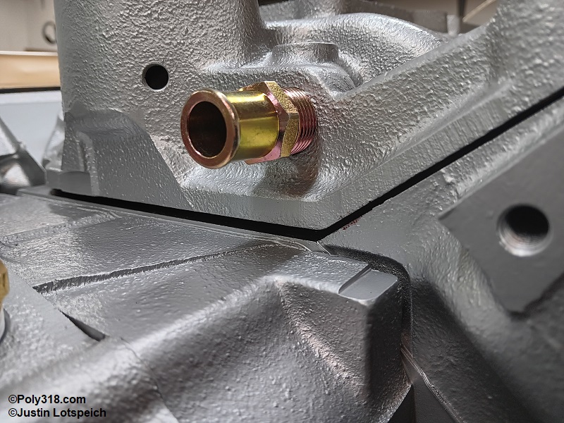
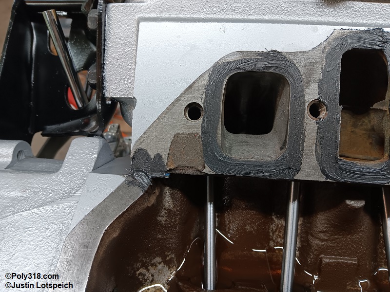
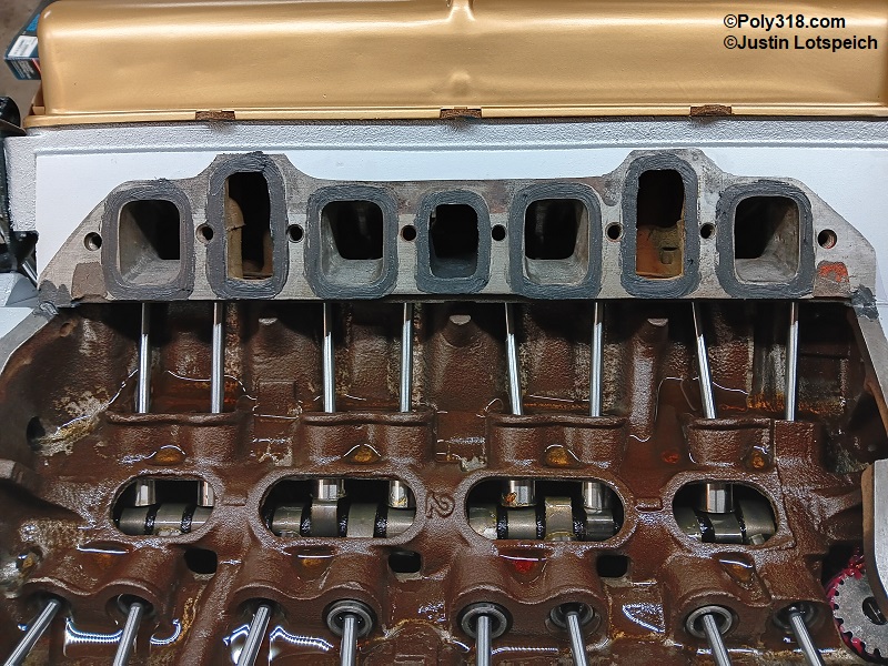
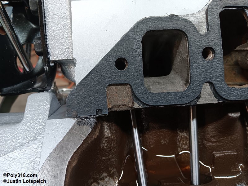
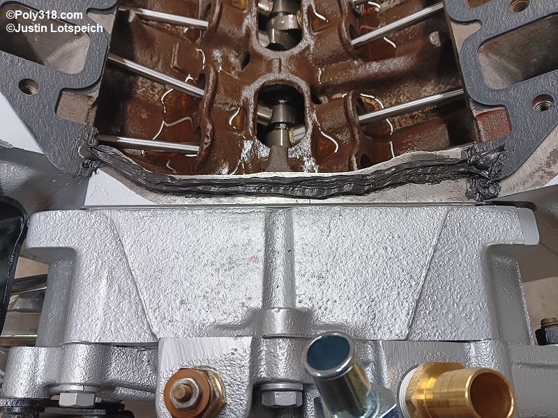
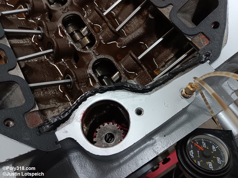
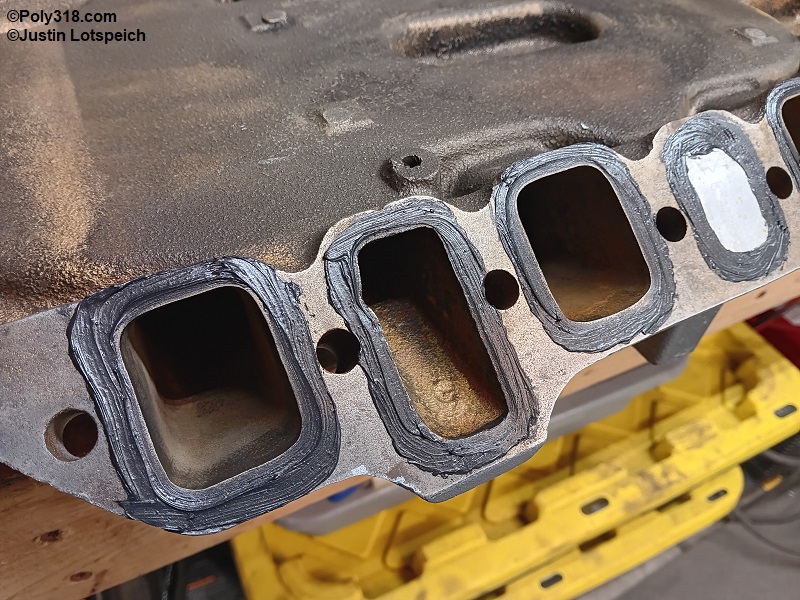
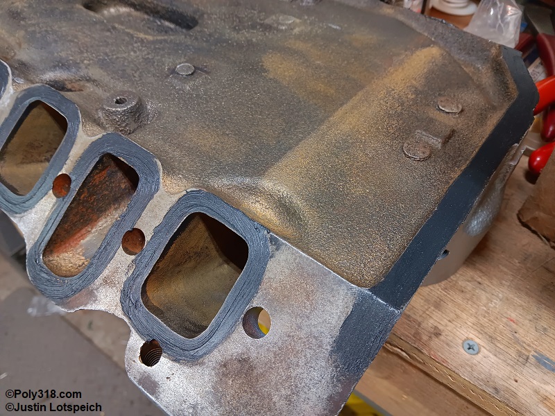
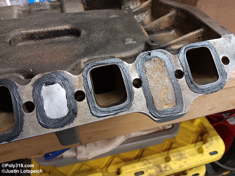
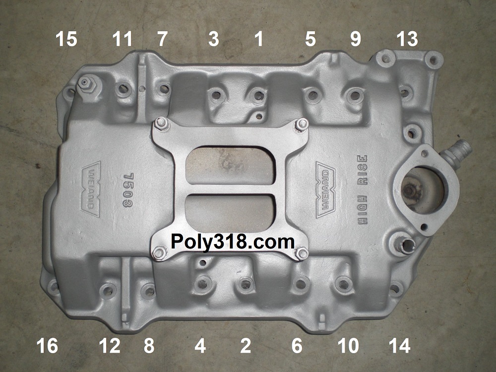
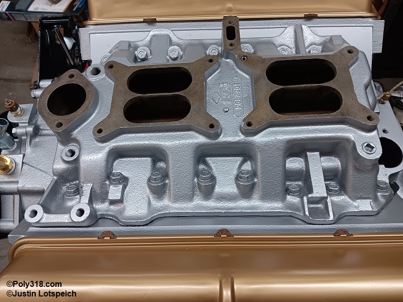
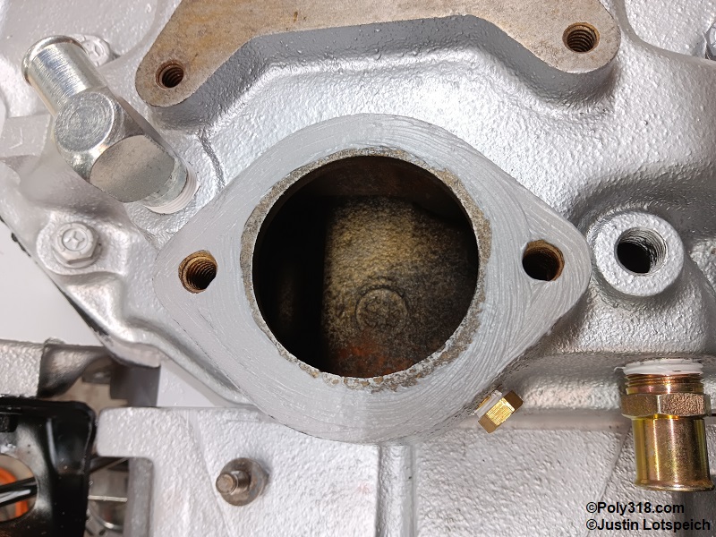
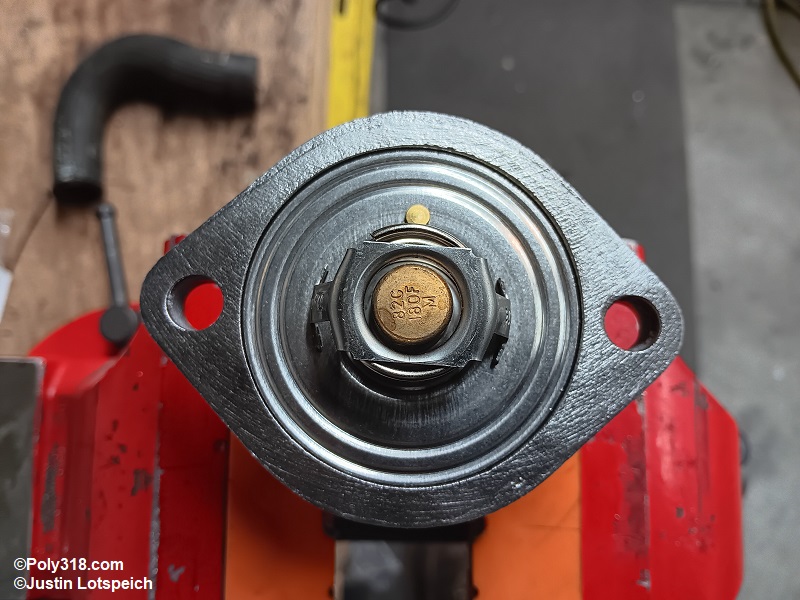
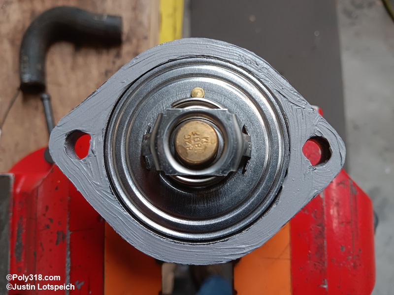
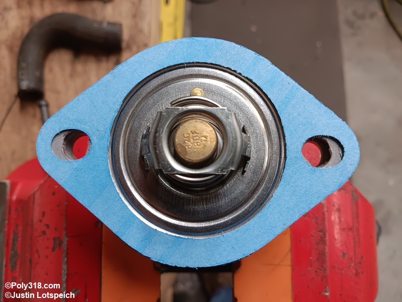
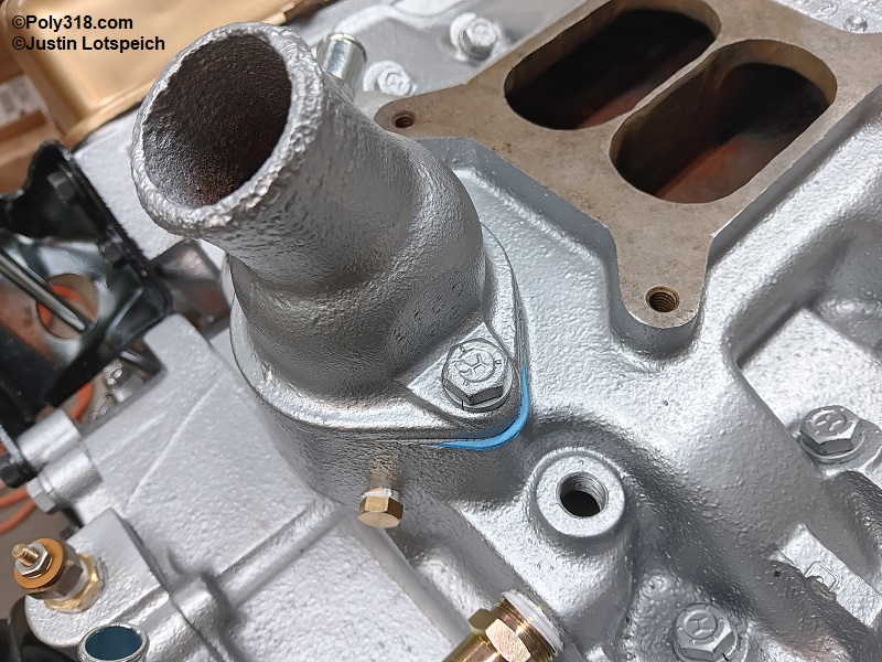
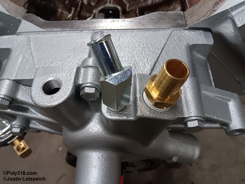
Valve Cover Installation
I glue the cork valve-cover gaskets to the covers so that they stay together when removing them from the engine for post-break-in valve spring replacement, hot valve adjustment, and routine valve adjustment. Wipe the valve cover sealing surface with lacquer thinner to clean all oil. Using the same method as the oil-pan gaskets, set the valve-cover gaskets on cardboard with the valve-cover side up, brush Permatex 80019 gasket maker onto the “up” side, and let them tack up until the liquid doesn’t transfer to a finger. Gently position the gaskets onto the covers pressing them over the alignment tangs.
Slide the cleaned cupped washers over the cleaned bolts followed by the new fiber or rubber seals. Line up the valve cover on the head and set it into place. Install the bolts and gently tighten the bolts with a 1/4″ drive ratchet in three stages until the gaskets just seat which should be no more than 15 lb.ft. Warning: Overtightening the bolts will bend the valve covers, damage the gaskets, and create leaks. Install any breathers, positive crankcase ventilation (PCV) valve, or draft tube.
Exhaust Manifold Installation
If installing the exhaust manifolds/headers before installing the engine into the vehicle/vessel, wipe off the head flanges with lacquer thinner. If using studs, slide the gaskets onto the studs, slide on the manifold/header, and start the nuts. The gaskets do not typically require sealant, although Permatex Ultra Copper 81878 may be used as a skim coat for problematic exhaust leaks. Using the sequence in Figure 35a, torque the nuts to 10, 20, and then 25 lb.ft. Do not overtighten the nuts or the cast iron manifold ears can break.
If using bolts, slide one bolt through the manifold/header on each end, slide the gasket over the protruding threads, lift the manifold/header into place, and start the two bolts but do not tighten them. Using a finger to jostle the gasket around, start the other bolts. Torque the bolts as previously described. Warning: RectorSeal T Plus 2 or a similar high-temp thread sealer should be used on the bottom bolts because they go through to coolant. The top bolts are blind and require no sealant.
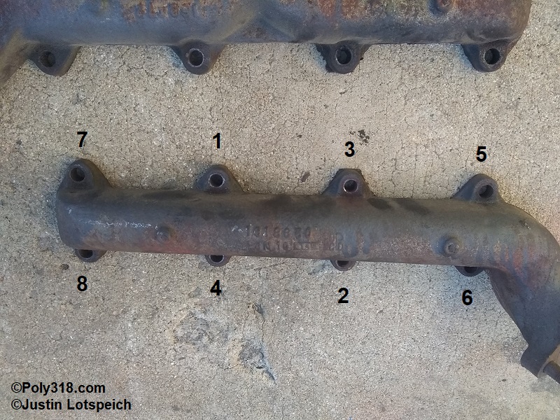
Spark Plug Adjustment and Installation
The A-block requires 3/8” short-reach spark plugs (I use Autolite 85 and typically do not need to adjust the heat). Warning: Using 3/4″ long-reach plugs will contact the piston. Lay out the new spark plugs on a clean surface.
For both points and Mopar-style electronic ignition, slide the bent end of a 0.035” spark plug wire feeler gauge in the triangle area behind the center electrode and the ground electrode. Gently pull the gauge into the gap between the electrodes feeling for some resistance as the gauge slide out of the gap (Figure 36a). If there is too much resistance or the gauge will not slide through or if there is too little or no resistance, use the feeler gauge adjustment tool to very gently and subtly pry the base of the ground electrode away from the center electrode to open the gap or toward the center electrode to close the gap (Figure 36b). Warning: Be careful not to pry against the porcelain, and make extremely slight adjustments while rechecking the gap since major or repeated adjustments can break the ground electrode.
When all the spark plug gaps are set, apply a small sab of antiseize compound to the thread to assist with future removal being extremely careful not to get compound on the electrodes or porcelain (Figure 36c). Note that this step always applies to aluminum heads, but I use antiseize on iron heads as well since it harms nothing when done properly and can help stop thread damage from carbon buildup. Slide the spark plug into the rubber of a spark-plug socket, and start the spark plug being extremely careful not to knock the ground electrode against the head where it may bend out of adjustment. Tighten the plug until the gasket hits the head, and torque it 1/4 to 1/2 turn until you feel the gasket seat. The manual specs 30 lb.ft., but I recommend going by feel.
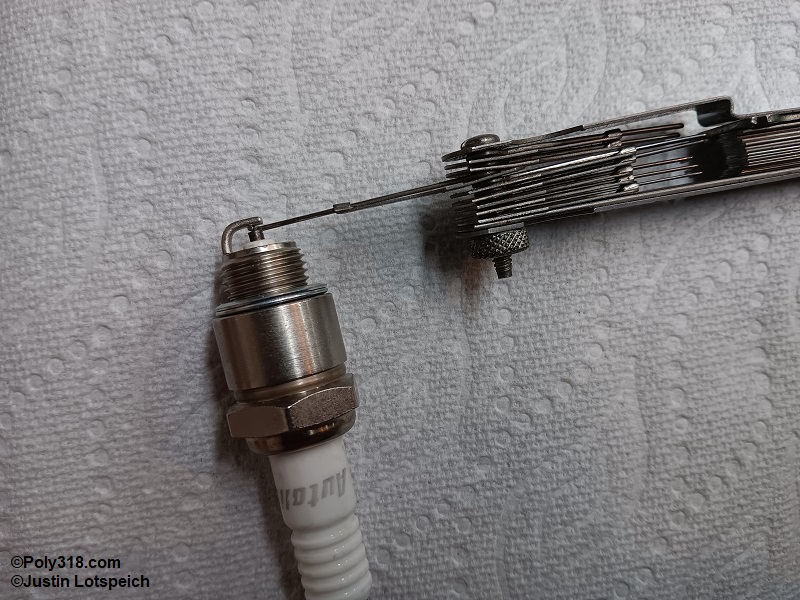
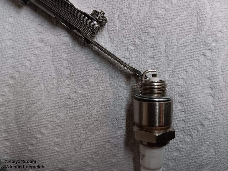
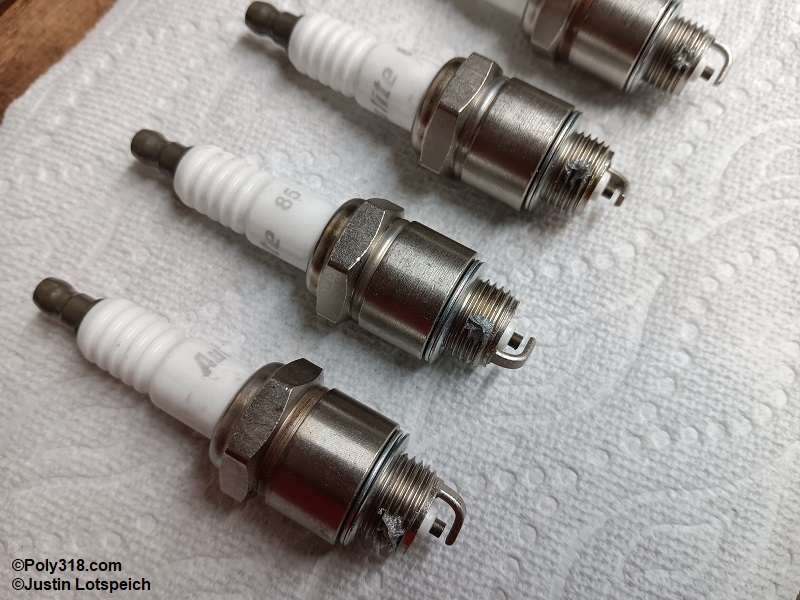
Fuel Pump Installation
Wipe off the timing cover and fuel pump or block-off plate gasket surfaces with lacquer thinner. Dress the fiber gasket on both sides with Permatex 80019 gasket maker and allow it to tack off. Place the gasket onto the pump/block-off plate, and apply assembly lube to the pump arm (Figure 37a). Apply RectorSeal T Plus 2 thread sealant to the bolt that goes through the timing cover into the crankcase. Slide the bolts through the pump, insert the pump into the timing cover, and compress the pump as necessary to start the bolts. Torque the bolts back and forth to 15 and then 30 lb.ft. (Figure 37b).
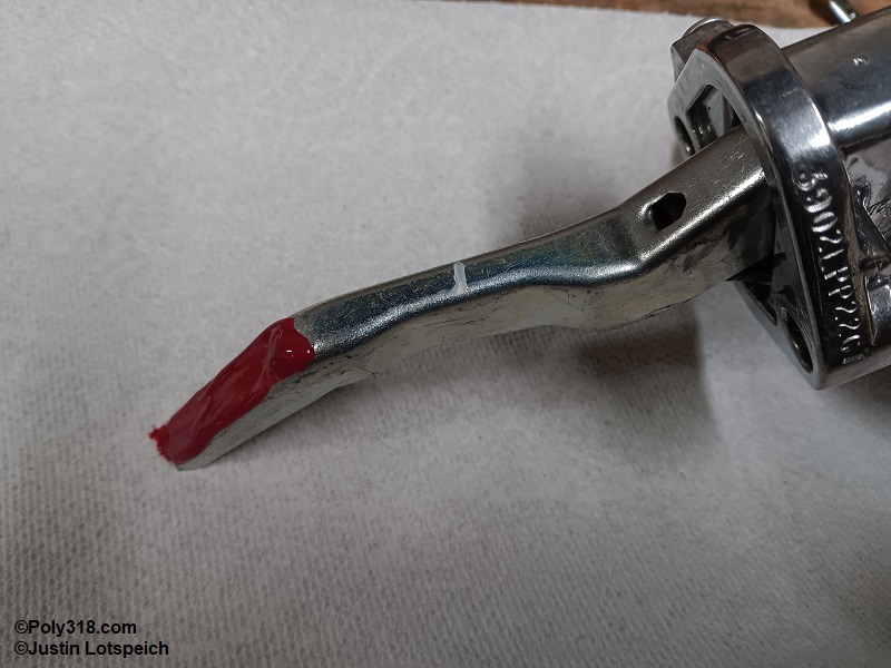
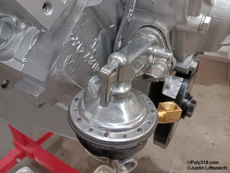
Flexplate or Flywheel Installation
Install the flexplate or flywheel onto the crankshaft hub, place Loctite red threadlocker onto the bolts, and torque the bolts to 20, 40, and then 55 lb.ft. in a star pattern (Figure 38a). Tip: Hold the crank with a breaker bar on the front bolt to stop it from rotating.
Distributor Installation and Setting Timing
While we have already set the engine timing to 30° BTDC, we need to properly check and install the distributor. For this article, I focus on a Mopar electronic distributor, but a points distributor uses the same concept for adjusting the points gap and endplay. Clean off the distributor housing and shaft, and blow off all components with compressed air to remove lint and other debris. Apply a light coat of motor oil to the housing o-ring.
Working with the housing held in a clean soft-jaw vise, rotate the shaft until one of the reluctor teeth aligns with the magnetic pickup pole (Figure 39a). Slide a nonmetallic brass 0.008” feeler gauge from the top down between the relator and pickup looking for slight drag. If adjustment is required, loosen the pickup mounting screw slightly and use a screwdriver on the base notches to move the pick-up toward or away from the reluctor until you have slight drag on all eight reluctor teeth between 0.008” and 0.012”. Note that not all teeth may have the same gap depending on machining tolerances but should fall within this tolerance. Warnings: Do not pry between the relator and pickup or bend the pickup to adjust the gap. Also, using a metallic feeler gauge will create excessive drag, so a nonmetallic gauge is necessary.
With the pickup gap set, attach a hand vacuum pump to the vacuum-advance canister. Slowly apply vacuum until you see the pickup begin to rotate. Spin the shaft while inspecting all eight reluctor teeth to ensure they clear the pickup pole. Apply 15 psi to the pump and recheck the teeth clearance, and finally apply pressure until the pick-up stops rotating and recheck the clearance. If at any point the teeth contact the pick-up, adjustment must be made to provide clearance.
Gently guide the distributor into place aligning the shaft tang with the intermediate shaft tang where the rotor points toward wherever you clocked the distributor. Ensure the distributor housing is pressed completely down.
Set up a dial indicator directly above the reluctor to measure the endplay. Press down on the reluctor and zero out the gauge with room for it to move up (Figure 39b). Insert a clean screwdriver between the reluctor and base plate, and very gently pry up until you feel resistance (Figure 39c). Note the gauge reading, which is the endplay and should fall between 0.0001” and 0.003”. Warning: Pry up on the reluctor only until feeling very slight resistance since prying too much will pull the reluctor off of the shaft. If the endplay is too tight, the slotted end of the distributor shaft must be filed down; if the endplay is too loose, the shaft needs additional shimming between the housing.
Using an oil can, place two drops of clean motor oil onto the felt pad down in the top of the shaft. Using clean hands free of oil, wipe off the rotor of all oil, and insert it over the shaft. Being methodical, place the cap on the distributor, pull the distributor out of the engine enough to rotate the shaft, and rotate the rotor and housing until the rotor points at the correct spark plug terminal with the ruluctor tooth and pickup pole aligned when the distributor is fully pressed down. For my engine, so the vacuum-advance can clears the cross-ram fuel lines and linkage, I set the #1 cylinder at approximately 4:00 when viewing the cap from the front of the vehicle (Figure 39d). Mark the housing base and engine block with a permanent marker to make alignment easy (Figure 39e), and remove the distributor until the engine is installed in the vehicle.
At this point, the engine rebuild is complete up to the camshaft break-in, and the engine can be installed where final preparation can be performed including spark-plug wires, exhaust, alternator, cooling, etc. My 390 stroker found its home in my 1956 Dodge Coronet coupe (Figures ZZZ6 and ZZZ8). I do not cover camshaft or piston ring break-in in this article, but I want to go over two post-break-in items.
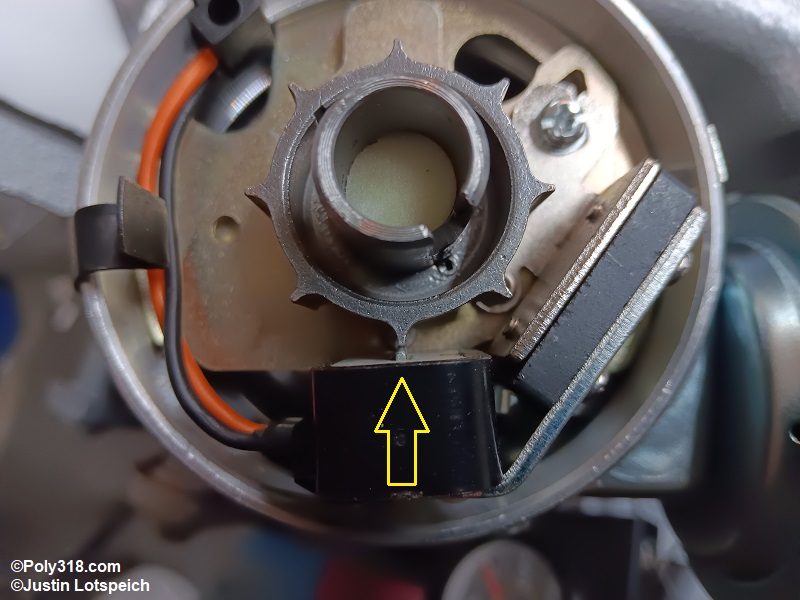
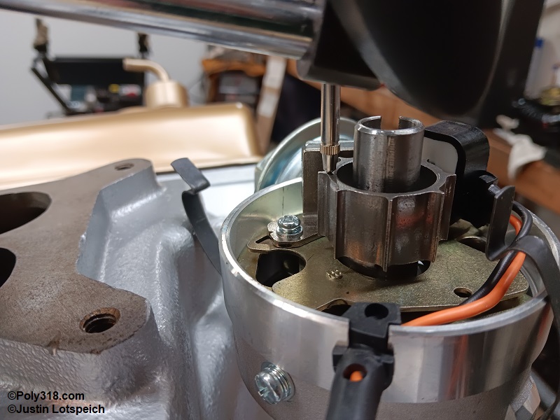
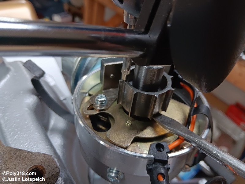
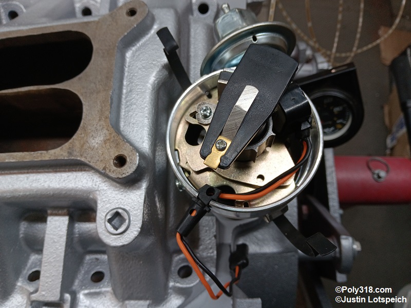
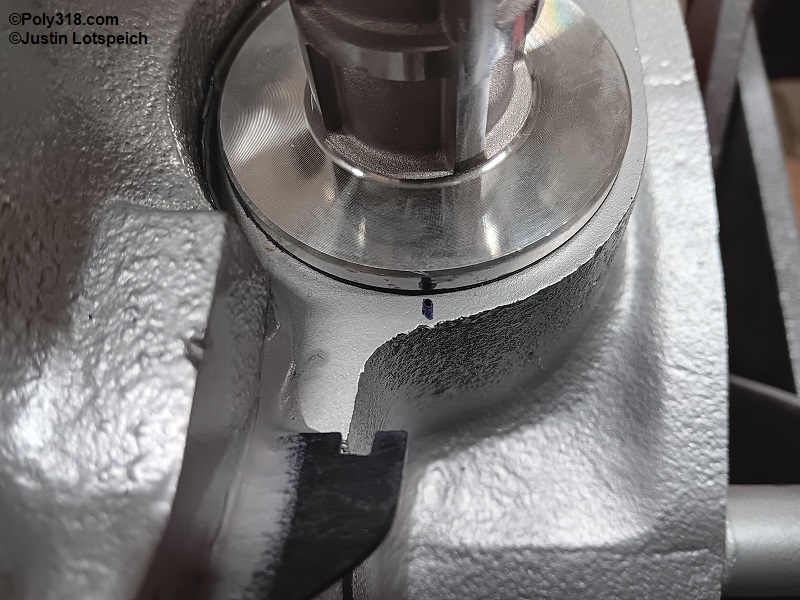
Post-break in Spring Swap
Directly after camshaft break-in while the engine is hot, remove both valve covers and all spark plugs. If you are using single valve springs, perform valve adjustment on all the valves following the process I detailed earlier only using the hot adjustment specification of 3/4 turn in for hydraulic lifters, 0.013” intake and 0.021” exhaust for mechanical lifters, or per the camshaft grinder and/or lifter manufacturer specification.
If you are using dual valve springs, you should have left the center springs out for camshaft break-in and must now install them. Rotate the crankshaft by hand until the cylinder #1 piston is at TDC on the compression stroke. Connect a compression tester hose to cylinder #1, and compress the cylinder with 100 psi of air (dial back the psi if the crankshaft tries to rotate). I rotate the piston to TDC as a fail-safe to stop the valves from dropping into the cylinder should the pressure seal break and the stem seal not catch the valve. Warning: If you drop a valve with the piston down, you will end up pulling the top end of the engine and replacing gaskets to get it out, so take your time and be methodical rather than rushing or trusting the compressed air will keep the valves from dropping.
Using an overhead valve spring compressor tool, collapse the exhaust valve until you can remove the keepers (Figure 40a). Remove the keepers, tool, and retainer, setting them on a clean surface. Drop the clean center spring over the stem seal making sure it seats fully, and reinstall the retainer and keepers. After removing the compressor tool, use a clean rubber mallet to smack the edge of the retainer to ensure the keepers are seated, being prepared for a loud pop of compressed air as the valve pops open. (Figure 40b). Move onto the intake valve for cylinder #1, and then follow the firing order 18436572 turning the crankshaft for TDC compression stroke for each cylinder before removing the springs.
When all the center valve springs have been installed, follow the procedure I describe above for adjusting the valves, only use the hot specification. Install the valve covers, spark plugs, and spark-plug wires. Note: If installing the second springs took long enough where the engine has cooled considerably, you will need to set the valves using the hot spec, fire the engine again until it is at running temperature, and then pull the valve covers to check/adjust the valves at the hot spec. Hydraulic lifters will usually be able to take up any difference between a warm and hot engine, but mechanical lifters are far more dependent on proper lash adjustment to where skipping this step because it is a pain may result in damage through prolonged use. Spending the additional time is well worth it considering all the time and money you already put into the engine that might be thrown away from improper valve adjustment.
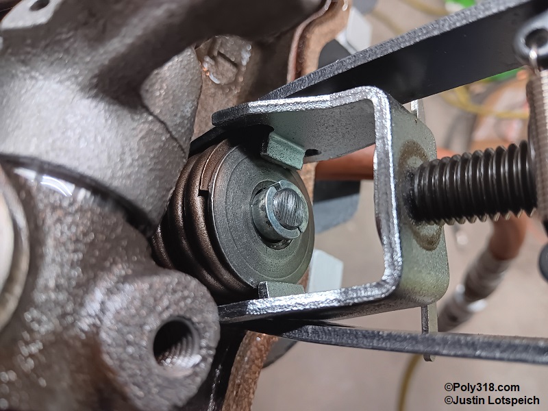
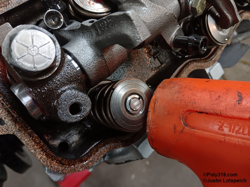
Conclusion
While an involved process that requires many steps and care, engine rebuilding can be accomplished by many mechanics of differing levels of experience. I have covered the methods I use to rebuild an A-block engine, but I do not mean to suggest that what I have detailed is the only correct way to perform the task. Figure 41a shows the finished engine, and Figure 41b shows it after I installed it in the 1956 Dodge Coronet coupe. In Figure 41c, you can see the engine ready for camshaft break-in, including my test water temperature, oil pressure, and air-fuel ratio gauges positioned where I can easily monitor the engine vitals from the engine compartment.
I hope this article along with the disassembly article provide useful information for those interested in rebuilding an engine or performing different engine work covered in them.
