Poly 318 Oil Bypass Valve &
Spin-on Filter Adapters
(applicable to 277, 301, 303, 313, 326 A-blocks and some content applicable to Gen I Hemi and Hemi-block Poly Engines)
Poly A-block, Hemi, and Hemi-block Poly Oil Bypass Valve
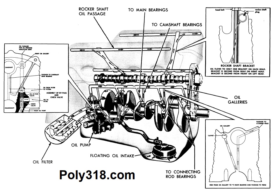
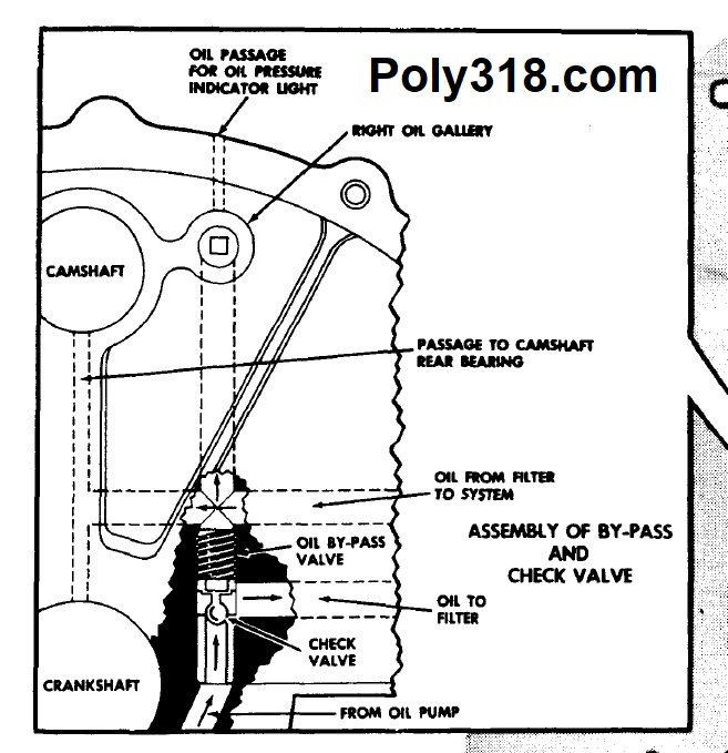
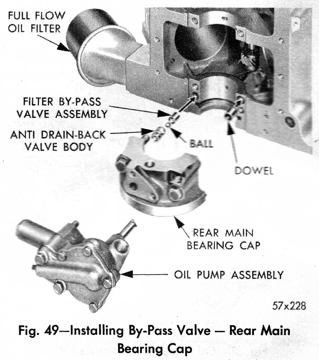
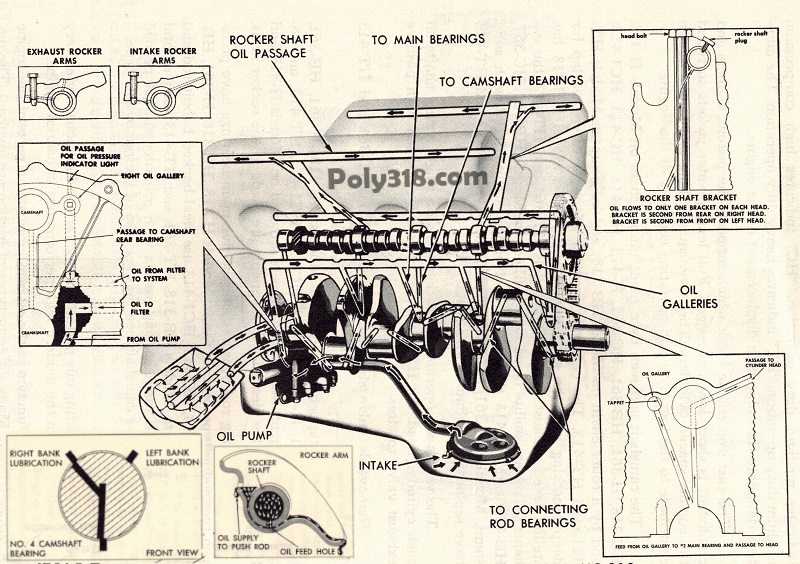
All A-blocks have an oil hole drilled through the block underneath the #5 (rear) main cap on the right side. In many early A-blocks from 1956 – 1961 with reports of some 1962 blocks, the factory installed a bypass valve in the block (Figures 1 – 6), similar to Gen I Hemi (e.g. 331, 354, 392) and Hemi-block poly (e.g. 270, 315) engines. The one-way valve includes a steel housing with an internal spring and ball valve. The purpose of the valve was to open and recirculate unfiltered oil in the event the canister oil filter clogged and oil pressure grew too high. Mopar realized three issues with the design by the early 60s:
- If the oil filter element clogged, there were major issues with either lack of oil maintenance or fragmenting parts that would likely destroy engine components regardless of bypassing the filter.
- The new spin-on filter design had a higher bypass pressure rating than the block’s bypass valve, so the block bypass would trip before the spin-on filter causing unfiltered oil to circulate through the engine even though the spin-on filter element was not clogged.
- The block bypass valves could corrode and come apart, sending debris through the oiling system while also bypassing the filter permanently. Once the spring or ball valve came apart, the oil filter would be permanently bypassed.
To address the issues, Mopar began plugging the passage with a cast plug in blocks already drilled and eventually stopped drilling the passage completely through to where no plug was needed. Unfortunately for many 1956 – 1961 A-block owners, many have their oil filters bypassed due to the corroded valve. For example, the last 1957 – 1961 poly 318 engines I tore down that had the bypass valve installed were missing the spring and ball where the filter was completely bypassed. 1956 – 1962 engines running both earlier cartridge and later spin-on filters should always have the internal bypass valve inspected and if present removed and the passage plugged.
Removal and Plugging the A-block Valve
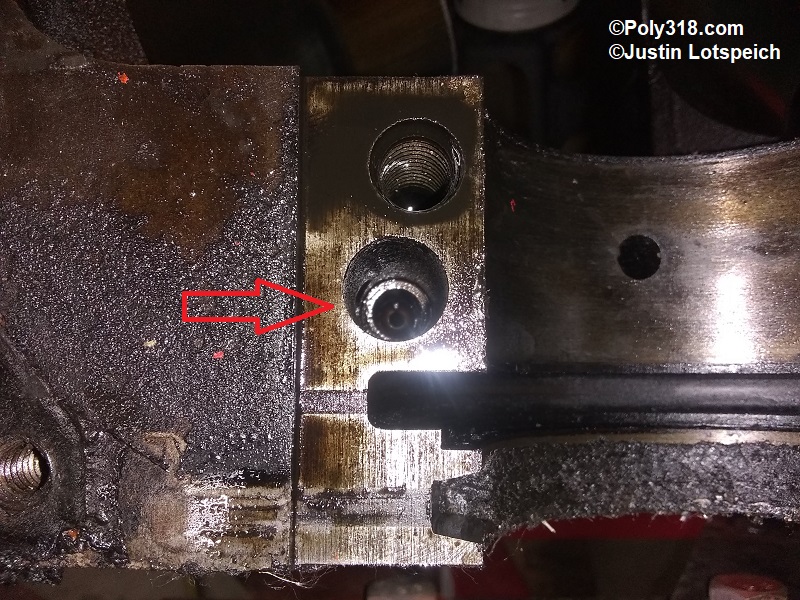
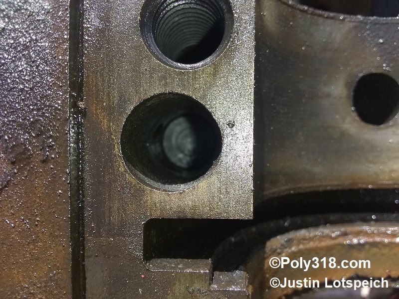
Ideally, the bypass valve should be removed and plugged with the engine disassembled during a rebuild or overhaul so that all the oil galleries can be washed out with a brush and blown out well with compressed air to remove all metal shavings. However, the removal and plugging can happen with the engine in the vehicle, but there is a risk that shavings will remain downstream the filter and could be flushed into the system and damage components. To confirm if the engine has and to remove the bypass valve, you must drop the oil pan, remove the oil pump, and remove the rear main cap. After confirming the engine has an oil bypass valve or the remaining housing still in place, remove the oil pressure gauge hose, sending unit, or pipe plug from the top of the engine near the distributor, insert a length of 1/4″ hardened steel rod as a drift, and hammer out the bypass valve housing. I have encountered some valve housings that refuse to be driven out even with torch heat, and they require drilling out from the bottom moving incrementally up in bit size. If doing so with the crank installed, an extra-long drill bit will keep the drill motor away from the crankshaft journal. Wrap the crank journal extremely well to protect it from the drill/bit. Once the valve housing is drilled out, pull the plug in the oil filter well and blow compressed air through it to flush out any shavings from that gallery since it is downstream the filter to where any shavings will circulate through the engine. Blow air down from the gauge/sending unit port near the distributor. Blow air through the filter intake gallery that is off to the side in the filter well. Finally, run a magnet up from the main cap to pick up any remaining shavings.
I know of two methods to plug the passage:
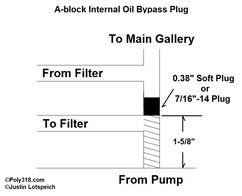
Soft Plug: The bore is typically 0.38″ diameter but should be confirmed before sourcing a soft plug. Use a deep-cup plug since dish and shallow-cup plugs will try to flip on their axis in the hole. Spray out the gallery with brake cleaner and remove all oil until the gallery wall is clean. Apply a liberal coat of red Loctite on a cotton swag to the gallery walls where the plug will seat. Using a drift or long bolt, drive the plug into the block square until there is 1-5/8″ – 1-3/4″ distance between the plug and the main cap pad. Check that the plug is driven in above the filter intake passage so oil can flow unabated from the pump to the filter (Figure 7). Do not drive the plug in too deep because it can block the filter outlet passage located above it.
Threaded Plug (Figure 7): The oil passage is 0.38” diameter, slightly larger than the .036” used for 7/16” threads. Tap the passage 7/16”-14 and plug it with a 7/16”-14 black-oxide Allen-head plug using red Loctite and torquing it to 35 ft.lbs. against the lip where the threads stop. Make sure to tap far enough above the filter intake passage to where when the plug is in place, oil can still flow unabated from the pump to the filter. The issue with this method is that the tap and/or extension must be long enough to reach far enough into the bore, and tapping hard cast iron can be difficult. I’d opt for the soft plug method but wanted to provide this alternative.
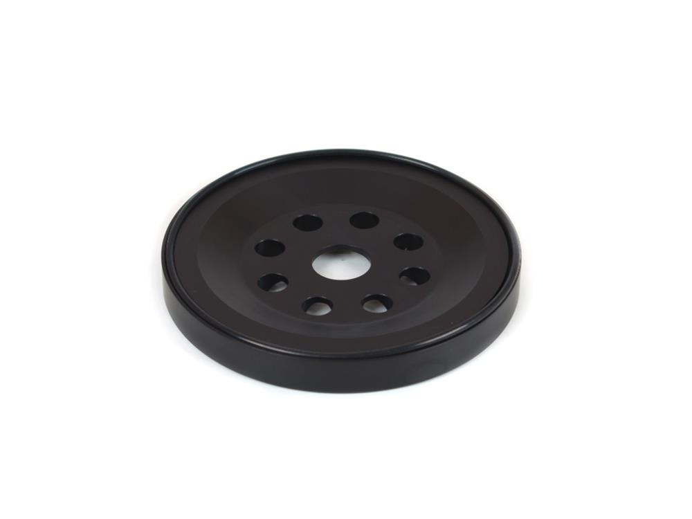
Aftermarket bypass plug (Figure 8): The only available bypass plugs carried by Speedway Motors (910-11048), Donovan (2600-0190), and Hot Heads Research (20120) are made for Gen I Hemis and Hemi-block polys and are too large (0.552” x 1.650”) for A-blocks. No similar plug exists for the A-block.
Figures

Spin-on Filter Adapters
LA 273, 318, 340, 360 spin-on filter hardware, including aftermarket adapters, can be fitted onto A-blocks with cartridge filters. If running a spin-on filter, it is important to plug the block bypass described above (if applicable) since it has a lower activation psi than the spin-on bypass and can lead to unfiltered oil circulating throughout the engine.
For Factory Flow Rates:
Use a factory style LA oil-filter adapter and stud with a Felpro 70522 fiber gasket to seal to the block. Do not use rubber gaskets since they are prone to squeezing out and leaking. Tacking the gasket in place with a few dabs of grease helps during installation. Tighten the bolt to 25 ft.lbs.
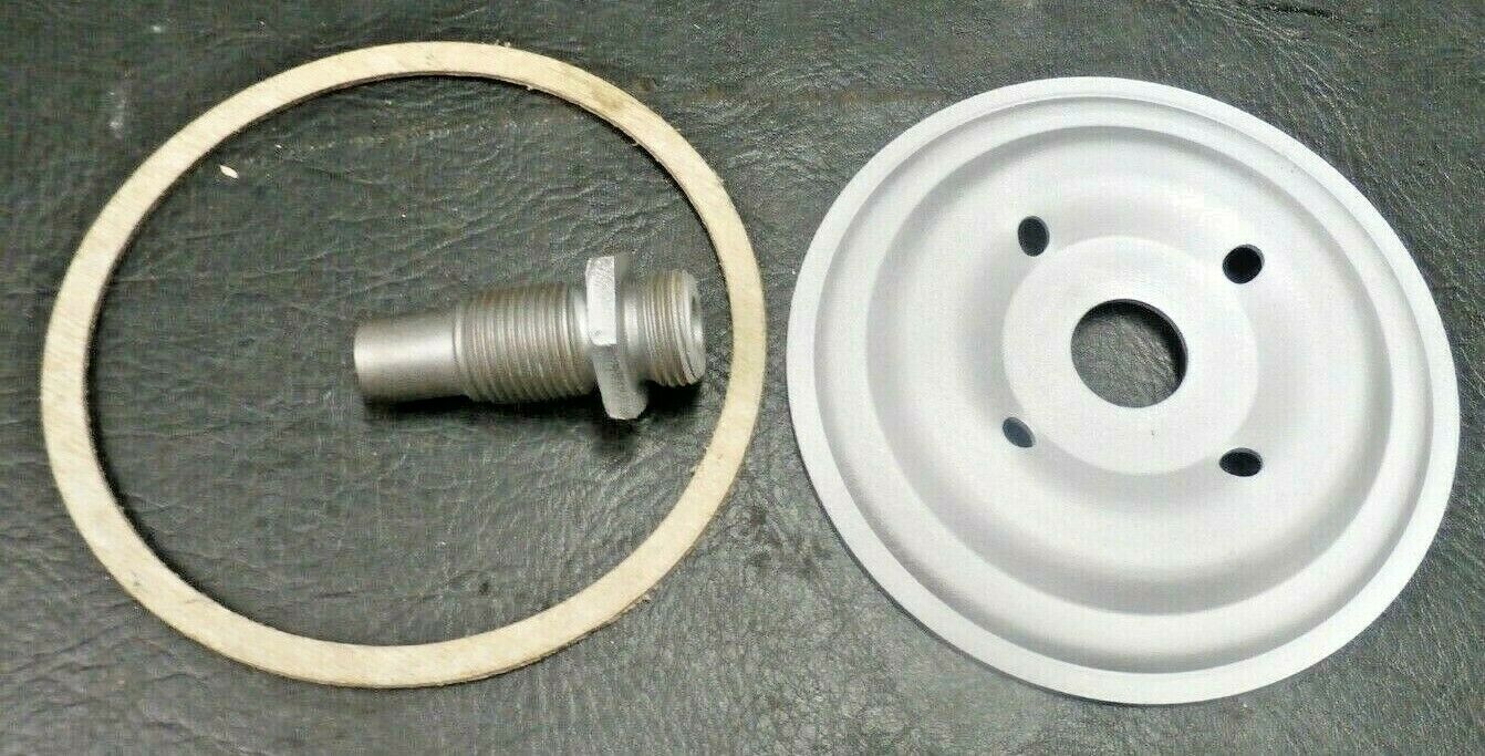
For High-flow Rates:
Use the factory style adapter plate but drill additional holes for greater volume. See my technical article on other performance oil system modifications.
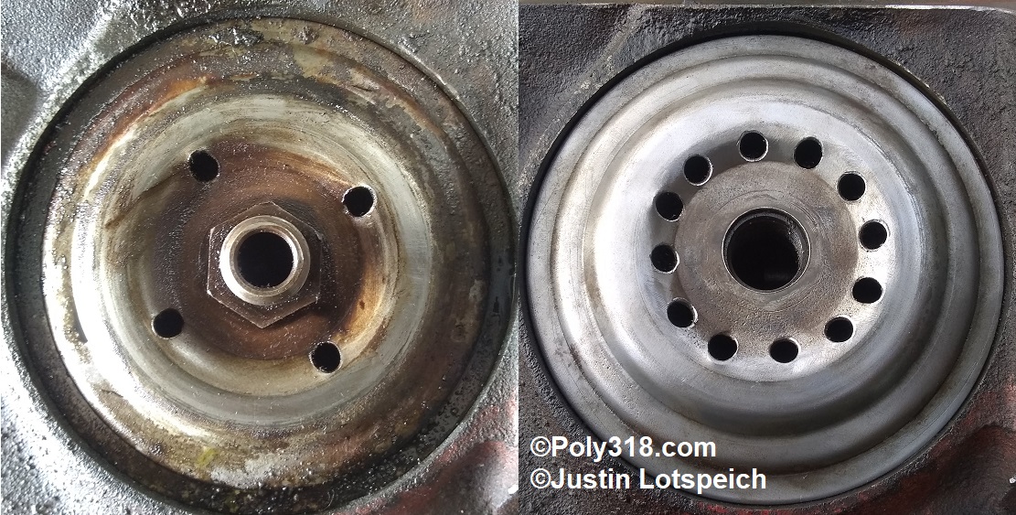
Another option is to use Crown Automotive stud CWA-53007563AB and a Canton 22-575 adapter. Along with higher flow, this adapter utilizes an o-ring against the block that negates the need for the fiber gasket.
